Table of Contents
Advertisement
Quick Links
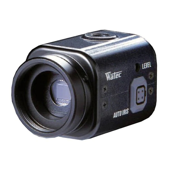
WAT-902B
CCD CAMERA
OPERATION MANUAL
INTRODUCTION:
Thank you for choosing the WAT-902B, B/W CCD Camera.
WATEC hopes that both the quality and design satisfy your requirements.
Before proceeding to install or operate the WAT-902B, please read and understand thoroughly the contents of this
Operation Manual.
For future reference we also advise safe keeping of this manual.
CAUTIONS:
1. Use only the AD-901 or equivalent power adaptor for the WAT-902B. Power supplied without voltage stabilization
and/or the voltage range is not maintained at ±10% 12VD. C. may cause damage to the WAT-902B.
2. Do not expose the WAT-902B to wetness or high moisture conditions. The WAT-902B is designed and approved
for indoor use only.
If the location of the WAT-902B is outdoors or in an outdoor like environment, we recommend that you use an
OUTDOOR CAMERA HOUSING.
3. Avoid the striking of hard objects or dropping the unit.
4. Do not disassemble and/or modify the WAT-902B or the component parts or accessories. WATEC can not be held
responsible for equipment failure or any damage or trouble caused by such action.
5. Do not install the WAT-902B near a heat source, such as radiators or heating air ducts, or in a position subject to
direct sunlight ※, excessive dust, mechanical vibration or shock.
6. When the WAT-902B is used under fluorescent or mercury lighting conditions, a flickering phenomemon may
occur on the monitor screen. This does not mean that the WAT-902B is damaged.
7. When installing the WAT-902B in an industrial or commercial environment (i. e. within equipment housing, near
other electronic device, etc.) make sure to avoid any strong electromagnetic field. Otherwise the video output may
be distorted and monitor sharpness compromised.
8. Check and protect the WAT-902B from any source generating a strong electromagnetic field from your equipment,
when the WAT-902B is fitted near or inside the unit.
9. Do not connect any power supply directly to the VIDEO OUT terminal of the unit. This may cause damage.
10. When a cable operation system such as video/power multiplex transmission is being used, check the specifications
or requirements of your monitor for proper connection to the video signal terminal of the WAT-902B.
11. Do not make connections and/or operate the WAT-902B with wet hands.
12. Should the WAT-902B not work properly, switch off the power and then check that power and video terminals are
properly connected.
※ Sunlight shinning directly onto the camera lens can cause damage to the CCD.
CONTENTS:
Using the contents figures below, check to make sure all parts are present before use.
The WAT-902B parts (complete unit)
Lens cap
WAT-902B
D.C. plug
DESCRIPTION OF CAMERA PARTS (Unit:mm)
(Front)
①CCD front face ②Lens mount(CS mount type) ③Hexagonal focusing adjustment screws(3pcs)
④Tripod mounting screw holes(Upper and lower) ⑤AUTO IRIS ⑥VIDEO OUT ⑦SHUTTER switch
⑧POWER
Remove the four screws from
the upper housing cover.
①CCD front face (light receiving face of the CCD camera)
NOTE: 1. Handle the CCD and lens with special care.
2. Always attach the lens cap so as to protect the lens and the CCD from contamination and damage.
3. Dirt, water or oil deposits on either will cause an unclear picture on the monitor and scratches will
become permanent damage.
②Lens mount (CS mount type)
NOTE: Any standard model C mount lens can be attached to the WAT-902B, if our optional C mount ring,
30CMA-R is fitted to the unit.
③Hexagonal focusing adjustment screws (for fine focusing adjustment by the lens mount ring.)
There are three hexagonal focusing adjustment screws each placed at intervals of 120°around the lens mount
ring for the forward and backward motion of the lens mount.
④Tripod mounting screw holes (Upper and lower)
Thread size and depth are the same as those for the standard camera tripods.(U1/4" )
⑤AUTO IRIS
Female connector for the auto-iris lens.
NOTE: When the BLC(back light compensation)switch is ON in conjunction with the auto iris lens, the iris
control is shown within the restricted area on the monitor screen. See Sec. 9 of OPERATION in the
operation manual for a more detailed explanation.
Iris connector
⑥VIDEO OUT-The RCA terminal for video signal output.
NOTE: A 3C2V or 5C2V cable with 75Ω impedance must be used for connection with the WAT-902B.
⑦SHUTTER switch-The electronic shutter speed conversion switch
⑧POWER-The power input terminal
⑨BACK LIGHT OFF/ON-The switch for the Back Light compensation function.
(Side)
(Rear)
⑩AGC OFF/ON-The AGC (Auto gain control) operation switch
⑪AGC Lo/Hi-AGC gain switch
⑫Γ OFF/ON-The gamma ON/OFF selection switch
Pull the upper housing cover
upwards.
OPERETION:
NOTE: Ensure that before any connections are made to the WAT-902B the power is switched OFF.
1) Remove the Lens Cap from ① the CCD front face and attach the lens.
2) Using the Auto Iris lens
3) Insert the DC plug of the power adaptor to POWER⑧ on the rear pannel of the WAT-902B.
Any shutter speed can manually be selected at your request.
The electronic shutter function is set to ON upon shipment.
Symbol Shutter mode selection chart
ON
EIA: 1/60~1/100000
CCIR: 1/50~1/100000
OFF
EIA: 1/60
CCIR: 1/50
FL
EIA: 1/100
CCIR: 1/120
NOTE: When the SHUTTER switch is ON, the shutter function is automatically converted to the electronic iris
mode and the shutter speed is determined in combination with the brightness of an object and the iris of
the lens in the range shown on the chart on the left.
NOTE: The optional power adaptor AD-901 (DC+12V, 250mA) is recommended for use with the WAT-902B.
NOTE: The switch is set to OFF(upwards) upon shipment.
NOTE: When the switch is set upwards, AGC is ON and when it is set downwards, AGC is OFF.
The switch is set to ON upon shipment.
The switch is set to Hi gain at the upper position and to Lo gain at the lower position.
The switch is set to Lo upon shipment.
The switch is ON at the upper position and OFF at the lower position.
The switch is set to ON (upper) upon shipment.
NOTE: When the C mount type lens is used, mount the optional 30CMA-R, C mount conversion ring before the
lens is mounted.
: Confirm the specifications of the lens to be used, when it can not be mounted onto the WAT-902B smoothly.
(Mounting a nonstandardized lens may cause damage to the threads of the lens and lens mount too.)
Connect the iris control cable to AUTO IRIS⑤ on the WAT-902B, when the auto iris lens is used.
IMPORTANT NOTES FOR AUTO IRIS USAGE
: Ensure that the connector mentioned in the operation manual of the Auto-Iris lens
can be applied to the one shown in the diagram on the right and connect it firmly to
the connector on the right side of the WAT-902B.
: Insert the pins as shown in the picture on the right. If the pin configuration is
different from that shown, use the special adaptor supplied with this unit.
CAUTION: Do not touch the power pin or the signal control pin with the Common
(GND) pins on the extra connector for the Auto Iris lens.
NOTE: Ensure that the power adaptor is not ON before insertion of the DC plug into POWER⑧.
IMPORTANT NOTES FOR POWER ADAPTOR USAGE
: Use a stabilized power adaptor designed for DC+12V±10% with a current
capacity of 250mA.
: Use the optional DC plug when the shape or polarity of the DC plug of the DC
power adaptor can not be fitted to POWER⑧ on the WAT-902B.
: Connect the cables to the DC adaptor using the drawing on the right.
Caution : Be careful not to touch any other terminal while wiring.
NOTE : This may cause damage to the WAT-902B and power adaptor or may cause
fire if the above care and attention are not adhered to.
Common (GND)
Signal Control
Common (GND)
Power
Configuration of the Auto Iris lens connector
(on the side of the WAT-902B)
DC+12V
COMMON (GND)
Advertisement
Table of Contents

Related Manuals for Watec WAT-902B


Summary of Contents for Watec WAT-902B
- Page 1 The switch is set to Lo upon shipment. 5. Do not install the WAT-902B near a heat source, such as radiators or heating air ducts, or in a position subject to ⑫Γ OFF/ON-The gamma ON/OFF selection switch Remove the four screws from direct sunlight ※, excessive dust, mechanical vibration or shock.
- Page 2 NOTE: In cases when the unit can not be focused manually, use the focusing adjustment method set out below. control. Shutter 1/60 sec. 1/50 sec. : Select the AGC ON-Hi position to enlarge the AGC range by two iris stops when the WAT-902B is used in IMPORTANT NOTES ON FOCUSING 1/100 sec. 1/120 sec. a dark environment.
Need help?
Do you have a question about the WAT-902B and is the answer not in the manual?
Questions and answers