Advertisement
Table of Contents
- 1 Table of Contents
- 2 Specifications
- 3 Service Data
- 4 Ecm Main Relay
- 5 Exhaust Manifold Temperature Sensor and Cylinder Temperature Sensor
- 6 Cylinder Block
- 7 Buzzer
- 8 Neutral Switch Bracket
- 9 Under Oil Seal Housing
- 10 Forward Gear Thrust Washer
- 11 Exhaust Cam Shaft
- 12 Wiring Diagrams
- 13 Wire Routing
- Download this manual
See also:
Service Manual
Advertisement
Table of Contents

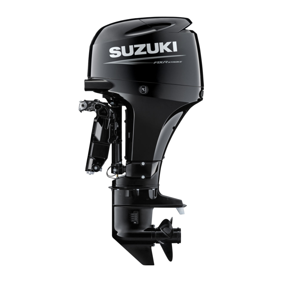
Summary of Contents for Suzuki DF 40
- Page 1 For '03 model SUPPLEMENTARY SERVICE MANUAL 9 9 5 0 1 - 8 7 J 2 0 - 0 1 E...
-
Page 2: Table Of Contents
DF40/50 “K3” (2003) MODEL FOREWORD This supplementary service manual describes the outline, technical data and servicing procedures for the “K3” (2003) models outboard motor. Please read and thoroughly familiarize yourself with this information before using it for your service activities. NOTE: Use this supplement with the following service manual: DF40/50 Service Manual ( P/no, 99500-87J0 •... -
Page 3: Specifications
2 DF40/DF50 “K3” (‘03) model GENERAL INFORMATION SPECIFICATIONS Data Item Unit DF40T DF40QH DF50T/50WT DF50WQH PRE-FIX 04001F 05001F DIMENSIONS & WEIGHT Overall length (front to back) mm (in) 756 (29.8) 852 (33.5) 756 (29.8) 852 (33.5) Overall width (side to side) mm (in) 382 (15.0) 382 (15.0) - Page 4 Engine oil amounts 2.2 (2.3/1.9) : Oil change only L (US/Imp. qt) 2.4 (2.5/2.1) : Oil filter change Gear oil SUZUKI Outboard Motor Gear Oil (SAE #90 hypoid gear oil) Gearcase oil capacity ml (US/Imp. oz) 610 (20.6/21.5) BRACKET Manual trim and gas...
-
Page 5: Service Data
4 DF40/DF50 “K3” (‘03) model SERVICE DATA Data Item Unit DF40T/40QH DF50T/50WT/50WQH POWERHEAD Recommended operating range r/min 5200 – 5800 5900 – 6500 Idle speed r/min 850 ± 50 (in-gear: approx.850) *Cylinder compression kPa (kg/cm , psi) 1300 – 1600 (13 – 16, 185 – 228) *Cylinder compression max. - Page 6 DF40/DF50 “K3” (‘03) model 5 Data Item Unit DF40T/40QH DF50T/50WT/50WQH VALVE / VALVE GUIDE mm (in) 24.6 (0.97) Valve diameter mm (in) 21.5 (0.85) Tappet clearance 0.18 – 0.24 (0.007 – 0.009) mm (in) (Cold engine 0.18 – 0.24 (0.007 – 0.009) mm (in) condition) Valve seat...
- Page 7 6 DF40/DF50 “K3” (‘03) model Data Item Unit DF40T/40QH DF50T/50WT/50WQH CYLINDER/PISTON/PISTON RING Limit mm (in) 0.060 (0.0024) Cylinder distortion mm (in) 0.020 – 0.040 (0.0008 – 0.0016) Piston to cylinder clearance Limit mm (in) 0.100 (0.0039) mm (in) 71.000 – 71.020 (2.7953 – 2.7961) Cylinder bore mm (in) 50 (2.0) from cylinder top surface...
- Page 8 DF40/DF50 “K3” (‘03) model 7 Data Item Unit DF40T/40QH DF50T/50WT/50WQH CRANKSHAFT / CONROD Conrod small end mm (in) 18.003 – 18.011 (0.7088 – 0.7091) inside diameter mm (in) 0.020 – 0.040 (0.0008 – 0.0016) Conrod big end oil clearance Limit mm (in) 0.065 (0.0026) Conrod big end...
- Page 9 8 DF40/DF50 “K3” (‘03) model Data Item Unit DF40T/40QH DF50T/50WT/50WQH ELECTRICAL Degrees at r/min Ignition timing ATDC 1° – BTDC 27° ATDC 1° – BTDC 24° r/min 6500 7000 Over revolution limiter Ω 168 – 252 CKP sensor resistance at 20°C Ω...
-
Page 10: Ecm Main Relay
DF40/DF50 “K3” (‘03) model 9 ECM MAIN RELAY ! 09930-99320 : Digital tester " Tester range : # # (Continuity) (1) Disconnect ECM main relay from wire. (2) Check continuity between terminal 1 and 2 each time 12 V " is applied. -
Page 11: Cylinder Block
10 DF40/DF50 “K3” (‘03) model CYLINDER BLOCK Cylinder block has been changed because of the change of tem- perature sensor. Hole for exhaust temperature sensor Hole for cylinder temperature sensor Ê 2002: Ê Ê 2003: 2002: Ê 2003: BUZZER Buzzer in the remote control box (side-mount-type) has been changed in function and shape. -
Page 12: Neutral Switch Bracket
DF40/DF50 “K3” (‘03) model 11 NEUTRAL SWITCH BRACKET The neutral switch bracket has been changed to be secured with two bolt from the middle of 2002 year model. NOTE: When install a late type neutral switch bracket to the early cylin- der, secure the neutral switch bracket with one bolt. -
Page 13: Exhaust Cam Shaft
12 DF40/DF50 “K3” (‘03) model EXHAUST CAM SHAFT The shape of exhaust cam shaft and exhaust cam sprocket have been changed from the middle of 2002 year model. Arrow mark Arrow mark Early Exhaust cam sprocket Late Early Late... -
Page 14: Wiring Diagrams
DF40/DF50 “K3” (‘03) model 13 WIRING DIAGRAMS... -
Page 15: Wire Routing
14 DF40/DF50 “K3” (‘03) model WIRE ROUTING... - Page 16 DF40/DF50 “K3” (‘03) model 15...
- Page 17 16 DF40/DF50 “K3” (‘03) model...
- Page 18 DF40/DF50 “K3” (‘03) model 17 Starter motor Tighten bolt with PTT relay ground wire, battery cable ground wire and harness CTP switch ground wire. Starter motor sub cable Grommet IAT sensor IAC valve Engine wiring harness Battery cable Route engine wiring harness on battery cable Battery cable Route battery cable on fuel hose.
- Page 19 Prepared by Marine & Power Products Division July, 2002 Manual No. 99501-87J20-01E Printed in Japan...
- Page 20 Printed in Japan...


Need help?
Do you have a question about the DF 40 and is the answer not in the manual?
Questions and answers