
Related Manuals for Suzuki DF4A


Summary of Contents for Suzuki DF4A
- Page 1 DF4A DF5A DF6A OWNER’S MANUAL ENGLISH https://www.boat-manuals.com/...
- Page 2 • Do not hold onto the motor cover or any This symbol appears in various locations on other parts of your outboard motor while your Suzuki product to refer you to important getting on or off your boat. information in the owner’s manual.
- Page 3 FOREWORD • Never remove the flywheel cover (except for when emergency starting). Thank you for choosing a Suzuki outboard motor. Please read this manual carefully and NOTE: review it from time to time. It contains important Mounting radio transceiver or navigational...
-
Page 4: Table Of Contents
TABLE OF CONTENTS IDENTIFICATION NUMBER LOCATION..........5 FUEL AND OIL........5 LOCATION OF SAFETY LABELS ..8 LOCATION OF PARTS....... 10 MOTOR MOUNTING......11 PROPELLER SELECTION AND INSTALLATION........12 ADJUSTMENT........13 OVER-REVOLUTION LIMITING SYSTEM..........15 OPERATION OF TILTING SYSTEMS..........16 INSPECTION BEFORE BOATING ... -
Page 5: Identification Number Location
Fuel system damage or outboard motor performance problems resulting from the use of such fuels are not the responsibility of Suzuki and may not be covered under the New Outboard Motor Limited Warranty. FUEL AND OIL Fuel containing 5% or less methanol may be suitable for use in your outboard motor if they contain cosolvents and corrosion inhibitors. - Page 6 Always select ple and pets. good quality engine oil. Suzuki recommends the use of SAE 10W-40 or Always take the following precautions when 10W-30 SUZUKI MARINE 4-CYCLE ENGINE refueling: OIL.
- Page 7 GEAR OIL Suzuki recommends the use of SUZUKI OUT- BOARD MOTOR GEAR OIL. If it is not avail- able, use SAE 90 hypoid gear oil which is rated GL-5 under the API classification system. https://www.boat-manuals.com/...
-
Page 8: Location Of Safety Labels
LOCATION OF SAFETY LABELS Read and follow all of the labels on your out- Keep the labels on your outboard motor or fuel board motor or fuel tank. Make sure you under- tank. Do not remove them for any reason. stand all of the labels. - Page 9 WARNING AVERTISSEMENT Secure both mounting bolts and clamps to avoid motor drop. See owner’s manual. Fixer les deux boulons de montage et des brides pour éviter la chute du moteur. Voir le manuel du propriétaire. Label symbol meanings These symbols mean as follows; : General warning symbol : Engine start (Caution or Warning)
-
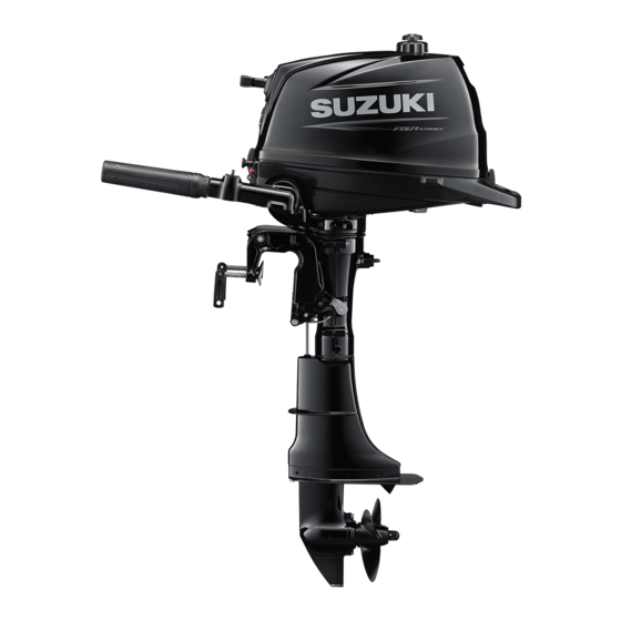
Page 10: Location Of Parts
LOCATION OF PARTS Air-vent screw Motor cover Starter grip Built-in Shift lever fuel tank Throttle tension adjuster Rear handle Tilt up lock arm Throttle control grip Fuel cock lever Steering tension Clamp screw adjuster Pilot water hole Tilt pin Flush plug Clamp bracket Anode Anti-cavitation... -
Page 11: Motor Mounting
“Certification Plate”. Contact your authorized Suzuki marine dealer if you are unable to locate the hull “Certificate Plate”. Install 8 mm bolts, washers, lock washers and nuts, as illustrated and tighten the bolts sequen- Proper transom height is important for good tially. -
Page 12: Propeller Selection And Installation
Occasionally check the clamp screws for tightness. Ask your authorized Suzuki marine dealer to assist you in selecting a suitable propeller for your boat. You can determine if your propeller is appropri-... -
Page 13: Adjustment
• Trim angle too large (Boat tends to “porpoise”) 1. Coat the propeller shaft splines 1 liberally with Suzuki water resistant grease to help prevent corrosion. 2. Place the stopper 2 on the shaft. • Proper trim angle 3. - Page 14 STEERING TENSION ADJUSTMENT Make a test run in the boat to determine if the The steering on your outboard motor should be trim angle needs to be adjusted. smooth and not tight. Adjust the steering ten- To adjust the trim angle: sion so that there is only a slight resistance to 1.
-
Page 15: Over-Revolution Limiting System
Over-Revolution Limiting System. NOTE: If idle speed cannot be set within the specified Consult your authorized Suzuki marine dealer range, contact your authorized Suzuki Marine if the Over-Revolution Limiting System acti- Dealer. vates for no apparent reason. -
Page 16: Operation Of Tilting Systems
TILT UP LOCK ARM OPERATION OF TILTING The tilt up lock arm is used to hold the motor in SYSTEMS the fully tilted up position and shallow water position. TILT LOCK When move shift motor into FULL TILT UP POSITION “REVERSE”... - Page 17 Using separate fuel tank: NOTICE Disconnect the fuel line from the separate fuel tank. If you use the throttle grip handle to raise or Install the fuel connector cap 1 to fuel connec- lower the motor, the handle may break. tor.
- Page 18 SHALLOW WATER POSITION WARNING To set the motor in the shallow water position: 1. Shift into “NEUTRAL”. 2. Slowly tilt the motor up until you hear it make When the shallow water position is used, the a “click” sound. tilt lock will not work.
-
Page 19: Inspection Before Boating
INSPECTION BEFORE • Check the level of engine oil in the sump. BOATING NOTICE WARNING Running the engine with an insufficient amount of oil can cause serious engine dam- Failure to inspect your boat and motor before age. beginning a trip can be hazardous. Always check the oil level before each trip and Before boating, always perform the inspec- add oil if necessary. - Page 20 NOTE: NOTICE By Window A, the volume of engine oil cannot be confirmed. Running the engine with an excessive amount When the motor running, window A is a win- of oil can damage the engine. dow confirming that engine oil lubricates. Check the oil level by using the oil filler cap (dip- Do not overfill the engine with oil.
-
Page 21: Break-In
BREAK-IN NOTE: You may throttle up beyond the recommended operating range to plane your boat, then imme- Proper operation during this break-in period will diately reduce the throttle to the recommended help ensure maximum life and performance operating range. from your engine. The following guidelines will explain proper break-in procedures. -
Page 22: Operation
OPERATION NOTE: When using the built-in fuel tank, disconnect the fuel line of the separate fuel tank from the BEFORE ATTEMPTING TO START THE fuel connector on the engine side. If not, the ENGINE fuel from the built-in tank may not flow correctly. Using BUILT-IN FUEL TANK 1. - Page 23 Using SEPARATE FUEL TANK (For DF5A/DF6A) 1. The motor has been lowered into the water. 2. The fuel hose is securely connected to the fuel tank and the motor. WARNING Failure to properly attach the emergency stop switch cord or to take proper precautions to help ensure that the emergency stop switch 3.
- Page 24 6. The lock plate is in place and the end of the NOTE: emergency stop switch cord is attached to a A spare plastic lock plate is provided for tempo- part of your body. rary use only. Remove it from the cord and place it in a safe place on board your boat.
- Page 25 STARTING THE ENGINE 2. Firmly grasp the starter grip 3 and pull slowly until resistance is felt. When you feel WARNING it engage, pull the rope sharply to start the engine. Do not release the rope when it is pulled out.
- Page 26 WARNING soon as possible and consult your authorized Suzuki Marine Dealer. If you touch electrical components when rope- starting the engine, you can get a severe elec- trical shock.
- Page 27 7. Separate the end of cable from the recoil starter. NEUTRAL 3. Turn the fuel cock lever to the right (off posi- tion). 8. Put the NSI cable inside of the side cover. 4. Tighten the air-vent screw on fuel filler cap. 9.
- Page 28 14. Remove the air vent duct 5. 11. Disconnect the throttle cables from clamp 15. Remove the cushion 6. 12. Remove the bolts securing the recoil starter in place. 16. Remove the bolts securing the cooling fan 7 in place. 13.
- Page 29 18. Fuel tank is secured with two bolts. 21. Tie a knot in one end of the emergency starter rope located in the tool kit. Tie the other end around the screw-driver handle in the tool kit. 22. Hook the knotted end of the rope in the pul- ley notch and wind the rope around the pul- ley in a clockwise direction.
- Page 30 SHIFTING AND SPEED CONTROL Speed Control After shifting, control the engine speed by twist- NOTICE ing the throttle control grip. Severe engine damage may occur if (a) engine speed is not allowed to return to idle and boat speed is not reduced when shifting from FASTER “FORWARD”...
- Page 31 OPERATION IN SHALLOW WATER WARNING When operating your outboard motor in shallow water, use the shallow water position to tilt the motor slightly from the normal trim angle. When If you leave the motor stopped for a long using the shallow water position, however, you period of time with the fuel line connected or should only operate the motor at slow speeds.
-
Page 32: Motor Removal And Transporting
OPERATION IN FREEZING WEATHER MOTOR REMOVAL AND When operating your outboard motor in freez- TRANSPORTING ing temperatures, you should keep the lower unit submerged in the water at all times. MOTOR REMOVAL When taking motor out of the water, stand it up in a vertical position until the cooling system 1. - Page 33 MOTOR TRANSPORTING (3) After draining, retighten the drain screw. When transporting the motor, place the motor either vertically or horizontally. 6. Remove the mounting bolts. 7. Loosen the clamp screws. Vertical transport: 8. Lift the motor off the transom. Incline the handle backward, and attach the 9.
-
Page 34: Trailering
TRAILERING WARNING When trailering your boat with the motor Spilled fuel or fuel vapor can cause a fire and attached, keep the motor in the normal operat- is hazardous to health. ing position unless there is not enough ground clearance. -
Page 35: Inspection And Maintenance
INSPECTION AND MAINTENANCE MAINTENANCE SCHEDULE WARNING It is important to inspect and maintain your out- board motor regularly. Follow the chart below. At each interval, be sure to perform the indi- Exhaust gas contains carbon monoxide, a dangerous gas that is difficult to detect cated service. - Page 36 • Prolonged continuous operation at the Suzuki recommends that only your authorized maximum speed Suzuki marine dealer or a qualified service • Prolonged continuous operation at idling mechanic perform maintenance on those speed or trolling speed items in the chart above which are marked •...
- Page 37 (1.0 – 1.2 kg-m, 7.2 – 8.7 lb-ft) brown in color. If the standard plug is not suit- Rotation angle able for your operating, consult your authorized Suzuki Marine Dealer. New plug 1/2 – 3/4 of a turn Re-use plug 1/12 –...
- Page 38 Consult your authorized brush or spark plug cleaner, and adjust the gap Suzuki Marine Dealer if it is necessary to according to the following chart: replace them. 0.8 – 0.9 mm Spark plug gap (0.031 –...
- Page 39 ENGINE OIL 3. Fully steer the motor to the starboard side. 4. Place a drain pan under the engine oil drain WARNING plug. CAUTION Never perform any ENGINE OIL procedure with the motor running, as serious injury can occur.
- Page 40 GEAR OIL 7. Fill with recommended engine oil to the To check the gear oil level, remove the upper oil upper level. level plug and look into the hole. The oil level should be at the bottom edge of the hole. If the Oil capacity: 0.7 L oil level is low, add the specified gear oil until the level reaches the bottom edge of the hole.
- Page 41 If the gear oil has a milky color, it is contami- nated with water. Immediately contact your authorized Suzuki marine dealer for advice. Do not operate your outboard until the oil is changed and the cause of the contamination is corrected.
- Page 42 NOTE: ing bracket. Use the suitable grease gun for Consult your authorized Suzuki Marine Dealer grease application. If no appropriate tool avail- for inspection and replacement of internal able, consult your authorized Suzuki Marine anodes attached to the cylinder block/cylinder Dealer.
-
Page 43: Flushing The Water Passages
The engine oil filter must be changed by autho- ENGINE RUNNING – Vertical position – rized Suzuki Marine Dealer periodically. Suzuki recommends that you flush the water Replace engine oil filter with a new one at initial passages by using this method. - Page 44 To flush the water passages, you must obtain INSTALLATION section. an optional flushing attachment from your 3. Install the motor on a large container such authorized Suzuki Marine Dealer. as an empty 200 liter drum. 1. Remove the flush plug and install the flush- ing attachment 1.
-
Page 45: Submerged Motor
If you encounter friction or resistance while cranking the engine, stop at once and do not attempt to start the engine until you find and correct the problem. 7. Take the motor to your authorized Suzuki Marine Dealer as soon as possible to be overhauled. https://www.boat-manuals.com/... -
Page 46: Storage Procedure
(for example, at the end of the boating sea- sonal injury. son), it is recommended that you take your motor to your authorized Suzuki Marine Dealer. When the engine is running, keep your hands, However, if you choose to prepare the motor for hair, clothing, etc., away from the engine. -
Page 47: After Storage
5. Clean the motor and wax the painted sur- If you are not sure about the proper action to faces. correct a problem, consult your Suzuki marine dealer. Recoil starter will not operate: • Shift lever is not in NEUTRAL. -
Page 48: Specifications
SPECIFICATIONS Item DF4A DF5A DF6A Engine Type 4 Stroke Number of Cylinders Bore and Stroke 60.4 × 48.0 mm (2.38 × 1.89 in.) Piston Displacement 138 cm (8.4 cu. in.) Maximum output 2.9 kW (4PS) 3.68 kW (5PS) 4.4 kW (6PS) Full Throttle Operating Range 4000 –... - Page 49 WIRING DIAGRAM IGNITER UNIT https://www.boat-manuals.com/...
- Page 50 Prepared by January, 2016 Part No. 99011-97L00-055 Printed in Thailand © COPYRIGHT SUZUKI MOTOR CORPORATION 2016 https://www.boat-manuals.com/...
Need help?
Do you have a question about the DF4A and is the answer not in the manual?
Questions and answers