Citizen CT-S251 User Manual
Hide thumbs
Also See for CT-S251:
- Command reference manual (512 pages) ,
- Programming manual (114 pages) ,
- User manual (255 pages)
Table of Contents
Advertisement
Quick Links
Download this manual
See also:
User Manual
Advertisement
Table of Contents

Related Manuals for Citizen CT-S251


Summary of Contents for Citizen CT-S251
- Page 1 LINE THERMAL PRINTER MODEL CT-S251 User’s Manual...
- Page 2 WEEE MARK If you want to dispose of this product, do not mix it with general household waste. There is a separate collection systems for used electronics products in accordance with legislation under the WEEE Directive (Directive 2002/96/EC) and is effective only within European Union. Wenn Sie dieses Produkt entsorgen wollen, dann tun Sie dies bitte nicht zusammen mit dem Haushaltsmüll.
-
Page 3: Declaration Of Conformity
Declaration of Conformity This printer conforms to the following Standards: The Low Voltage Directive 2006/95/EC, the EMC Directive 2004/108/EC, the RoHS Directive 2011/65/EU, and the WEEE Directive 2002/96/EC. LVD : EN60950-1 EMC: EN55022 Class A EN61000-3-2 EN61000-3-3 EN55024 This declaration applies only to the 230-V model. IMPORTANT: This equipment generates, uses, and can radiate radio frequency energy and if not installed and used in accordance with the instruction manual, may cause interference to radio communications. -
Page 4: General Precautions
Note that Citizen Systems is not responsible for any operation results regardless of omissions, errors, or misprints in this manual. Note that Citizen Systems is not responsible for any trouble caused as a result of using options or consumables that are not specified in this manual. - Page 5 SAFETY PRECAUTIONS ...WHICH SHOULD BE STRICTLY OBSERVED Before using this product for the first time, carefully read these SAFETY PRECAUTIONS. Improper handling may result in accidents (fire, electric shock or injury). In order to prevent injury to operators, third parties, or damage to property, special warning symbols are used in the User’s Manual to indicate important items to be strictly observed.
- Page 6 Should it occur, immediately turn the printer off, unplug it from the supply outlet, and call your local Citizen Systems dealer. Do not handle the printer in the following ways: Do not subject the printer to strong impacts or hard jolts (e.g., being stepped on, dropped or struck).
- Page 7 CAUTION Do not use the printer under the following conditions. Avoid locations subject to vibration or instability. Avoid locations where the printer is not level. • The printer may fall and cause an injury. • The quality of printing may deteriorate. ...
- Page 8 • Neglecting these cautions may cause wires or insulation to break, which could result in electric leakage, electric shock, or printer failure. If the power cord sustains damage, contact your Citizen Systems dealer. Do not leave things around the electric outlet.
- Page 9 CAUTION Caution label is attached in the position shown in the following figure. Carefully read the handling precautions before using the printer. THIS LABEL INDICATES THE RISK OF BURNS HIGH TEMPERATURE OF THE PRINT HEAD AND A RISK OF BEING CUT BY THE AUTO CUTTERS WHILE THE PAPER COVER IS OPEN.
-
Page 10: Daily Maintenance
Do not touch any of the moving parts (e.g., paper cutter, gears, active electric parts) while the printer is working. In case of trouble do not attempt to repair the printer. Ask Citizen Systems service for repair. Be careful that the covers do not pinch your hands or fingers. -
Page 11: Table Of Contents
THE TABLE OF CONTENTS 1. GENERAL OUTLINE ..............9 1.1 Features................... 9 1.2 Unpacking..................10 1.3 Model Classification ..............10 1.4 Basic Specifications............... 11 2. EXPLANATION OF PRINTER PARTS ........12 2.1 Printer Appearance ................ 12 2.2 Inside the Paper Cover ..............15 2.3 Other Built-in Functions.............. -
Page 12: General Outline
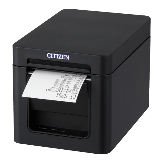
1. GENERAL OUTLINE The CT-S251 line thermal printer series is designed for use with a broad array of terminal equipment including data, POS, and kitchen terminals. These printers have extensive features so they can be used in a wide range of applications. -
Page 13: Unpacking
1.2 Unpacking Make sure the following items are included with your printer. Printer: CD-ROM: AC power cord: Quick Start Guide: Sample paper roll: AC adapter: 1 roll AC power cord AC adapter Sample paper (36AD2/37AD5) roll Printer... -
Page 14: Basic Specifications
1.4 Basic Specifications Item Specifications Model CT-S251 Print method Line thermal dot print method Print widths 54.5 mm/436 dots, 54 mm/432 dots, 52.5 mm/420 dots, 48.75 mm/390 dots, 48 mm/384 dots, 45 mm/360 dots, Factory setting: 54 mm Dot density 8 ×... -
Page 15: Explanation Of Printer Parts
*2: Characters appear small because the dimensions include a blank area surrounding each character. *3: Compliant if the Citizen Systems AC adapter (36AD2/37AD5) is used. 2. EXPLANATION OF PRINTER PARTS 2.1 Printer Appearance Names of parts Paper cover Cover open lever... -
Page 16: Feed Button
FEED button Press this button to feed paper. In case of a cutter lock, remove the cause of the lock, close the paper cover, and then press the FEED button. The printer enters the mode for setting memory switches and running self test. Refer to 4.3 Self Test Refer to 5.3 Manual Setting of Memory Switches Operation panel... - Page 17 Rear connectors Interface connector Cash drawer kick-out (serial, USB, etc.) connector Power connector Interface connector (serial, parallel, USB, etc.) Connects to the interface cable. Cash drawer kick-out connector Connects to the cable from the cash drawer. Power connector Connects to the AC adapter cable.
-
Page 18: Inside The Paper Cover
2.2 Inside the Paper Cover Print head (thermal) Paper near-end (PNE) sensor Button to change paper near-end sensor Paper end (PE) sensor Platen Auto cutter Platen Feeds the paper. Do not remove the platen except to do maintenance. Paper near-end (PNE) sensor Detects when the paper is near the end of the roll. -
Page 19: Other Built-In Functions
2.3 Other Built-in Functions Buzzer Buzzes when errors occur or when operations or command operations are performed. Refer to 4.5 Error Indications User memory You can save user-defined logo and character data in this memory. Data remains stored in this memory even if the printer is turned off. For information on how to save data, refer to the Command Reference. - Page 20 CAUTION Before configuring the top margin suppression setting, first remove any partially cut paper from the printer. Failure to do so can cause the cut paper to be torn off by the next print operation, which can cause printer trouble. ...
-
Page 21: Setup
3. SETUP 3.1 Connecting the AC Power Cord Turn off the power. Connect the power connector to the AC adapter cable connector. Next, connect the AC power cord to the AC inlet, and insert the plug into an electric outlet. Power connector Cable connector AC adapter... -
Page 22: Connecting Interface Cables
3.2 Connecting Interface Cables Turn off the power. Orient the interface cable correctly and insert it into the interface connector. Serial Bluetooth + USB Ethernet+USB Wireless LAN + LAN CAUTION When disconnecting the cable, always hold the connector. Be careful not to insert the USB cable into the cash drawer kick-out connector. ... -
Page 23: Bluetooth Interface Board
3.3 Bluetooth Interface Board Bluetooth status LED Status LED The LED on the Bluetooth interface board on the rear of the printer indicates the status below. Status Description LED Status Detection Standing by for standby detection and (Discoverable) connection Connection Standing by for standby connection... - Page 24 B: Configuring pairing settings Normally, selecting the printer during device detection will transition directly to pairing settings. CAUTION Some host PC configurations and models may not transition directly to pairing settings after the printer is selected during device detection. The operation required to configure pairing settings depends on whether SSP (secure simple pairing) is enabled on the host PC.
-
Page 25: Ethernet (Lan) Interface Board
3.4 Ethernet (LAN) Interface Board This section provides an overview of the Ethernet (LAN) interface board. For details about this board, refer to the separate manual. Panel button operation Board operations are performed using the panel button on the Ethernet board. You can use the button to print setup information. - Page 26 LED Functions The tables below explain how to interpret LED indications. 1. Network transmission speed Transmission speed LED (green) 100Mbps 10Mbps/Not connected Unlit 2. Network status Status LED (yellow) Connected Not connected Unlit Data transmission in Flashing progress Changing network settings You can use a web browser to access a special settings page to check and change board settings.
- Page 27 This displays the page to display the current status. Click the "Edit" button to display the "Print Server Configuration" page shown below. For details about settings, refer to the separate manual. — 24 —...
-
Page 28: Wireless Lan Interface Board
3.5 Wireless LAN Interface Board This section provides an overview of the wireless LAN interface board. For details about this board, refer to the separate manual. Panel button operation Board operations are performed using the panel button on the rear of the LAN board. Panel button ... -
Page 29: Led Functions
LED Functions The tables below explain how to interpret LED indications. 1. Wired LAN transmission speed Transmission speed LED (green) 100Mbps 10Mbps/Not connected Unlit 2. Wired LAN connection/transmission status Connection status LED (yellow) Connected Not connected Unlit Data transmission in Flashing progress 3. - Page 30 Web Manager The wireless LAN interface board has a Web Manager function that can be used to connect to the board with a web browser and change board settings. Starting up Web Manager Start up a web browser. In the address field, input the board's IP address and then press [Enter]. HOME Screen This is the Web manager home screen.
- Page 31 CONFIG Screen This will display the Login dialog box shown below. Log in as an administrator and then configure wireless LAN interface board settings. User Name Input a board administrator user name. (Initial setting: admin) Password Input the administrator user password. (Initial setting: admin) ...
-
Page 32: Connecting The Cash Drawer
3.6 Connecting the Cash Drawer Turn off the power. Confirm the orientation of the cash drawer kick-out cable connector and connect it to the cash drawer kick-out connector at the back of the printer. Remove the screw for the ground wire. Screw the cash drawer’s ground wire to the body of the printer. - Page 33 (1) Connector pin configuration Signal Function Frame ground Connector used: TM5RJ3-66 (Hirose) or DRAWER1 Cash drawer 1 drive signal equivalent DRSW Cash drawer switch input Applicable connector: Cash drawer drive power supply TM3P-66P (Hirose) or equivalent DRAWER2 Cash drawer 2 drive signal Signal ground (common ground on circuits) (2) Electric characteristics...
-
Page 34: Precautions For Installing The Printer
3.7 Precautions for Installing the Printer This printer can only be positioned horizontally. It cannot be positioned vertically or on a wall. Horizontal position Vertical position CAUTION Do not use the printer under the following conditions. Avoid locations subject to vibration or instability. ... -
Page 35: Adjusting The Paper Near-End Sensor
3.8 Adjusting the Paper Near-end Sensor Change the settings of the paper near-end sensor to set the position at which the near-end of the paper is detected. Gently press the paper near-end sensor with your finger. Keep the paper near-end sensor pressed as you move it left and right. The sensor positions are shown below for the various diameters of the paper roll used. -
Page 36: Loading Paper
3.9 Loading Paper Turn on the power. Press up on the cover open lever to open the paper cover. CAUTION When pressing up on the lever, take care that you do not pinch your fingers in the gap above the top of the lever. Load the paper roll so that the printable side of the paper is facing up, as shown by arrow A. -
Page 37: Installing A Driver
Install the driver required by your printer. For information about driver installation, functions, and operations, see the information provided on the CD-ROM for each driver. Visit the site below to download the latest driver versions and information. http://www.citizen-systems.co.jp/english/support/download/printer/driver/ 3.11 Precautions for Creating Applications and Practical Operations If printing is done immediately after the paper is partially cut and torn off, the top of the next print out may be distorted. -
Page 38: Maintenance And Troubleshooting
MAINTENANCE AND TROUBLESHOOTING 4.1 Periodic Cleaning A dirty print head or platen may reduce printing quality or cause malfunctions. We recommend cleaning the printer periodically (every 2 to 3 months) as shown below. Turn off the power. Press up on the cover open button to open the paper cover. Wait a few minutes until the print head cools. -
Page 39: Clearing A Cutter Error
4.2 Clearing a Cutter Error The CUTTER LED flashes, the PAPER LED and COVER LED light, and the auto cutter blade remains extended because a foreign object or paper jam is obstructing it. If a cutter error occurs, clear the locked cutter as described below. Turn off printer power. -
Page 40: Self Test
4.3 Self Test You can use self test to check for printer problems. Performing a self test operation While paper is loaded, press and hold the FEED button while turning the power on. Hold the FEED button down for about one second until the buzzer sounds. Release the button to start self test. -
Page 41: Hexadecimal Dump Printing
4.4 Hexadecimal Dump Printing Print received data in hexadecimal. If problems such as missing or duplicated data occur, this function allows you to check whether or not the printer is receiving data correctly. How to do hexadecimal dump printing Load paper. While the paper cover is open, hold down the FEED button as you turn on printing power. -
Page 42: Error Indications
4.5 Error Indications Paper end, paper near-end The end of the roll of paper is detected at two stages, paper near-end and paper- end. When paper near-end is detected, the PAPER LED flashes. Prepare a new paper roll. When paper end is detected, the PAPER LED lights and the buzzer sounds. Load a new paper roll. - Page 43 The status display for various messages is shown below. Status PAPER LED CUTTER LED COVER LED SERVICE LED Buzzer Paper near-end Unlit Unlit Unlit — Paper-end Unlit Unlit Unlit Cover open Unlit Unlit Unlit Cover open II Unlit Unlit Unlit Cutter locked Unlit Unlit...
-
Page 44: Paper Jams
4.6 Paper Jams Take care to avoid obstruction of the paper outlet and paper jamming around the outlet during printing. If paper cannot get out of the printer, it can roll up on the platen inside the printer and cause an error. If the paper wraps around the platen, open the paper cover and carefully pull the paper out. -
Page 45: Other
5. OTHER 5.1 External Views and Dimensions (Unit: mm) — 42 —... -
Page 46: Printing Paper
5.2 Printing Paper Use the paper shown in the following table or paper of the same quality. Paper type Product name Recommended TF50KS-E2D, TF50KS-E or TF60KS-E from Nippon Paper thermal roll paper PD150R or PD160R from Ohji Paper P220AG, HP220A, HP220AB-1, or P220AB from Mitsubishi Paper (Unit: mm) Paper width 58 Printable side... -
Page 47: Manual Setting Of Memory Switches
5.3 Manual Setting of Memory Switches Memory switches are used to set various printer settings. Memory switches can be set manually, or by utilities or commands. This section explains how to perform manual settings. For information on how to set the memory switches using commands, please refer to the Command Reference. - Page 48 Press the FEED button. A setting is printed each time the FEED button is pressed in order through the cycle. When the current settings are printed, the COVER LED lights. Press the FEED button until the setting you want is printed. Press the FEED button for at least two seconds.
- Page 49 The function of each memory switch is shown in the following table. (Shaded values are factory settings.) Switch no. Function MSW1-1 Power ON Info Valid Not Send MSW1-2 Buffer Size 4K bytes 45 bytes MSW1-3 Busy Condition Full/Err Full MSW1-4 Receive Error Print“?”...
- Page 50 Switch no. Function MSW6-2 Character Space Invalid Valid MSW6-3 USB Power Save Invalid Valid MSW6-4 Reserved Fixed — MSW6-5 Reserved Fixed — MSW6-6 Reserved Fixed — MSW6-7 Reserved Fixed — MSW6-8 Reserved Fixed — Switch no. Function Initial setting Setting value MSW7-1 Baud Rate 9600 bps...
- Page 51 Switch no. Function Initial setting Setting value MSW13-1 Security/Target Low/All Low/All, Mid/All, Mid/Paired only, Hi/All, Hi/Paired only MSW13-5 BT Device Scan Discoverable No Response, Discoverable MSW13-6 Auto Reconnect Valid Invalid, Valid Note: *: If print data is very dense, the print head is hot, data transmission is slow, or some other conditions, the motor and printing may occasionally stop which causes white stripes in the printout.
- Page 52 CT-S251_UM_103EN A93403E-1508 October 2015...
Need help?
Do you have a question about the CT-S251 and is the answer not in the manual?
Questions and answers