Citizen CT-S281 User Manual
Line
Hide thumbs
Also See for CT-S281:
- Quick start manual (41 pages) ,
- Service manual (39 pages) ,
- Command reference manual (512 pages)
Table of Contents
Advertisement
Quick Links
Advertisement
Table of Contents

Related Manuals for Citizen CT-S281


Summary of Contents for Citizen CT-S281
- Page 1 LINE THERMAL PRINTER MODEL CT-S281 User’s Manual...
-
Page 2: Declaration Of Conformity
●Bluetooth is a registered trademark of Bluetooth SIG, Inc. ●All other trademarks are the property of their respective owners. ●Citizen Systems use these trademarks in accordance with the license of relevant owners. Copyright c 2016 by CITIZEN SYSTEMS JAPAN CO., LTD. - Page 3 IMPORTANT: This equipment generates, uses, and can radiate radio frequency energy and if not installed and used in accordance with the instruction manual, may cause interference to radio communications. It has been tested and found to comply with the limits for a Class B computing device pursuant to Subpart J of Part 15 of FCC Rules, which are designed to provide reasonable protection against such interference when operated in a commercial environment.
-
Page 4: General Precautions
● Note that CITIZEN SYSTEMS is not responsible for any operation results regardless of missing, error, or misprinting in this manual. ● Note that CITIZEN SYSTEMS is not responsible for any trouble caused as a result of using options or consumables that are not specified in this manual. - Page 5 SAFETY PRECAUTIONS ... WHICH SHOULD BE STRICTLY OBSERVED Before using this product for the first time, carefully read these SAFETY PRECAUTIONS. Improper handling may result in accidents (fire, electric shock or injury). In order to prevent injury to operators, third parties, or damage to property, special warning symbols are used in the User’s Manual to indicate important items to be strictly observed.
- Page 6 Should it occur, immediately turn the printer off, unplug it from the supply outlet, and call your local Citizen Systems dealer. Do not handle the printer in the following ways: ■ Do not allow the printer to sustain strong impacts or hard jolts (e.g., trampling, dropping, striking with a hard edge).
- Page 7 CAUTION Do not use the printer under the following conditions. ■ A state subject to vibration or unstable state. ■ A state with this product slanted. • Otherwise dropping may cause injury. • Poor print quality may occur. ■ A state where the printer ventilation holes are obstructed by a nearby wall or other equipment.
- Page 8 • Neglecting these cautions may cause wires or insulation to break, which could result in leakage, electric shock, or printer failure. If the power cord sustains damage, contact your Citizen Systems dealer. ■ Do not leave things around the supply outlet.
- Page 9 ■ Do not touch any of the moving parts (e.g., paper cutter, gears, active electrical parts) while the printer is working. ■ In case of trouble do not attempt to repair the printer. Ask Citizen Systems service for repair. ■ Be careful that the printer cover does not entrap your hands or fingers.
-
Page 10: Daily Maintenance
Be careful when you make a communication using the Bluetooth function. ■ Note that Citizen Systems is not responsible for any leakage of data or information in the communication using the Bluetooth function. ■ The frequency band used in this printer is also used for home appliances such as... -
Page 11: Table Of Contents
THE TABLE OF CONTENTS 1. GENERAL OUTLINE ..............9 1.1 Features ..................9 1.2 Unpacking ..................10 1.3 Model Classification ..............10 1.4 Basic Specifications ..............11 2. EXPLANATION OF PRINTER PARTS........12 2.1 Printer Appearance ..............12 2.2 Paper Cover Inside ............... 14 2.3 Other Built-in Functions ............... -
Page 12: General Outline
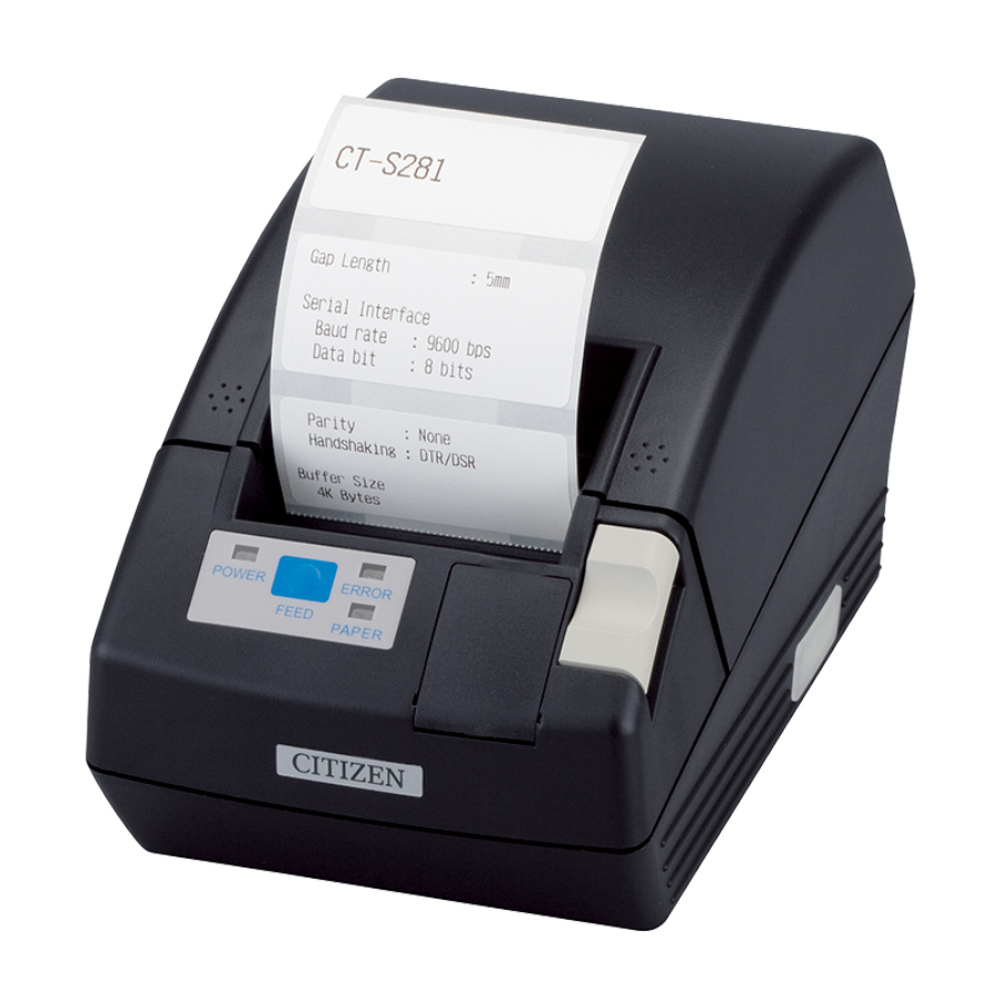
1. GENERAL OUTLINE The CT-S281 is a thermal line printer designed for use with a broad array of terminal equipment including, data, POS, and kitchen terminals. With extensive features, it can be used in a wide range of applications. 1.1 Features ●... -
Page 13: Unpacking
1.2 Unpacking When unpacking the printer, confirm that the following are provided: ● Printer: ● AC adapter: ● AC power cord: ● Sample paper roll: 1 roll ● USB cable clamp(USB Interface model): ● Operation panel(for wall mounting): ● Quick start guide: ●... -
Page 14: Basic Specifications
UL, C-UL, FCC Class B TUV, GS, CE marking Radio Law BT model (Mark indicating technical standards conformity), BD model (Mark indicating technical standards conformity, FCC, R&TTE) *Represents the safety standards acquired when CITIZEN SYSTEMS-made adapters (28AD series) are used. — 11 —... -
Page 15: Explanation Of Printer Parts
2. EXPLANATION OF PRINTER PARTS 2.1 Printer Appearance Printer cover Cover open button Cutter gear cover Power switch Operation panel ● Printer cover Paper is located inside this cover. ● Cover open button To refill or replace paper, open the paper cover by pushing this button. ●... - Page 16 ● ERROR LED Lights or blinks when paper is empty or in case of a failure. The interval length of blinking shows the type of error. ● PAPER LED Lights when there is no paper or the paper is low with the optional PNE sensor. ●...
-
Page 17: Paper Cover Inside
2.2 Paper Cover Inside Paper feed roller Paper near-end sensor Auto cutter Paper-end sensor Manual cutter Print (thermal) head ● Auto Cutter Cuts the paper when software command is sent to the printer. Cutting method could be partial cut or full cut, “Partial Only”is set to valid by the default memory switch 4-8, so that the full cut command will execute as partial cut operation. -
Page 18: Preparation
3. PREPARATION 3.1 Connecting the AC Adapter and AC Power Cord 1. Turn off the printer power. 2. Plug in the cable connector of the AC adapter to the power connector at the rear of the printer. 3. Connect the AC power cord to the inlet of AC adapter, and insert the AC power- cord plug into a suitable wall outlet. -
Page 19: Connecting Interface Cables
3.2 Connecting Interface Cables Turn off the printer and unplug the power connector. Then follow the procedure for interface cable connection. Orient the interface cable terminal correctly and insert it into the interface connector. USB cable clamp USB Interface Serial Interface CAUTION! ●... -
Page 20: Bluetooth Connection
If the host has no SSP feature, a passkey may be requested. Enter a passkey. The device name to be found and the passkey to be entered are as follows: Device name: CITIZEN SYSTEMS Passkey: Enter the last four digits of the address printed by self-printing. - Page 21 3.3.2 Reconnect Request (BD model only) With BD model,”MSW13-6 Reconnect Request” feature is provided for iOS device. This feature is set to be valid at the time of shipment. If this feature is valid, the printer tries to connect to the host connected last in the following cases.
-
Page 22: Connecting The Cash Drawer
Cash drawer cable connector CAUTION! ● Only drawer for 8.5V dedicated to Citizen CT-S281 BD can operate. Do not connect the drawer for 24V available on the market. (1) Connector Pin Configuration Connector used: Signal... -
Page 23: Installing The Printer
3.5 Installing the Printer The printer can be installed horizontally or mounted vertically on the wall. At the time of shipment, the printer is set for horizontal installation. To install the printer on the wall, put the accessory operation panel on to the original one. -
Page 24: Setting Dip Switch (Only Serial Interface Type)
3.6 Setting DIP Switch (Only serial interface type) DIP switch is provided only for serial interface specification. The DIP switch is located at the bottom of the paper holder. To set the DIP switch open the printer cover and remove the paper. Initial Switch No. -
Page 25: Adjusting The Paper Near-End Sensor
3.7 Adjusting the Paper Near-end Sensor Move the paper near-end sensor lever to forward or backward. The position to be set varies in accordance with the paper roll as shown in the following table. unit: mm Lever Position External Diameter of Paper Poll Remainder φ24 φ34 CAUTION! -
Page 26: Selecting Paper Type
3.8 Selecting Paper Type Paper type selection is available by the combination of memory switches SW4- 4 and SW4-5 by the used of “Memory Switch Select Mode”. In addtion, the following procedure is available. 1 Enter Selecting Paper Type mode. 1)Open the printer cover and remove paper. - Page 27 Black Mark sensor Black Mark paper Label light receiving sensor sensor adjuster Label paper sensor Label light emitting sensor Level indicator adjuster Sensor adjuster cover Figure 1 1 Enter Adjusting Paper Sensor mode. Open the printer cover, remove paper, and then set the printer power switch to ON.
-
Page 28: Full Cutting Label Paper
3.10 Full cutting label paper When full-cutting the label paper with the printer installed horizontally,Be sure that the guide plate is mounted on the paper exit of the printer cover. (This guide plate was set to the printer at the time of factory shipment.) The Guide Plate prevents cut paper from dropping in the printer. -
Page 29: Maintenance And Troubleshooting
4. MAINTENANCE AND TROUBLESHOOTING 4.1 Setting/Replacing Paper Rolls 1. Press the cover open button down. 2. Open the printer cover. 3. Insert a paper roll with the print surface facing down as shown on the figure below and pull the paper end out of the printer. 4. -
Page 30: Removing Jammed Paper
4.2 Removing Jammed Paper 1. Turn the printer power off. 2. Open the printer cover. If the cutter blade remains protruded with paper jammed, do not open the printer cover forcibly. Referring to section 4.4, restore the blade to the normal position and then open the cover. 3. -
Page 31: When The Paper Cover Cannot Be Opened
4.4 When the Printer Cover Cannot Be Opened Cutter lock error may occur with the Auto Cutter due to dropping of foreign object, paper jam, etc. If the cutter blade remains protruded with cutter lock error, the printer cover does not open. The Auto Cutter can also be restored to the initial position by turning the printer on again or by pressing the FEED button, when the memory SW3-1 is set to OFF. -
Page 32: Self-Printing
4.5 Self-printing Insert paper into the printer. With the FEED button pressed and held, turn the printer power on, keep the FEED button held for about 1 second, and then release the FEED button. The printer starts self-printing. The printer prints model name, version, DIP switch setting, memory switch setting, and built-in fonts. -
Page 33: Error Indication
4.7 Error Indication ● Paper-end Paper empty is detected in two steps: paper-end and paper near-end(factory option). It causes the PAPER LED to light. If paper-end is detected, replace the paper roll. ● Cover open error When the printer cover is opened, Printer cover open is detected and the ERROR LED goes on. -
Page 34: Other
The LED status of each error including the above is shown below. Status POWER LED ERROR LED PAPER LED Paper-end Lights Lights Lights Paper near-end Lights Turning off Lights Cover open error Lights Lights Turning off Cover open error *1 Lights Turning off Cutter lock error... -
Page 35: Manual Setting Of Memory Switch
5.2 Manual Setting of Memory Switch Memory switches can be set manually or by a command. For manual setting, refer to the next page. The function of each memory switch is shown in the following table. (The white-on-black characters are factory setting.) Switch No. - Page 36 Switch No. Setting Default Set Values Memory SW7-1*12 Baud Rate 9600 bps 1200 bps, 2400 bps, 4800 bps, 9600 bps, 19200 bps, 38400 bps SW7-2 Data Length 8bits 7bits, 8bits SW7-3 Stop Bit 1bit 1bit, 2bits SW7-4 Parity NONE NONE, EVEN, ODD SW7-5 Flow Control DTR/DSR...
- Page 37 *1: For Bluetooth communication, 64k (BT model) or 256K (BD model) is available. *2: Set to be invalid when Blackmark paper/label paper is selected by MSW4-4 and label detection is selected by MSW4-5. *3: When paper length setting is assigned as a command, use the command when specifying paper layout.
- Page 38 Manual Setting of Memory Switch (Memory SW) The memory switch can be selected, changed, or written by the combination of three actions: pressing the FEED button, pressing and holding the FEED button, and opening or closing the printer cover. Entering memory switch setting mode. Set paper to the printer and keep the printer cover open.
-
Page 39: Printing Paper
Saving the setting and exiting the memory switch setting mode Press the FEED button shortly to move to “Write/Factory Setting”. Then press and hold the FEED button. The printer prints the content of new setting and exits the memory switch setting mode to return to the normal standby state. - Page 40 When using “label paper” with CT-S281XL/OL, refer to the following. Use the following paper or the equivalent paper. Paper type Product name Recommended thermal label paper HD75 from Nippon Paper 150HBW from Ricoh b) Label paper Full cut position Paper feeding Unit: mm direction Mark...
- Page 41 c) Black mark paper (BM paper) Cut position Printable area Paper feeding direction Black Mark (printed on the reverse) Unit: mm Mark Item Dimensions Right edge of black mark 15 or more Left edge of black mark 0 to 1.5 Black mark height Cut position in black mark 2.5 Top margin...
- Page 42 TE74905-05F 1.05E-1609 September 2016...
Need help?
Do you have a question about the CT-S281 and is the answer not in the manual?
Questions and answers