Alto-Shaam AR-6G Installation, Operation And Maintanance
Gas
Hide thumbs
Also See for AR-6G:
- Specification sheet (2 pages) ,
- Specifications (2 pages) ,
- Installation, operation and maintenance manual (34 pages)
Table of Contents
Advertisement
Quick Links
R o t i s s e r i e
G a s
Models:
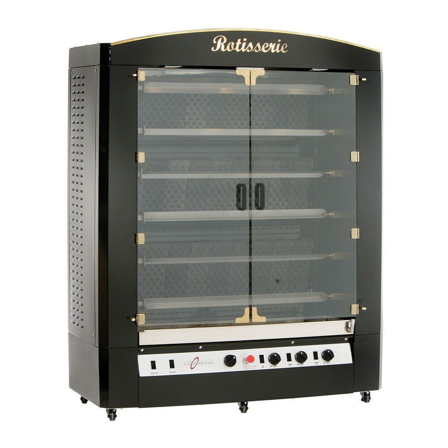
AR-6G
• INSTALLATION
• OPERATION
• MAINTENANCE
W164 N9221 Water Street • P.O. Box 450 • Menomonee Falls, Wisconsin 53052-0450 USA
PHONE: 262.251.3800 • 800.558.8744
/
FAX: 262.251.7067 • 800.329.8744
.
.
.
USA
CANADA
U
S
A
ONLY
www.alto-shaam.com
MN-28648 • Rev 3 (11/14)
.
.
.
p r i n t e d i n u
s
a
Advertisement
Table of Contents

Subscribe to Our Youtube Channel
Related Manuals for Alto-Shaam AR-6G


Summary of Contents for Alto-Shaam AR-6G
- Page 1 R o t i s s e r i e G a s Models: AR-6G • INSTALLATION • OPERATION • MAINTENANCE W164 N9221 Water Street • P.O. Box 450 • Menomonee Falls, Wisconsin 53052-0450 USA PHONE: 262.251.3800 • 800.558.8744 FAX: 262.251.7067 • 800.329.8744...
-
Page 2: Table Of Contents
Care and Cleaning Delivery . . . . . . . . . . . . . . . . . . . . . . . . . . . . . . . . . . 1 Unpacking . -
Page 3: Delivery
Additional model. Contact the Alto-Shaam Tech Team Service manuals are available from the Alto-Shaam Department if you have any questions concerning Tech Team Service Department. -
Page 4: Safety Procedures And Precautions
SAFETY PROCEDURES AND PRECAUTIONS Knowledge of proper procedures is essential to the 1. This appliance is intended to cook, hold safe operation of electrically and/or gas energized or process foods for the purpose of human equipment. In accordance with generally accepted consumption. -
Page 5: Installation
I N S T A L L A T I O N C O M M O N S P E C I F I C A T I O N S A C C E S S O R I E S A R-6G Overall height 78-1/8"... -
Page 6: Dimension Drawings
I N S T A L L A T I O N T E C H N I C A L S P E C I F I C A T I O N S DIMENSIO NS ( h x w x d 50-7/8"... -
Page 7: Technical Components
I N S T A L L A T I O N T E C H N I C A L C O M P O N E N T S S P ITS MO TO R S W IT CH Number Number BU LB S... -
Page 8: Installation Codes & Standards
I N S T A L L A T I O N S I T E I N S T A L L A T I O N INSTALLATION CODES & STANDARDS The following codes and standards are required for installation of this appliance: AIR SUPPLY, ELECTRICAL CONNECTIONS, WATER CONNECTIONS, GAS CONNECTIONS, GAS EXHAUST, AND WASTE WATER DISCHARGE. -
Page 9: Positioning Requirements
I N S T A L L A T I O N S I T E I N S T A L L A T I O N POSITIONING REQUIREMENTS ❑ Allow a 20" (508mm) clearance at the top of the appliance for free air movement and for the vent(s) ❑ In order to ensure proper ventilation, a minimum located at the top. -
Page 10: Ventilation Instructions
I N S T A L L A T I O N V E N T I L A T I O N I N S T R U C T I O N S D A N G E R An adequate ventilation system is required for commercial Installation, air adjustment and/or cooking equipment. -
Page 11: Electrical
I N S T A L L A T I O N E L E C T R I C A L An electrical wiring diagram is located under the Wire size for the main incoming power to the unit must access panel beneath the drip tray of the appliance. -
Page 12: Air Supply
I N S T A L L A T I O N A I R S U P P L Y AIR SUPPLY AIR ADJUSTMENTS Installation of this appliance must include a The appliance can be field converted from one type of gas provision for an adequate flow of fresh air for gas to another (natural gas to propane or vice versa). -
Page 13: Gas Connections
1.12 kPa Pressure GAS SPECIFICATIONS Max. Connected 14.0" W.C. 3.5 kPa Pressure NATURAL GAS PROPANE GAS Propane Gas AR-6G 195,000 Btu/hr. 195,000 Btu/hr. Min. Connected 11.0" W.C. 1.99 kPa Pressure INSTALLATION REQUIREMENTS Max. Connected GAS CONNECTION: 3/4" NPT 14.0" W.C. - Page 14 I N S T A L L A T I O N G A S C O N N E C T I O N S The installation of this appliance must be completed by Close the individual manual shut-off valve to isolate a qualified installer familiar with the local codes and the appliance from the gas supply piping system during regulations governing the installation of commercial gas...
-
Page 15: Securing Electrical Access Cover
I N S T A L L A T I O N G A S C O N N E C T I O N S The minimum size of the gas piping or flexible connector When a quick disconnect device and flexible connector are is 3/4" (19mm). For long runs of gas piping, the pipe used, a restraining device must be installed to limit the diameter must conform to the tables in the National Fuel movement of the appliance in order to prevent damage to Gas Code, ANSI/NFPA Z223.1... -
Page 16: Leak Testing
I N S T A L L A T I O N L E A K T E S T I N G If a pressure leak test above 1/2 psi is to be conducted on helpful; however, this type of detector can be oversensitive. the building supply gas piping, the shutoff gas valve and Electronic detectors may indicate false leaks from other appliance inlet gas supply line must be disconnected from... -
Page 17: Operating Instructions
O P E R A T I N G I N S T R U C T I O N S B U R N E R L I G H T I N G I N S T R U C T I O N S Verify appliance connection to the correct gas source. -
Page 18: Controls
O P E R A T I N G I N S T R U C T I O N S C O N T R O L S The MAIN POWER switch is located on the left side ... -
Page 19: Placement & Adjustment Of Spits
O P E R A T I N G I N S T R U C T I O N S P L A C E M E N T & A D J U S T M E N T O F S P I T S To place the spit into the appliance insert the “T”... -
Page 20: Skewer Preparation & Loading
O P E R A T I N G I N S T R U C T I O N S S K E W E R P R E P A R A T I O N & L O A D I N G The appliance is furnished with six, removable skewers, Slide the bird down along the spit toward the disc shaped each with 37"... -
Page 21: Care And Cleaning
C A R E A N D C L E A N I N G E Q U I P M E N T C A R E The cleanliness and appearance of this When cooking has been completed, stop the motor equipment will contribute considerably for each corresponding spit and remove the spit by to operating efficiency and savory,... -
Page 22: Cleaning & Reseasoning Of Cast Iron Tiles
C A R E A N D C L E A N I N G C A U T I O N D A N G E R THIS SECTION IS PROVIDED FOR THE ASSISTANCE DISCONNECT UNIT FROM OF QUALIFIED SERVICE TECHNICIANS ONLY AND POWER SOURCE BEFORE IS NOT INTENDED FOR USE BY UNTRAINED OR CLEANING OR SERVICING. -
Page 23: Service
Inlet pressure too low. Contact qualified gas specialist. Alto-Shaam has established a twenty-four hour emergency service call center to offer immediate customer access to a local authorized service agency outside of standard business hours. The emergency service access in provided exclusively for Alto-Shaam equipment and is available throughout the United States through the use of Alto-Shaam’s toll-free number. -
Page 24: Full Assembly View & Part List
S E R V I C E F U L L A S S E M B L Y - F R O N T V I E W I T E M PA RT N O . D E SC R I PT I ON Q TY IT E M P A R T N O . -
Page 25: Final Floor Assembly View & Part List
S E R V I C E F I N A L F L O O R A S S E M B L Y - F R O N T V I E W DETAIL J DETAIL J 1 : 2 23 24 F I N A L F L O O R A S S E M B L Y - B A C K V I E W DETAIL H... - Page 26 S E R V I C E F I N A L F L O O R A S S E M B L Y - F R O N T & B A C K V I E W I T E M P AR T NO .
-
Page 27: Motor Mount Assembly View & Part List
S E R V I C E M O T O R M O U N T A S S E M B L Y Notes: • Must use arbor press or vise clamp press to fit motor shaft to motor (see drawing for spacing). •... -
Page 28: Top Assembly View & Part List
S E R V I C E T O P A S S E M B L Y I T E M P AR T NO . DE S CR IP T I ON QT Y I T EM P A R T N O . D E S C R I P T I O N Q T Y SC-2661... -
Page 29: Gas Plumbing Assembly & Part List
S E R V I C E G A S P L U M B I N G A S S E M B L Y DETAIL A 1 : 1 IT E M P A R T N O . D E S C R I P T I O N Q T Y VA-25527... -
Page 30: Bottom Assembly View & Part List
S E R V I C E B O T T O M A S S E M B L Y P a r t n u m b er s a n d d raw i n g s a r e su bj e c t to c ha n g e w i th ou t n ot i c e . MN- 2 8648 •... - Page 31 15A CLASS G FUSE KN-34858 KNOB, INDICATOR TN-33460* TRANSFORMER, STEP DOWN PE-36695 PANEL OVERLAY AR-6G BK-3019* T-BLOCK 5007975* WIRE SET 120V * NOT SHOWN P a r t n u m b er s a n d d raw i n g s a r e su bj e c t to c ha n g e w i th ou t n ot i c e .
-
Page 32: Bulb Replacement
S E R V I C E B U L B R E P L A C E M E N T I N S T R U C T I O N S TO REPLACE CAVITY BULBS: B & C B Pull bulb out A Remove the four screws D Re-install glass cover and... -
Page 33: Clearances
CLEARANCES: All clearances must conform with the standards set by RIGHT SIDE CLEARANCE: ______________________ Alto-Shaam as indicated in the installation manual. Standards include a minimum 20" (508mm) clearance from LEFT SIDE CLEARANCE: ______________________ any heat-producing device such as an open burner range, flat top grille, fryer, steamer, etc. Also make sure sufficient... - Page 34 MN- 2 8648 • R ev 3 (11 /14) • A R-6 G Rotis seri e Op erati on & Care Ma nual • 32...
-
Page 35: Transportation Damage And Claims
LIMITED WARRANTY Alto-Shaam, Inc. warrants to the original purchaser only that any original part that is found to be defective in material or workmanship will, at Alto-Shaam's option, subject to provisions hereinafter stated, be replaced with a new or rebuilt part.
Need help?
Do you have a question about the AR-6G and is the answer not in the manual?
Questions and answers