
Related Manuals for Alto-Shaam AR-7T


Summary of Contents for Alto-Shaam AR-7T
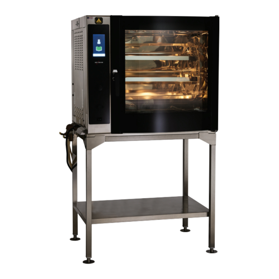
- Page 1 Service Manual Self-Cleaning Rotisserie Oven including Optional Holding Cabinet AR-7T AR-7HT MN-39243 REV. 01 2/19 alto-shaam.com...
-
Page 2: Manufacturer's Information
© Copyright 2/19 by Alto-Shaam, Inc. All rights reserved. This manual or any portion thereof may not be reproduced or used in any manner whatsoever without the express written permission of Alto-Shaam, Inc. Trademarks All trademarks referenced in this documentation are the property of their respective owners. -
Page 3: Foreword
Call 800-558-8744 to reach our 24-hour emergency service call center for immediate access to local authorized service agencies outside standard business hours. The emergency service access is provided exclusively for Alto-Shaam equipment and is available throughout the United States through Alto-Shaam’s toll free number. - Page 4 OREWORD This page intentionally left blank. Se lf -Cl e an i n g Ro ti s se r i e Ove n Se r vi ce Ma n u al M N- 39 2 4 3 Rev 1 2/ 1 9 ▪...
-
Page 5: Table Of Contents
Troubleshooting AR-7T Error Codes ......51 The Oven will not Power Up ......53 The Oven will not Heat . - Page 6 OREWORD Liquid Cleaner Pump Inoperable ..... 61 The Oven Water Heater will not Heat ....62 Schematics Se lf -Cl e an i n g Ro ti s se r i e Ove n Se r vi ce Ma n u al...
-
Page 7: Safety
AFETY The Meaning of Signal Words This manual contains signal words where needed. These signal words must be obeyed to reduce the risk of death, personal injury, or equipment damage. The meaning of these signal words is explained below. DANGER Danger indicates a hazardous situation which, if not avoided, will result in serious injury or death. -
Page 8: Appliance Description And Intended Use
AFETY Appliance Description and Intended Use Appliance This Alto-Shaam rotisserie oven is an electric-powered oven with programmable Description touchscreen control that includes multi-level cooking for preheat, cooking, holding, and cool-down stages. It includes a self-cleaning wash system with built- in sanitizing cycle. Seven angled spits are included; a variety of spits are offered as options. -
Page 9: Safety Precautions
AFETY Safety Precautions Before you begin Read and understand all instructions in this manual. Electrical precautions Obey these electrical precautions when using the appliance: ▪ Various electrical configurations of the rotisserie are available. Always match the power source with the power rating on the rotisserie’s data tag. ▪... - Page 10 Keep this manual and all supplied instructions, diagrams, schematics, parts lists, notices, and labels with the appliance if the appliance is sold or moved to another location. ▪ Contact Alto-Shaam for additional training if needed. Operator Only trained personnel with the following operator qualifications are permitted qualifications to use the appliance: ▪...
- Page 11 Only trained personnel are permitted to service or repair the appliance. Repairs that are not performed by an authorized service partner or trained technician, or appliance the use of non-factory parts, will void the warranty and relieve Alto-Shaam of all liability. ▪...
- Page 12 AFETY This page intentionally left blank. Se lf -Cl e an i n g Ro ti s se r i e Ove n Se r vi ce Ma n u al M N- 39 2 4 3 Rev 1 2/ 1 9 ▪...
-
Page 13: Operation
PERATION How to Turn On and Turn Off the Oven Before you begin The oven must be connected to electric power. Turning on the oven To turn on the oven, do the following. Step Action the power switch to the ON (l) position AR-TS-006091 The oven is now on. -
Page 14: How To Update The Software
PERATION How to Update the Software Before you begin Make sure ▪ The oven is turned on. ▪ The oven is idle and not currently in a cook or clean sequence. ▪ You do not remove the USB drive during the update process. ▪... - Page 15 PERATION Continued from previous page Step Action Insert the USB drive into the port AR-TS-005774 NOTICE Do not remove the USB drive during the update process. Touch the download new software icon for the full oven update. touch To update only the interface board, the interface board icon ▪...
-
Page 16: How To Restore Factory Defaults
PERATION How to Restore Factory Defaults Before you begin the oven is turned on. Make sure Procedure To restore factory defaults, do the following. Step Action Touch the utilities icon . The utilities screen displays. AR-TS-005599 Touch the settings icon . - Page 17 PERATION Continued from previous page Step Action Touch the restore factory defaults icon . The restore factory defaults screen displays. AR-TS-005633 Touch the green check mark icon NOTE: All saved recipes will be deleted. The screen will go blank for a moment. The start-up screen will appear briefly, then the display will return to the Home screen.
-
Page 18: How To Calibrate The Screen
PERATION How to Calibrate the Screen Before you begin the oven is turned on. Make sure Procedure To calibrate the screen, do the following. Step Action Touch the utilities icon . The utilities screen displays. AR-TS-005599 Touch the settings icon . - Page 19 PERATION Continued from previous page Step Action Touch the calibrate screen icon . The calibrate screen displays. AR-TS-005628 Touch the green check mark icon . The second calibrate screen displays. Touch the plus sign icon as it appears in each corner of the screen. When all four corners have been touched, the start-up screen will appear briefly, then the display will return to the home screen.
-
Page 20: How To Turn On And Turn Off The Holding Cabinet
PERATION How to Turn On and Turn Off the Holding Cabinet Before you begin The holding cabinet must be connected to electric power. Turning on the To turn on the holding cabinet, do the following. holding cabinet Step Action the power switch to the ON (l) position AR-TS-006158 The holding cabinet is now on. -
Page 21: How To Operate The Holding Cabinet
PERATION How to Operate the Holding Cabinet Before you begin The holding cabinet must be connected to electric power and turned on. Procedure To operate the holding cabinet, do the following. Step Action the temperature using the arrow buttons NOTE: The temperature set-point range is 60°F –... -
Page 22: How To Select The Cleaning Method
PERATION How to Select the Cleaning Method Before you begin the oven is turned on. Make sure Procedure To select the cleaning method, do the following. Step Action Touch the utilities icon . The utilities screen displays. AR-TS-005599 Touch the settings icon . -
Page 23: Components
OMPONENTS Exterior panels AR-PHD-005886 Ref. Description Left service panel, electrical chassis, heating elements, pumps, motors, N7 HI limit, cooling fans. Control panel, interface board (IB), LCD display. Right service panel, N6 cavity temperature sensor, water heater, N8 Thermistor, N9 HI limit. Se l f-Cl e a ni n g Ro ti s se r i e Ove n Se r vi ce Ma n u al M N- 39 2 4 3... -
Page 24: Left Service Panel
OMPONENTS Left Service Panel AR-PHD-005889 Ref. Electrical Schematic Identifier Description LP1, LP2, LP3, LP4 Lights Browning valve Browning valve Convection heating element R1, R2 Browning heating elements HI-limit switch Electrical chassis Wash pump Cooling fan 1 Cooling fan Grease pump Drain pump Liquid cleaner pump Water solenoid... -
Page 25: Left Service Panel Components
OMPONENTS Left Service Panel Components Refer to graphic: AR-PHD-005889 Component Description LP1 LP2 LP3 LP4 Lights 12 VDC 20W AR-PHD-005892 Browning valve Motor 12 VDC Microswitch contacts closed when the valve is open. AR-PHD-005895 R3, Convection element, 208 volt, 15 amp, 14 ohms 240 volt, 13 amp, 18 ohms. - Page 26 OMPONENTS Component Description N7 HI-Limit switch 527°F / 275°C Manual reset AR-PHD-005912 AR-PHD-006107 Y4 Wash pump AR-PHD-005989 Cooling Fan 1 AR-PHD-005989 Y7 Grease pump Thermal protected 135° C / 275° F same P/N as the drain pump AR-PHD-005992 Se lf -Cl e an i n g Ro ti s se r i e Ove n Se r vi ce Ma n u al M N- 39 2 4 3 Rev 1...
- Page 27 OMPONENTS Component Description Y5 Drain pump Thermal protected 135° C / 275° F same part number as the grease pump AR-PHD-005992 Y8 Liquid cleaner pump AR-PHD-006001 Y3 Water solenoid Coil resistance 4K Ohms AR-PHD-006004 Cooling fan 2 AR-PHD-006010 Jog button 2 Pushbutton, momentary contact AR-PHD-006013 AR-PHD-006016...
-
Page 28: Door Switch
OMPONENTS Component Description Door switch SPST-NO, magnetic reed switch AR-PHD-006019 M2 Spit motor Permanently lubricated AR-PHD-006022 M1 Convection motor AR-PHD-006025 Se lf -Cl e an i n g Ro ti s se r i e Ove n Se r vi ce Ma n u al M N- 39 2 4 3 Rev 1 2/ 1 9... -
Page 29: Control Panel
OMPONENTS Control Panel AR-PHD-006028 Electrical Schematic Ref. Description Identifier Interface board User interface board Liquid Crystal Display (LCD) Touch overlay Jog button 1 Spit jog button, front door USB port On/Off switch ON/OFF switch Door SW 1 Door switch Beeper assembly Beeper Se l f-Cl e a ni n g Ro ti s se r i e Ove n Se r vi ce Ma n u al... -
Page 30: Control Panel Components
OMPONENTS Control Panel Components Refer to graphic: AR-PHD-006193 Component Description User Interface Board 4 GB Micro SD card Ribbon cable - touch overlay Light emitting diode, flashing, software running ok USB connector DC Voltage supply Ribbon cable - LCD display Light emitting diode, solid - control board voltage ok BATT 1... - Page 31 OMPONENTS Component Description Jog button 1 Pushbutton, momentary contact AR-PHD-006013 AR-PHD-006016 USB Port AR-PHD-006040 ON/OFF Switch Rocker switch, double pole AR-PHD-006046 AR-PHD-006043 Door switch 1 SPST-NO, magnetic reed switch AR-PHD-006019 Beeper AR-PHD-006052 Se l f-Cl e a ni n g Ro ti s se r i e Ove n Se r vi ce Ma n u al M N- 39 2 4 3 Rev 1...
-
Page 32: Right Service Panel
OMPONENTS Right Service Panel AR-PHD-006058 Electrical Schematic Ref. Description Identifier 100 Ohm RTD cavity temperature sensor Water heater HI limit Terminal blocks Water heater elements J-Type thermistor Se lf -Cl e an i n g Ro ti s se r i e Ove n Se r vi ce Ma n u al M N- 39 2 4 3 Rev 1... -
Page 33: Electrical Chassis - 208-240 Volt, 1 Phase
OMPONENTS Electrical Chassis — 208-240 volt, 1 phase AR-PHD-005915 Ref. Electrical Schematic Identifier Description Capacitor, spit motor Solid state relay F4, F5 Fuses, lights RLY 9 Relay, browning valve TB 9, TB 10 Terminal blocks, DC voltage output from PS1 F6, F7 Fuses, DC voltage output from PS1 DC power supply 1... -
Page 34: Electrical Chassis - 208-240 Volt, 3 Phase
OMPONENTS Electrical Chassis — 208-240 volt, 3 phase AR-PHD-005918 Ref. Electrical Schematic Identifier Description Solid state relay F4, F5 Fuses, lights RLY 9 Relay, browning valve TB 9, TB 10 Terminal blocks, DC voltage output from PS1 F6, F7 Fuses, DC voltage output from PS1 DC power supply 1 Capacitor, convection motor DC power supply 2... -
Page 35: Electrical Chassis - 380-415 Volt, 3 Phase
OMPONENTS Electrical Chassis — 380-415 volt, 3 phase 15 14 AR-PHD-005923 Ref. Electrical Schematic Identifier Description Capacitor, spit motor Solid state relay F20, F21, F22 Fuses, heating elements (CE only) F4, F5 Fuses, lights RLY 9 Relay, browning valve TB 9, TB 10 Terminal blocks, DC voltage output from PS1 F6, F7 Fuses, DC voltage output from PS1... -
Page 36: Electrical Chassis Components
OMPONENTS Electrical Chassis Components Refer to graphic: AR-PHD-006211 Component Description C1 Capacitor AR-PHD-005926 K41, K42, SSR Solid State Relay Dual circuit 1/L1 3/L2 Terminal 1/L1 – circuit A Terminal 3/L2 – circuit B Circuit B call for heat indicator A1(+) A2(-) Push to insert / release a wire B1(+) - Page 37 OMPONENTS Component Description SSR Circuits, energized 208-240 V, 3 PH 208-240 V, 1 PH 3/L2 3/L2 A1(+) A1(+) A2(-) A2(-) B1(+) B1(+) B2(-) B2(-) 4/T2 2/T1 2/T1 4/T2 AR-PHD-006111 AR-PHD-005932 380-415 V, 3 PH 3/L2 A1(+) A2(-) B1(+) B2(-) 4/T2 AR-PHD-006114 F20, F21, F22 Fuses Heater elements (CE Only)
- Page 38 OMPONENTS Component Description F4, F5 Fuses Lights AR-PHD-005938 RLY9 Relay Browning valve 12 VDC coil AR-PHD-006120 AR-PHD-006117 AR-PHD-005941 TB 9 TB 10 Terminal blocks 1 12 VDC + voltage from PS 1 2 12 VDC - voltage from PS 1 AR-PHD-005944 Se lf -Cl e an i n g Ro ti s se r i e Ove n Se r vi ce Ma n u al...
- Page 39 OMPONENTS Component Description F6 F7 Fuses DC voltage from PS1 AR-PHD-005938 PS1 12 VDC Power supply 1 12 VDC output 2 DC OK indicator light 3 100–240 VAC Input AR-PHD-005947 C2, Capacitor, convection motor 16F 1 0.250 inch spade terminals 2 M8 mounting stud AR-PHD-005950 PS2, 12 VDC Power supply...
- Page 40 OMPONENTS Component Description CB, Control Board 12 VDC supply and personality jumper RY1 K40 Light emitting diode, solid - RY2 M1 control board voltage ok Light emitting diode, flashing - RY3 M2 software running ok RS-485 communication with the RY4 Y3 interface board Outputs to the SSR RY5 Y4...
- Page 41 OMPONENTS Component Description TBG TB6 TB7 TB8 Terminal Blocks Ground L1 voltage after the On/Off switch L2/N after F2 Jog button, split motor AR-PHD-005962 F1, F2 Fuses AR-PHD-005968 AR-PHD-005965 Se l f-Cl e a ni n g Ro ti s se r i e Ove n Se r vi ce Ma n u al M N- 39 2 4 3 Rev 1...
- Page 42 OMPONENTS Component Description TB1, TB2, TB3, TB4, TB5, Terminal blocks 208-240 volt, 1 phase 1 electrical supply line connections 2 electrical supply ground connection AR-PHD-005971 208-240 volt, 3 phase AR-PHD-005974 380-415 volt, 3 phase AR-PHD-005977 Se lf -Cl e an i n g Ro ti s se r i e Ove n Se r vi ce Ma n u al M N- 39 2 4 3 Rev 1...
- Page 43 OMPONENTS Component Description K40, K77, EMI Filters FI-33990 Contactor FI-33990 Safety contactor FI-33990 Electromagnetic interference (EMI) Filter (CE only) AR-PHD-005980 AR-PHD-005983 Se l f-Cl e a ni n g Ro ti s se r i e Ove n Se r vi ce Ma n u al M N- 39 2 4 3 Rev 1 2 /1 9...
- Page 44 OMPONENTS This page intentionally left blank. Se lf -Cl e an i n g Ro ti s se r i e Ove n Se r vi ce Ma n u al M N- 39 2 4 3 Rev 1 2/ 1 9 ▪...
-
Page 45: Maintenance
▪ Inspect the oven for scale buildup. Monthly For monthly maintenance, do the following. ▪ Descale the oven using Alto-Shaam’s ScaleFree descaling powder. ▪ Inspect the drain piping for leaks. ▪ Clean the convection fan box. ▪... -
Page 46: How To Clean The Oven Using Liquid Cleaner
AINTENANCE How to Clean the Oven Using Liquid Cleaner Before you begin WARNING: Burn hazard. Wear protective gloves, protective clothing, eye protection, and face protection when handling oven cleaner. Do not open the oven door during the wash or rinse cycle. Do not use steel pads, wire brushes, or scrapers when NOTICE cleaning. - Page 47 AINTENANCE Continued from previous page Step Action Touch the wash icon . The wash screen displays. Touch the green check mark icon to begin the wash cycle. NOTE: The wash cycle takes approximately 2–3 minutes to heat the water before the water begins to spray. 2:59:59 AR-TS-005865 The wash cycle takes 2:59:59 to complete.
-
Page 48: How To Clean The Oven Using Tablets
AINTENANCE How to Clean the Oven Using Tablets Before you begin WARNING: Burn hazard. Wear protective gloves, protective clothing, eye protection, and face protection when handling oven cleaner. Do not open the oven door during the wash or rinse cycle. Do not use steel pads, wire brushes, or scrapers when NOTICE cleaning. - Page 49 AINTENANCE Continued from previous page Step Action Insert six (6) CombiClean® CombiTabs™ tablets into the cavity drain Make sure the drain screen is closed before starting the wash cycle. NOTICE Do not place the cleaning tablets on the top of the drain or the bottom of the oven.
- Page 50 AINTENANCE Continued from previous page Step Action Touch the wash icon . The wash screen displays. Touch the green check mark icon to begin the wash cycle. NOTE: The wash cycle takes approximately 2–3 minutes to heat the water before the water begins to spray. 2:59:59 AR-TS-005911 The wash cycle takes 2:59:59 to complete.
-
Page 51: Troubleshooting
ROUBLESHOOTING AR-7T Error Codes Code Description Possible Cause PROG Fatal error, call service. Programmer error. EADC Microprocessor on the control board (CB) may be failing. May have cold solder joint on the ADC is out of range. E-BC Bootloader Chip is bad. Software updates cannot be Chip may have cold solder joint or other performed. - Page 52 ROUBLESHOOTING Code Description Possible Cause E-71 Control ID is not what is expected. Control board is programmed for a different software than what is intended. The control board and interface board can talk, but are Example: Rotisserie is plugged into a Cook meant for different controls, a CB or IB update is and Hold or QuickChiller control board.
-
Page 53: The Oven Will Not Power Up
ROUBLESHOOTING The Oven will not Power Up Before you start Set the power switch to the ON position. WARNING: Electric shock and arc flash hazard. Use caution when measuring line voltage. Wear Personal Protective Equipment (PPE). Measure the line voltage at the wall outlet. Does the Inform the customer to call an voltage correspond to the voltage printed on the electrician. - Page 54 ROUBLESHOOTING Measure the voltage across the L terminal of power supply PS1 and the load side of fuse F2. Does the Replace the fuse F2. voltage correspond to the voltage printed on the serial number tag? Measure the voltage across the L terminal and the N Repair or replace the wiring from terminal of power supply PS1.
-
Page 55: The Oven Will Not Heat
ROUBLESHOOTING The Oven will not Heat ▪ Before you start Locate the N7 HI-Limit and the N9 HI-Limit. Reset the high limits as required. ▪ Test the N6 100 Ohm RTD cavity sensor. ▪ Navigate to the Service screen. Touch the K40 icon. WARNING: Electric shock and arc flash hazard. -
Page 56: Spit Motor Inoperable
ROUBLESHOOTING Spit Motor Inoperable Before you start Navigate to the Service screen. Touch the M2 icon. WARNING: Electric shock and arc flash hazard. Use caution when measuring line voltage. Wear Personal Protective Equipment (PPE). Is the LED next to RY3 on the control board Replace the control board. -
Page 57: Convection Fan Motor Inoperable
ROUBLESHOOTING Convection Fan Motor Inoperable Before you start Navigate to the Service screen. Touch the M1 icon. WARNING: Electric shock and arc flash hazard. Use caution when measuring line voltage. Wear Personal Protective Equipment (PPE). Is the LED next to RY2 on the control board Replace the control board. -
Page 58: Wash Pump Inoperable
ROUBLESHOOTING Wash Pump Inoperable Before you start Navigate to the Service screen. Touch the Y4 icon. WARNING: Electric shock and arc flash hazard. Use caution when measuring line voltage. Wear Personal Protective Equipment (PPE). Is the LED next to RY5 on the control board Replace the control board. -
Page 59: Drain Pump Inoperable
ROUBLESHOOTING Drain Pump Inoperable Before you start Navigate to the Service screen. Touch the Y5 icon. WARNING: Electric shock and arc flash hazard. Use caution when measuring line voltage. Wear Personal Protective Equipment (PPE). Is the LED next to RY6 on the control board Replace the control board. -
Page 60: Grease Collection Pump Inoperable
ROUBLESHOOTING Grease Collection Pump Inoperable Before you start Navigate to the Service screen. Touch the Y7 icon. WARNING: Electric shock and arc flash hazard. Use caution when measuring line voltage. Wear Personal Protective Equipment (PPE). Is the LED next to RY7 on the control board Replace the control board. -
Page 61: Liquid Cleaner Pump Inoperable
ROUBLESHOOTING Liquid Cleaner Pump Inoperable Before you start Navigate to the Service screen. Touch the Y8 icon. WARNING: Electric shock and arc flash hazard. Use caution when measuring line voltage. Wear Personal Protective Equipment (PPE). Is the LED next to RY8 on the control board No Replace the control board. -
Page 62: The Oven Water Heater Will Not Heat
ROUBLESHOOTING The Oven Water Heater will not Heat ▪ Before you start Locate the N7 HI-Limit and the N9 HI-Limit. Reset the high limits as required. ▪ Test the N8 J type thermistor. ▪ Navigate to the Service screen. Touch the K42 icon. WARNING: Electric shock and arc flash hazard. -
Page 63: Schematics
CHEMATICS Se l f-Cl e a ni n g Ro ti s se r i e Ove n Se r vi ce Ma n u al M N- 39 2 4 3 Rev 1 2 /1 9 ▪ ▪ ▪ ▪... - Page 64 CHEMATICS AR-7H Error Co des Se lf -Cl e an i n g Ro ti s se r i e Ove n Se r vi ce Ma n u al M N- 39 2 4 3 Rev 1 2/ 1 9 ▪...
- Page 65 CHEMATICS Se l f-Cl e a ni n g Ro ti s se r i e Ove n Se r vi ce Ma n u al M N- 39 2 4 3 Rev 1 2 /1 9 ▪ ▪ ▪ ▪...
- Page 66 CHEMATICS Se lf -Cl e an i n g Ro ti s se r i e Ove n Se r vi ce Ma n u al M N- 39 2 4 3 Rev 1 2/ 1 9 ▪ ▪ ▪ ▪...
- Page 67 CHEMATICS Se l f-Cl e a ni n g Ro ti s se r i e Ove n Se r vi ce Ma n u al M N- 39 2 4 3 Rev 1 2 /1 9 ▪ ▪ ▪ ▪...
- Page 68 CHEMATICS Se lf -Cl e an i n g Ro ti s se r i e Ove n Se r vi ce Ma n u al M N- 39 2 4 3 Rev 1 2/ 1 9 ▪ ▪ ▪ ▪...
- Page 69 CHEMATICS Se l f-Cl e a ni n g Ro ti s se r i e Ove n Se r vi ce Ma n u al M N- 39 2 4 3 Rev 1 2 /1 9 ▪ ▪ ▪ ▪...
- Page 70 CHEMATICS Se lf -Cl e an i n g Ro ti s se r i e Ove n Se r vi ce Ma n u al M N- 39 2 4 3 Rev 1 2/ 1 9 ▪ ▪ ▪ ▪...
Need help?
Do you have a question about the AR-7T and is the answer not in the manual?
Questions and answers