Table of Contents
Advertisement
Quick Links
Document n° 1586-1 ~ 20/02/2013
FR
EN
IT
NL
DE
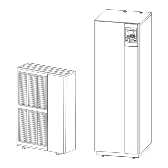
Air to Water Heat Pump
Split integrated DHW type
Outdoor unit
Hydraulic unit
WO*G112LCT
WG*G140DD6
WO*G140LCT
WG*K160DD9
WO*K112LCT
WO*K140LCT
WO*K160LCT
Installation and
operating manual
intended for professionals
To be saved for
future consultation
Fujitsu General
(Euro) GmbH
Werftstrasse 20
40549 Düsseldorf - Germany
Subject to modifications without notice.
Non contractual document.
Advertisement
Table of Contents

Related Manuals for Waterstage WO*G112LCT


Summary of Contents for Waterstage WO*G112LCT
-
Page 1: Outdoor Unit
Document n° 1586-1 ~ 20/02/2013 Air to Water Heat Pump Split integrated DHW type Outdoor unit Hydraulic unit WO*G112LCT WG*G140DD6 WO*G140LCT WG*K160DD9 WO*K112LCT WO*K140LCT WO*K160LCT Installation and operating manual intended for professionals To be saved for future consultation Fujitsu General... -
Page 2: Table Of Contents
Air to Water Heat Pump (Split integrated DHW type) " This device requires for its installation, the intervention of qualified personnel with a certificate of capacity for handling refrigerants . Contents Description of the unit . . . . . . . . . . . . . . . . . . . . . . . . . . . . . . 4 Package Description Definitions... - Page 3 Air to Water Heat Pump (Split integrated DHW type) Regulation system . . . . . . . . . . . . . . . . . . . . . . . . . . . . . . . 36 User interface, Remote control (option) and Parametering the setting Room thermostat (option)
-
Page 4: Description Of The Unit
Packing list Heat pump (HP) Outdoor unit Hydraulic unit Model Model Model Waterstage High Power Integrated DHW 11 Single phase WO*G112LCT WG*G140DD6 Waterstage High Power Integrated DHW 14 Single phase WO*G140LCT Waterstage High Power Integrated DHW 11 3-Phase WO*K112LCT Waterstage High Power Integrated DHW 14 3-Phase... -
Page 5: Specifications
Air to Water Heat Pump (Split integrated DHW type) 1 .3 Specifications Designation model Waterstage High Power Single phase Single phase 3-phase 3-phase 3-phase Nominal heating performances (outdoor temperature / initial temperature) Heat output +7 °C / +35 °C - Floor heating system... -
Page 6: Outside Unit
Air to Water Heat Pump (Split integrated DHW type) " Outside unit, Model High Power 11 & 14 single phase Overflow hole (Ø 20) Holes Ø 10) Sight of lower part 1290 3/8” 5/8” Front view Side view Top view "... - Page 7 Air to Water Heat Pump (Split integrated DHW type) " Hydraulic unit Heating return flow Heating Back view Side view Front view Blockage in the hydraulic unit, see figure 13, page 15 figure 2 - Dimensions in mm Installation and operating manual "1586 - EN" - 7 -...
- Page 8 Air to Water Heat Pump (Split integrated DHW type) Outdoor sensor QAC34 Variable pressure 1 mbar = 10 mmCE = 100 Pa mbar 43907 ext. in 10000 2490 1000 ° C m /h Heat pump return sensor Heat pump flow sensor Constante pressure 32500 1 mbar = 10 mmCE = 100 Pa...
-
Page 9: Description
Air to Water Heat Pump (Split integrated DHW type) 1 .4 Description " Model High Power " Model High Power 11 & 14 single phase 11, 14 & 16 3-phase WO*K1**LCT Legend : 1 - Low-noise, high-output fan. 2 - Electric variable speed "inverter" motor. 3 - "Inverter"... -
Page 10: Operating Principle
Air to Water Heat Pump (Split integrated DHW type) Legend : 1 - Electric box. 2 - Regulator / User interface. 3 - Start/stop switch. 4 - Hydraulic pumping unit. 5 - Distribution valve. 6 - Gas refrigeration connection. 7 - Liquid refrigeration connection. 8 - Condensation sensor. - Page 11 Air to Water Heat Pump (Split integrated DHW type) • Domestic hot water (DHW) operating principle Two domestic hot water (DHW) temperatures can be If the contract concluded with the energy provider parametered: nominal temperature (line 1610 to 55 °C) includes a subscription to day/night tariff, the electrical and reduced temperature (line 1612 to 40 °C).
-
Page 12: Installation
Air to Water Heat Pump (Split integrated DHW type) 2 Installation 2 .1 Regulation installation 2 .2 .3 Containment of refrigerant circuits and maintenance conditions All refrigerant circuits fear contamination from dust and moisture. If such pollutants introduced into refrigeration The appliance must be installed and the maintained by an circuit, they can contribute to degrade the reliability of approved professional in accordance with the prevailing... -
Page 13: Installation Position
Air to Water Heat Pump (Split integrated DHW type) 2 .3 Installation position 2 .4 Installation of the outdoor unit The choice of the position for installation is particularly 2 .4 .1 Installation precautions important insofar as any later movement is a delicate The outdoor unit must only be installed outdoor operation requiring the intervention of a qualified person. -
Page 14: Outdoor Unit Positioning
Air to Water Heat Pump (Split integrated DHW type) • Water may drain away from the outdoor unit when it is operating. Do not install the appliance on a paved terrace; choose a well-drained place (e.g. gravel or sand). If the installation is in an area where the temperature can be lower than 0°C for a long period, check that the presence of ice does not present any danger. -
Page 15: Installing The Hydraulic Unit
Air to Water Heat Pump (Split integrated DHW type) 2 .5 Installing the hydraulic unit 2 .5 .1 Installation precautions • The room in which the appliance operates must 300 mm comply with the prevailing regulations. • To facilitate maintenance and to allow access to the various components, we recommend that you provide sufficient space all around the hydraulic unit (figure... -
Page 16: Refrigeration Connections
Air to Water Heat Pump (Split integrated DHW type) 2 .6 Refrigeration connections " This appliance uses refrigerant R410A . Comply with the legislation for handling refrigerants. 2 .6 .1 Rules and precautions • After every intervention on the refrigeration circuit and before final connection, take care to replace the plugs in order to avoid any pollution from the refrigeration circuit. -
Page 17: Refrigeration Connections
Air to Water Heat Pump (Split integrated DHW type) • Flared connections 2 .6 .2 Refrigeration connections " Lubrication with mineral oil (for R12, R22) The outdoor unit must be connected to the hydraulic is forbidden . unit only with new copper pipes and connections (refrigeration quality), insulated separately. - Page 18 Air to Water Heat Pump (Split integrated DHW type) 2 .6 .4 Shaping the refrigeration pipes " Take particular care positioning the tube opposite its connector so as not to risk damaging The refrigeration pipes must be shaped only on a the threads .
-
Page 19: Filling The Installation With Gas
Air to Water Heat Pump (Split integrated DHW type) Filling the installation with gas ANNEX 2 " This operation is reserved for installers familiar with the legislation for handling refrigerants. Method 3 empty " Creating a vacuum with a vacuum pump is essential (see ANNEX 1). -
Page 20: Sealing Test
Air to Water Heat Pump (Split integrated DHW type) • First seal test Refrigeration connecxion (Gas) Refrigeration connexion - Remove the protective plugs (B) from the charging hole (Schrader) in the "Gas" valve (large diameter). Plug (A) - Connect the high pressure hose to the Manifold 3-way valve - Connect the bottle of nitrogen to the Manifold (Use only dry nitrogen type U). -
Page 21: Additional Charge
Air to Water Heat Pump (Split integrated DHW type) 2.7.3 Additional charge 2.7.4 Pump down operation (Refrigerant collecting operation) outdoor unit 50 g of R410A Perform the following procedures to collect the per additional meter refrigerant. Length of 15 m 20 m max. -
Page 22: Hydraulic Connecting
Air to Water Heat Pump (Split integrated DHW type) 2 .8 Hydraulic connecting 2 .8 .1 General The connection must comply with good trade practice The use of glycol is not necessary. If you are using a according to local building regulations. glycol/water mix, provide for an annual check on the quantity of glycol. -
Page 23: Connecting To The Dhw Circuit
Air to Water Heat Pump (Split integrated DHW type) 2 .8 .2 Connecting to the DHW circuit Install dielectric fittings and DHW pipes on the tank (see figure 24). Insulate DHW pipes with included insulation. " Be sure to put the DHW sensor at the bottom of the thermowell DHW. -
Page 24: Rinsing Out The Installation
Air to Water Heat Pump (Split integrated DHW type) 2 .9 Thermal insulation 2 .8 .3 Rinsing out the installation Before connecting the hydraulic unit to the installation, Install the thermal insulation kit on the metal parts to rinse out the heating system correctly to eliminate avoid the inconvenient effects of condensation. -
Page 25: Heating Circulation Pump Speed Settings
Air to Water Heat Pump (Split integrated DHW type) 2 .10 Heating circulation pump speed settings 1 mbar = 10 mmCE = 100 Pa mbar Variable pressure ext. in The circulator varies the manometric height according to the flowrate. Recommended for a system equipped with radiators (particularly any system with thermostatic valves). -
Page 26: Electrical Connections
Air to Water Heat Pump (Split integrated DHW type) 2 .11 Electrical connections Flexible wires (B) Ensure that the general electrical power supply has been cut off before starting any repair work. H07RNF type (or superior quality) flexible wire can be used with certain precautions: 2 .11 .1 Characteristic of the electrical supply - Strip away around 10 mm from the end of the wire. -
Page 27: Overview Of All The Electrical Connections
Air to Water Heat Pump (Split integrated DHW type) 2 .11 .3 Overview of all the electrical connections The wiring diagram for the hydraulic unit is shown in detail on figure 50, page 56 Wireless remote control (option) Outdoor sensor Cable 2 x 0,75 mm²... -
Page 28: Electrical Connections On The Single Phase Outdoor Unit Side
Air to Water Heat Pump (Split integrated DHW type) 2 .11 .5 Electrical connections on the single phase outdoor unit side Access to the connection terminals: - Make the connections in accordance with the diagram - Remove the front panel. Remove the screws and the figure 32 and figure 41, page 33 front panel. -
Page 29: Electrical Connections On The 3- Phase Outdoor Unit Side
Air to Water Heat Pump (Split integrated DHW type) 2 .11 .6 Electrical connections - Use cable clamps to prevent the conductors from being disconnected accidentally. on the 3- phase outdoor unit side - Fill in the space where the cables enter the outdoor Access to the connection terminals. -
Page 30: Electrical Connections On The Hydraulic Unit Side
Air to Water Heat Pump (Split integrated DHW type) 2.11.7 Electrical connections on the hydraulic unit side Access to the connection terminals: • Interconnection between the outdoor unit and the hydraulic unit - Remove the front panel. Comply with the correspondence between the markings - Open the power control box. - Page 31 Air to Water Heat Pump (Split integrated DHW type) Power shedding or EJP (peak day removal) Tariffs, peak times/off-peak times, day / night Wireless remote External fault control** External component contact* (faults, load shedder, power meter) M B9 B2 M B1 3 2 1 Outdoor sensor * If the control device does not provide a potential-free contact,...
- Page 32 Air to Water Heat Pump (Split integrated DHW type) " Model single phase Electrical Back-up Terminal blocks + Relays Safety thermostat HP regulator 230 V Interface card Cable grommet (power) Cable grommet (sensors) Relay Terminal blocks + DHW Terminal blocks "...
- Page 33 Air to Water Heat Pump (Split integrated DHW type) " Model single phase Hydraulic unit Outdoor unit single phase 1 2 3 230 V Green / yellow Brown Blue Interconnection between the outdoor unit and External component the hydraulic unit contact * Back-Up Electricity DHW Electricity...
-
Page 34: Outdoor Sensor
Air to Water Heat Pump (Split integrated DHW type) 2 .12 Outdoor sensor 2 .14 Commissioning The outdoor sensor is required for the heat pump to - Close the installation's main circuit breaker. operate correctly. On first commissioning (or in winter), in order to Consult the fitting instructions on the packaging. -
Page 35: Configuring Room Thermostat (Wireless)
Air to Water Heat Pump (Split integrated DHW type) 2 .15 Configuring room thermostat (wireless) To configure the room thermostat and connect it to the appropriate heating zone: - Hold down the presence key for more than 3 seconds. - Hold down presence key;... -
Page 36: Regulation System
Air to Water Heat Pump (Split integrated DHW type) 3 Regulation system 3 .1 User interface, Remote control (option) and Room thermostat (option) User interface Auto Auto °C Remote control (option) Room thermostat (option) figure 42 - Installation and operating manual "1586 - EN" - 36 -... - Page 37 Air to Water Heat Pump (Split integrated DHW type) Ref. Function - Definitions Selecting of the DHW operating mode - On: Production of DHW according to the time program. (Domestic hot water) - Off: Preparing the domestic hot water for stopping with the anti-frost function active.
-
Page 38: Description Of The Display
Air to Water Heat Pump (Split integrated DHW type) 3 .2 Description of the display 3 .3 Temperature control The heat pump's operation is subject to the temperature control. The set temperature for the water in the heating circuit is adjusted according to the outdoor temperature. If there are thermostatic valves on the installation, these must be fully open or adjusted for higher than the normal set temperature. - Page 39 Air to Water Heat Pump (Split integrated DHW type) Heating curve slope 2,75 ° C 2,25 Classic temperature radiator 1,75 Boiler connexion application 1,25 Heat pump application only temperature radiator 0,75 Floor heating 0,25 system ° C External temperature °C figure 44 - Heating curve slope (line 720) Heating curve slope +4,5...
-
Page 40: Parametering The Setting
Air to Water Heat Pump (Split integrated DHW type) 3 .4 Parametering the setting 3 .4 .2 Setting parameters - Choose the desired level. 3 .4 .1 General - Scroll the menu list. Only the parameters accessible to levels: - Choose the desired menu. U –... - Page 41 Air to Water Heat Pump (Split integrated DHW type) Line Function Setting range Setting Basic or display increment setting Time program heating, circuit 1 Pre-selection (Day / Week) Mon-Sun, Mon-Fri, Sat-Sun, Mon-Sun Monday, Tuesday, … 6:00 1st phase On (start) 00:00...
- Page 42 Air to Water Heat Pump (Split integrated DHW type) Line Function Setting range Setting Basic or display increment setting Time program 5 / Cooling If the installation is fitted with the cooling kit (Only with the cooling kit option). Pre-selection (Day / Week) Mon-Sun, Mon-Fri, Sat-Sun, Mon-Sun Monday, Tuesday, …...
- Page 43 Air to Water Heat Pump (Split integrated DHW type) Line Function Setting range Setting Basic or display increment setting Room influence 1%... 100% If the installation is fitted with a room thermostat: This function enables you to choose the ambient temperature's influence on the setting. If no value is entered, the setting is made based on the temperature control.
- Page 44 Air to Water Heat Pump (Split integrated DHW type) Line Function Setting range Setting Basic or display increment setting Cooling circuit 1 If the installation is fitted with the cooling kit (Only with the cooling kit option). Operating mode Off, Automatic Comfort cooling setpoint 40 °C 0,5 °C...
- Page 45 Air to Water Heat Pump (Split integrated DHW type) Line Function Setting range Setting Basic or display increment setting 1041 Flow temp setpoint max 70 °C 1 °C 55 °C Floor heating system = 50 °C / Radiators = 65 °C. Important Note : Maximum temperature limitation is not a safety function as required by ground heating.
- Page 46 Air to Water Heat Pump (Split integrated DHW type) Line Function Setting range Setting Basic or display increment setting Domestic hot water 1610 Nominal setpoint Reduced setpoint (line 1612)… 55 °C 65 °C The backup electrical system is required to reach this level. 1612 Reduced setting 8 °C...
- Page 47 Air to Water Heat Pump (Split integrated DHW type) Line Function Setting range Setting Basic or display increment setting Additional generator (Boiler connection) 3692 With DHW charging Locked, Substitute, Substitute Complement, Instantly - DHW Instantly : When DHW request, the HP and the boiler are put into operation. The HP will stop when the primary return temperature is over 55 °C.
- Page 48 Air to Water Heat Pump (Split integrated DHW type) Line Function Setting range Setting Basic or display increment setting 6220 Software version (RVS) 6420 Function input H33 (= contact in X152) (1) Mode changeover HC+DHW - (2) Mode changeover HC - (3) Mode changeover HC1 - (4) Mode changeover HC2 - (5) Mode changeover HCP - (6) to (10) Not used - (11) Mode changeover Heating Swimming pool - (12) to (56) Not used.
- Page 49 Air to Water Heat Pump (Split integrated DHW type) Line Function Setting range Setting Basic or display increment setting 7710 Output UX1 test (3-phase electrical back-up command) 0... 100% 7712 PWM signal UX1 0... 100% 7716 Output UX2 test 0... 100% 7719 PWM signal UX2 0...
- Page 50 Air to Water Heat Pump (Split integrated DHW type) Line Function Setting range Setting Basic or display increment setting 8410 Return temp HP 140 °C Setpoint (flow) HP 8412 Flow temp HP 140 °C Setpoint (flow) HP 8413 Compressor modulation 0...
- Page 51 Air to Water Heat Pump (Split integrated DHW type) Line Function Setting range Setting Basic or display increment setting 8770 Room temperature 2 50 °C Room setpoint 2 20 °C 8773 Flow temperature 2 140 °C Flow temperature setpoint 2 8820 DHW pump Off, On...
-
Page 52: Overall Hydraulic Layout
Air to Water Heat Pump (Split integrated DHW type) 4 Overall hydraulic layout • Configuration 1: 1 heating circuit Installation and operating manual "1586 - EN" - 52 -... - Page 53 Air to Water Heat Pump (Split integrated DHW type) • Configuration 2: 2 heating circuits Installation and operating manual "1586 - EN" - 53 -...
-
Page 54: Electrical Wiring Diagrams
Air to Water Heat Pump (Split integrated DHW type) 5 Electrical wiring diagrams Option(connector) Printed Circuit Board Pressure Refer to the sensor (Disply) technical manual Thermistor (compressor) Thermistor (outdoor) Thermistor (pipe) Thermistor (discharge) Expansion Fuse valve coil Thermistor (heat sink) F4 T 5A - 250 V Thermistor (pipemid) - Page 55 Air to Water Heat Pump (Split integrated DHW type) Expansion valve coil (Inj) Solenoid coil (Inj) Thermistor Inj expansion Inverter PCB assy valve Thermistor heat exchanger mid Thermistor heatsink PFC Thermistor discharge pipe Thermistor heat exchanger out Compressor Thermistor Capacitor outdoor temp.
- Page 56 Air to Water Heat Pump (Split integrated DHW type) Start/stop switch Connection to terminal block (see figure 41, page figure 50 - Electrical wiring, Hydraulic unit High Power integrated DHW single phase (Except installer's connections) Installation and operating manual "1586 - EN" - 56 -...
- Page 57 Air to Water Heat Pump (Split integrated DHW type) Start/stop switch Connection to terminal block (see figure 41, page figure 51 - Electrical wiring, Hydraulic unit High Power integrated DHW 3-phase (Except installer's connections) Installation and operating manual "1586 - EN" - 57 -...
-
Page 58: Troubleshooting
Air to Water Heat Pump (Split integrated DHW type) 6 Troubleshooting Depending on whether the fault comes from the outdoor The display shows the symbol. unit or the hydraulic unit, the fault may be indicated by the digital display or the diode on the interface cards. Press the key for more details on the origin of the 6 .1... -
Page 59: Information Display
Air to Water Heat Pump (Split integrated DHW type) 6 .2 Information display Various data can be displayed by pressing the info - Various data (see below). button. Designation Line Depending on the type of unit, configuration and Floor drying current setpoint. operating state, some of the info lines listed below may not appear. -
Page 60: Faults Displayed On The Single Phase Outdoor Unit
Air to Water Heat Pump (Split integrated DHW type) 6 .3 Faults displayed on the single phase outdoor unit To access the electronic board, you must remove the front (right-hand) facing from the outdoor unit. Faults are coded by diode flashes. When an error occurs: - The diode "ERROR"... -
Page 61: Faults Displayed On The 3-Phase Outdoor Unit
Air to Water Heat Pump (Split integrated DHW type) 6 .4 Faults displayed on the 3-phase outdoor unit Diodes and switches To access the electronic board, you must remove the front (right-hand) facing from the outdoor unit. Faults are coded by diode flashes. When an error occurs: - The diode "ERROR"... -
Page 62: Maintenance Of The Installation
Air to Water Heat Pump (Split integrated DHW type) 7 Maintenance of the installation Ensure that the general electrical power supply has been cut off before starting any repair work. Hydraulic checks " Warning : If frequent refills are required it is essential that you look for any leaks . -
Page 63: Maintenance
Air to Water Heat Pump (Split integrated DHW type) 8 Maintenance 8 .1 Emptying the hydraulic unit - Remove the facade from the hydraulic unit. - Place the distribution valve in the middle position. Heating - Open the emptying valve (ref. 5). return - Open the hydraulic unit’s manual bleed-tap (ref. -
Page 64: Quick-Start Procedure
Air to Water Heat Pump (Split integrated DHW type) 10 Quick-start procedure Before switching on the hydraulic unit: • Check the electric wiring. • Check the refrigeration circuit and make sure the gas supply has been performed. • Check the pressure of the hydraulic circuit (1-2 bar), check that the heat pump is purged, and the rest of the installation. -
Page 65: Starting-Up
Air to Water Heat Pump (Split integrated DHW type) 10 .1 .2 Starting-up • Switching On (see chapiter "Star-up" page 28 Non compliant & chapiter "List of function lines (settings, diagnosis, status)", page 40). Engage the installation's main circuit breaker (power supply to the outdoor unit) 2 hours before starting up the tests =>... -
Page 66: Settings Sheet
Air to Water Heat Pump (Split integrated DHW type) 10 .2 Settings sheet Setting Description Set to. Menus Setting Description Set to. Menus Preliminary settings Boiler backup language 3700 OT.switch-on authoris. operator addit. gen. section 3705 swith-off delay addit. gen. hour / minutes time &... -
Page 67: Start-Up Data Sheet
Air to Water Heat Pump (Split integrated DHW type) 10 .3 Start-up data sheet Site Installer serial No. serial No. Outdoor unit Hydraulic unit model model Refrigerant type Refrigerant charge Checks Operating voltage & current on outdoor unit Compliance with positioning distances L/N or L1/N Condensate evacuation correct L2/N... - Page 68 Complies with : - Low voltage directive 2006/95/EC, under standard EN 60335-1. - Electromagnetic compatibility Diretive 2004/108/EC, - Directive 2006/42/EC Machinery, - Directive for pressurised equipment 97/23/EC. This appliance also conforms to: - Regulation 842/2006 of the european parliament on certain fluorinated greenhouse gases. - The standards relating to the product and the testing methods used: Air-conditioners, refrigeration units and heat pumps with compressor driven by electric motor for heating and refrigeration EN 14511-1, 14511-2, 14511-3, and 14511-4.
Need help?
Do you have a question about the WO*G112LCT and is the answer not in the manual?
Questions and answers