Table of Contents
Advertisement
Air to Water Heat Pump
Split system (3 phase type)
Outdoor unit
WO*K112LCT
WO*K140LCT
WO*K160LCT
Hydraulic unit
WS*K160DA9
Document n° 1364-9 ~ 06/02/2013
FR
EN
IT
NL
ES
PT
PL
LT
Installation and
operating manual
intended for professionals
To be saved for
future consultation
Fujitsu General
(Euro) GmbH
Werftstrasse 20
40549 Düsseldorf - Germany
Subject to modifications without notice.
Non contractual document.
DE
CZ
Advertisement
Table of Contents

Related Manuals for Waterstage WS*K160DA9


Summary of Contents for Waterstage WS*K160DA9
- Page 1 Document n° 1364-9 ~ 06/02/2013 Air to Water Heat Pump Split system (3 phase type) Outdoor unit Hydraulic unit WO*K112LCT WS*K160DA9 WO*K140LCT WO*K160LCT Installation and operating manual intended for professionals To be saved for future consultation Fujitsu General (Euro) GmbH Werftstrasse 20 40549 Düsseldorf - Germany...
-
Page 2: Table Of Contents
Split system (3-phase) " This device requires for its installation, the intervention of qualified personnel with a certificate of capacity for handling refrigerants Contents Description of the unit Package Heating power curve Definitions Description Specifications Operating principle Installation Regulation installation and maintenance conditions Connecting the heating circuit hydraulically Unpacking and reservations General... - Page 3 Split system (3-phase) Regulation system User interface and room control unit (option) Parametering the setting Room thermostat (option) General Temperature control Setting parameters Manual adjustment List of function lines (settings, diagnosis, status) Self-adaptation Configuring the installation Configuration 1, 2, 3 or 4: heat pumps with electric back-ups Parametering the setting Hydraulic connections...
- Page 4 Split system (3-phase) Packing list Heat pump Outdoor unit Hydraulic module WO*K112LCT WO*K140LCT WS*K160DA9 WO*K160LCT Optional equipment Scope of application This heat pump provides : • 2nd circuit kit (UTW-KZS*A). - for connecting 2 heating circuits. - Heating in winter.
-
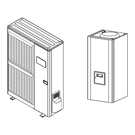
Page 5: Description Of The Unit
Split system (3-phase) 1 Description of the unit Definitions Package Split : The heat pump consists of two elements • 1 package : Outdoor unit. (an outdoor unit for outside and a hydraulic unit for • 1 package : Hydraulic unit and outdoor sensor. inside the dwelling). -
Page 6: Specifications
Split system (3-phase) Specifications Designation, model . . . . . . . . . . . . . . . . . . . . . . . . . . . . . . . . . . . . . . . . . . . 112 . . . . . . . . . . 140 . . . . . . . . . . .160 Designation, model . - Page 7 Split system (3-phase) " Outdoor unit Overflow hole (ø 20) 4 holes (ø 10) Bottom view 1290 Front view Side view Top view Figure 2 - Dimensions in mm " Hydraulic unit 1000 1034 Heating return Heating flow ø M 26x34 ø...
-
Page 8: Installation
Split system (3-phase) Outdoor sensor QAC34 1mbar = 10 mmCE = 100 Pa mbar 43907 10000 2490 1000 ° C Figure 4 - Hydraulic pressures and flow rates available Heat pump return sensor Heat pump flow sensor 10000 32500 - Compressor casing 30000 - Discharge - Condensation... -
Page 9: Heating Power Curve
Split system (3-phase) Heating power curve Values according to standard EN 14511, for which it is necessary to add the power absorbed by the heating circulation pump . Floor heating system (35°C) Low temperature radiator (45°C) Classic radiator (60°C) Heat output Power absorbed Outside temperature (°C) Floor heating system (35°C) -
Page 10: Description
Split system (3-phase) Description WO*K1**LCT Legend : 1 - Low-noise, high-output propeller fan. 2 - Electric variable speed "inverter" motor. 3 - "Inverter" control module. 4 - Control lights and buttons. 5 - Connection terminal blocks (power and interconnection). 6 - Refrigerant accumulator bottle. 7 - Four way valve. -
Page 11: Operating Principle
Split system (3-phase) Operating principle • Domestic hot water (DHW) operating principle The heat pump transmits the energy contained in the surrounding air into the dwelling to be heated. Two domestic hot water (DHW) temperatures can be parametered: comfort temperature (line 1610 to 50 °C) The heat pump consists of four main elements, in which and reduced temperature (line 1612 to 25 °C). -
Page 12: Installation
Split system (3-phase) 2 Installation Regulation installation 2 2 3 Containment of refrigerant circuits and maintenance conditions All refrigerant circuits fear contamination from dust and The appliance must be installed and the maintained moisture. If such pollutants introduced into refrigeration by an approved professional in accordance with the circuit, they can contribute to degrade the reliability of prevailing regulations and code of practice, in particular:... -
Page 13: Installation Of The Outdoor Unit
Split system (3-phase) Installation of the outdoor unit exposed to significant dirt or flowing water (under a defective gutter for example). 2 4 1 Installation precautions • Water may drain away from the outdoor unit when it is operating. Do not install the appliance on a paved "... -
Page 14: Outdoor Unit Positioning
Split system (3-phase) temperature of the air being blown out, with the risk of freezing plants in its path). • The surface supporting the outdoor unit should: - be permeable (soil, gravel, etc), - support its weight easily, - provide a solid fixing and - not transmit vibration... -
Page 15: Installing The Hydraulic Unit
Split system (3-phase) Installing the hydraulic unit - If the refrigerant connection only occurs at the end of the installation, be sure that the refrigerant circuit caps* 2 5 1 Installation precautions remain in place and tight throughout the installation duration. -
Page 16: Refrigeration Connections
Split system (3-phase) Refrigeration connections • To eliminate any filings in the pipes, use dry nitrogen " This appliance uses refrigerant R410A to avoid introducing any humidity that may adversely Comply with the legislation for handling refrigerants. affect the appliances operation. In general, take every precaution to avoid humidity penetrating into the 2 6 1 Rules and precautions appliance. -
Page 17: Creating The Flarings
Split system (3-phase) 2 6 3 Creating the flarings 2 6 4 Shaping the refrigeration pipes - Cut the pipe to an appropriate length with a pipe-cutter The refrigeration pipes must be shaped only on a without deforming it. bending machine or with a bending spring in order to avoid any risk of crushing or breaking them. - Page 18 Split system (3-phase) Diameter of refrigeration Outdoor unit connections Hydraulic unit connections connections 5/8" (D1) 5/8" 5/8" Liquid 3/8" (D2) 3/8" 3/8" Liquid valve Gas valve Flare nut Liquid refrigeration connection diameter D2 Flare nut Flare nut Flare nut Gas refrigeration connection diameter D1 Figure 20 - Connecting the flared connections - 18 -...
-
Page 19: Filling The Installation With Gas
Split system (3-phase) Filling the installation with gas ANNEX 2 " This operation is reserved for installers familiar with the legislation for handling refrigerants. Method 3 empty " Creating a vacuum with a vacuum pump is essential (see ANNEX 1). - Connect the high pressure hose to the Manifold, ("Gas"... -
Page 20: Sealing Test
Split system (3-phase) • First seal test - Remove the protective plugs (B) from the charging High pressure hose (red) Plug (B) hole (Schrader) in the "Gas" valve (large diameter). - Connect the high pressure hose to the Manifold (figure 21). - Connect the bottle of nitrogen to the Manifold Plug (A) Load orifice... -
Page 21: Additional Charge
Split system (3-phase) 2 7 3 Additional charge 50 g of R410A per additional meter Length of the connections 15 m 20 m ( maxi.) Additional charge none 250 g 2 7 4 Pump down The charge in the outdoor units corresponds to the (Refrigerant collecting operation) maximum distances between the outdoor unit and the hydraulic unit defined in... -
Page 22: Connecting The Heating Circuit Hydraulically
Split system (3-phase) Connecting 2 8 2 Rinsing out the installation the heating circuit hydraulically Before connecting the hydraulic unit to the installation, rinse out the heating system correctly to eliminate 2 8 1 General any particles that may affect the appliance’s correct The connection must comply with good trade practice operation. - Page 23 Split system (3-phase) Installation and operating manual "1364 - EN" - 23 -...
-
Page 24: Electrical Connections
Split system (3-phase) Electrical connections • Connecting to screw terminals Rigid wires (A, figure 27). Ensure that the general electrical power supply has Rigid wires are always preferable for fixed installations, been cut off before starting any repair work. particularly in a building. 2 9 1 Characteristic of the electrical supply - Always select a wire that complies with the prevailing The electrical installation must be conducted in... -
Page 25: Overview Of All The Electrical Connections
Power supply to the electrical back-ups Cable connection Power Nominal intensity Curve C circuit breaker size (3 Phase, Earth) WS*K160DA9 9 kW 13 A 4 x 2,5 mm² 20 A • Outdoor sensor, room thermostat and room control unit For the outdoor sensor, use a 2 x 0,75 mm² cable. -
Page 26: On The Outdoor Unit Side
Split system (3-phase) 2 9 5 Electrical connections - Use cable clamps to prevent the conductors from being disconnected accidentally. on the outdoor unit side - Fill in the space where the cables enter the outdoor Access to the connection terminals. unit with the insulating plate. -
Page 27: On The Hydraulic Unit Side
Split system (3-phase) 2 9 6 Electrical connections on the hydraulic unit side Access to the connection terminals. Do not place the sensor lines and the sector supply lines in parallel in order to avoid causing inadvertent - Remove the front panel (2 screws) interference due to voltage points in the sector supply. - Page 28 Split system (3-phase) Outdoor unit Hydraulic unit 1 2 3 4 5 6 7 8 20 21 22 23 12 13 14 15 16 17 18 19 RP DHW 1 2 3 L1 L2 L3 N N COM OUTDOOR SECOND ELECTRIC BOILER BOILER...
-
Page 29: Outdoor Sensor
Split system (3-phase) Outdoor sensor Room thermostat circuit 1 Room thermostat circuit 2 External fault Tariffs, day / night, peak times/off-peak times Power shedding Room control unit or EJP (peak day removal) External component contact* (faults, load shedder, power meter) * If the control device does not provide a potential-free contact, the contact must be relayed to create equivalent wiring. -
Page 30: Start-Up
Split system (3-phase) 2 12 Start-up 2 13 Configuring the room thermostat - Make sure that ALL DIP SW are OFF before starting To configure the room thermostat and connect it to the up. DIP SW shuold be set OFF for normal operation. appropriate heating zone : Power supply to the hydraulic unit must be turned off - Hold down the presence key for more than 3 seconds. -
Page 31: User Interface And Room Control Unit (Option)
Split system (3-phase) 3 Regulation system User interface and room control unit (option) Auto Auto Figure 39 - RESET Ref. Function - Definitions Selecting of the DHW operating mode - If the installation is fitted with a DHW tank. (Domestic hot water). - On : Production of DHW according to the time program. -
Page 32: Room Thermostat (Option)
Split system (3-phase) Room thermostat (option) Auto °C Figure 40 - Room thermostat (option) Ref. Function - Definitions Selecting the heating mode. Auto Heating operating according to the heating programme (Summer/winter mode switchover is automatic). Constant comfort temperature. Constant reduced temperature. Stand-by mode with anti-frost protection (Provided that the heat pump's electrical power supply is not interrupted). - Page 33 Split system (3-phase) Heating curve slope 2,75 ° C 2,25 Classic temperature radiator 1,75 Boiler connection application 1,25 Heat pump application only temperature radiator 0,75 Floor heating system 0,25 ° C Outdoor temperature °C Figure 41 - Heating curve slope (line 720) Heating curve slope +4,5 -4,5...
-
Page 34: Parametering The Setting
Split system (3-phase) Parametering the setting 3 4 2 Setting parameters - Choose the desired level. 3 4 1 General - Scroll the menu list. Only the parameters accessible to levels : - Choose the desired menu. U - End user. - Scroll the function lines. - Page 35 Split system (3-phase) Setting range Setting Basic Line Function or display increment setting Operation HCP (domestic hot water pump command, output QX2) Commonly with Commonly with HC1 or Independent (if independent, see timer program 3 / HCP) Software version (Display) Heating time programme, circuit 1 Mon-Sun Pre-selection (Day / Week)
- Page 36 Split system (3-phase) Setting range Setting Basic Line Function or display increment setting Time programme 5 / Cooling If the installation is fitted with the cooling kit (Only with the cooling kit option). Pre-selection (Day / Week) Mon-Sun Mon-Fri Sat-Sun Mon-Sun Monday Tuesday…...
- Page 37 Split system (3-phase) Setting range Setting Basic Line Function or display increment setting 55 °C Flow temp setpoint max 8... 95 °C 1 °C Floor heating system = 50 °C / Higher temperature radiator = 65 °C Room influence 1%... 100% If the installation is fitted with a room thermostat : This function enables you to choose the ambient temperature's influence on the setting.
- Page 38 Split system (3-phase) Setting range Setting Basic Line Function or display increment setting Cooling circuit 1 Operating mode Off, Automatic Comfort cooling setpoint 17... 40 °C 0,5 °C 24 °C Time Release 24h/day, Time program HC, Time program 5 / Refresh program 5 If the installation is fitted with a DHW tank, set the parameter 907 to "...
- Page 39 Split system (3-phase) Setting range Setting Basic Line Function or display increment setting 18 °C 1030 Summer / Winter heating limits 8... 30 °C 0,5 °C When the average of the outdoor temperatures over the past 24 hours reaches 18°C, the regulator switches off the heating (as an economy measure).
- Page 40 Split system (3-phase) Setting range Setting Basic Line Function or display increment setting 1620 Release (of DHW load) 24h / day Time program Time programs HCs 4/DHW Time program 4/DHW Low-tariff T'prog 4/DHW or low-tariff 24h / day : The temperature of the DHW is constantly maintained at the DHW comfort setting. Time programs HCs : The DHW is produced according to the programming for the ambient temperature (with 1 hour in advance when switched on).
- Page 41 Split system (3-phase) Setting range Setting Basic Line Function or display increment setting Additional generator (Boiler connection) 3700 Release under outdoor temperature --, -50... 50 °C 0,5 °C 2 °C 3705 Overrun time 0... 120 min 1 min 20 min 3720 Switching integral (for boiler relief) 0...
- Page 42 Split system (3-phase) Setting range Setting Basic Line Function or display increment setting Error 6711 Reset HP No, Yes 6740 Flow temp HC1 alarm --, 10... 240 min 10 min 6741 Flow temp HC2 alarm --, 10... 240 min 10 min 6745 DHW charging alarm --, 1...
- Page 43 Split system (3-phase) Setting range Setting Basic Line Function or display increment setting Inputs / outputs test 7700 Relay test No test This consists of instructing the regulator's relays one by one and checking their outputs. This enables you to check that the relays are working and that the cabling is correct.
- Page 44 Split system (3-phase) Setting range Setting Basic Line Function or display increment setting 8060 History 6 Time, Date, State code 8062 History 7 Time, Date, State code 8064 History 8 Time, Date, State code 8066 History 9 Time, Date, State code 8068 History 10 Time, Date, State code...
- Page 45 Split system (3-phase) Setting range Setting Basic Line Function or display increment setting 8760 Heating circuit pump, circuit 2 Off, On 8761 Mixer valve HC2 open Off, On 8762 Mixer valve HC2 closed Off, On 8770 Room temperature 2 0... 50 °C 20 °C 20 °C Room setpoint 2...
-
Page 46: Configuring The Installation
Split system (3-phase) 4 Configuring the installation " Optional DHW kit " Optional boiler connection kit DHW tank control (with electrical back-up) requires the The connection of an oil or gas boiler to the heat pump use of the DHW kit. requires the installation of the boiler connection kit. -
Page 47: Heat Pumps With Electric Back-Ups
Split system (3-phase) Configuration 1, 2, 3 or 4: heat pumps with electric back-ups " Parameter 5700 Configuration 1 : 1 heating circuit (see figure page 45). Configuration 2 : 1 heating circuit and DHW tank. (see figure page 46). Configuration 3 : 2 heating circuits (see figure page 47). - Page 48 Split system (3-phase) Configuration 1 : " See detailed instructions 1 heating circuit page 44 Overall hydraulic layout Overview of all the electrical connections Legend CC - Heating circulation pump. R - Radiators (or fan convectors). SA - Room thermostat (option). SE - Outdoor sensor.
- Page 49 Split system (3-phase) Configuration 2 : " See detailed instructions 1 heating circuit and DHW tank page 44 Overall hydraulic layout Overview of all the electrical connections Legend CAR - Non-return valve. SA - Room thermostat (option). AE - Electric back-up. SE - Outdoor sensor.
- Page 50 Split system (3-phase) Configuration 3 : " See detailed instructions 2 heating circuits page 44 Overall hydraulic layout SDp1 Overview of all the electrical connections SDp1 Legend K2c - 2 SE - Outdoor sensor. circuit kit. CAR - Non-return valve. R - Radiators (or fan convectors).
- Page 51 Split system (3-phase) Configuration 4 : " See detailed instructions 2 heating circuits and DHW tank page 44 Overall hydraulic layout SDp1 Overview of all the electrical connections SDp1 Legend SE - Outdoor sensor. KS - DHW kit. SDp1 - Flow sensor, Circuit 1. AE - Electric back-up.
-
Page 52: Electrical Wiring Diagrams
Split system (3-phase) 5 Electrical wiring diagrams Expansion valve coil (Inj) Solenoid coil (Inj) Thermistor Inj expansion Inverter PCB assy valve Thermistor heat exchanger mid Thermistor heatsink PFC Thermistor discharge pipe Thermistor heat exchanger out Compressor Thermistor Capacitor outdoor temp . Thermistor PCB assy (Heatsink inv .) - Page 53 Split system (3-phase) CN30 LED 2 LED 1 Timed fuse CN18 3,15 A - 250V Condensation CN16 CN22 sensor Connections to the heat pump regulator (accessories and options) (see figure 38, page Return sensor REL2 Flow sensor REL1 Heating Uref circulation pump X-30...
-
Page 54: Information Display
Split system (3-phase) 6 Troubleshooting Depending on whether the fault comes from the outdoor unit or the hydraulic unit, the fault may be indicated by the digital display or the diode on the interface cards. Designation Line Information display Floor drying current setpoint . Various data can be displayed by pressing the info Current drying day. -
Page 55: Faults Displayed On Hydraulic Unit
Split system (3-phase) Faults displayed on hydraulic unit Faults or breakdowns on the hydraulic mode are The display shows the “Bell” symbol indicated by the display on the user interface. Press the Info key for more details on the origin of the fault. -
Page 56: Faults Displayed On The Outdoor Unit
Split system (3-phase) Faults displayed on the outdoor unit When an error occurs : To access the electronic board, you must remove the front (right-hand) facing from the outdoor unit. - The diode "ERROR" (2) blinks. Faults are coded by diode flashes. •... -
Page 57: Start-Up Check-List
Split system (3-phase) 7 Quick-start procedure Before switching on the hydraulic unit : • Check the electric wiring. • Check the refrigeration circuit and make sure the gas supply has been performed. • Check the pressure of the hydraulic circuit (1-2 bar), check that the heat pump is purged, and the rest of the installation. -
Page 58: Start-Up
Split system (3-phase) Start-up - Turn ON the start/stop switch. - Time, Date and time programs for HC1, HC2, DHW if different than default values (settings 500 – 576). - Configure the hydraulic circuit (setting 5700) : - Ajust the heating curve slope (720; 1020) and curve Presettings : off-set (721;... -
Page 59: Settings Sheet
Split system (3-phase) Settings sheet Setting Description Set to . Menus Setting Description Set to . Menus Boiler backup Preliminary settings 3700 OT.switch-on authoris. addit . gen . language operator section 3705 swith-off delay addit . gen . hour / minutes time &... -
Page 60: Start-Up Data Sheet
Split system (3-phase) Start-up data sheet Site Installer serial No. serial No. Outdoor unit Hydraulic unit model model Refrigerant type Refrigerant charge Checks Operating voltage & current on outdoor unit Compliance with positioning distances L1/N Condensate evacuation correct L2/N Electric connections / connections tightnees L3/N No GAS leaks (unit ID No . -
Page 61: Instructions For The User
Split system (3-phase) 8 Instructions for the user Explain to the user how his installation operates, in Emphasise that a heated floor has significant inertia particular the functions of the room thermostat and the and that therefore any adjustments must be made programmes accessible to him from the user interface. - Page 62 Split system (3-phase) - 62 - Installation and operating manual "1364 - EN"...
- Page 63 Split system (3-phase) Installation and operating manual "1364 - EN" - 63 -...
- Page 64 Complies with : - Low voltage directive 2006/95/EC, under standard EN 60335-1. - Electromagnetic compatibility Diretive 2004/108/EC, - Directive 2006/42/EC Machinery, - Directive for pressurised equipment 97/23/EC. This appliance also conforms to: - Regulation 842/2006 of the european parliament on certain fluorinated greenhouse gases - The standards relating to the product and the testing methods used: Air-conditioners, refrigeration units and heat pumps with compressor driven by electric motor for heating and refrigeration EN 14511-1, 14511-2, 14511-3, and 14511-4 - To standard XP ENV 12102: Air-conditioners, heat pumps and dehumidifiers with compressor driven by electric motor.
Need help?
Do you have a question about the WS*K160DA9 and is the answer not in the manual?
Questions and answers