
Related Manuals for GLP Impression 120RZ RGB

Summary of Contents for GLP Impression 120RZ RGB
- Page 1 1.24/30 (Instruction version 1.5) e-mail: service@glp.de Internet: http://www.glp.de...
- Page 2 Notes: German Light Products GmbH (Instruction version 1.5) / from software version 1.24/30)
-
Page 3: Table Of Contents
Table of contents Description of Device....................4 1.1 Safety Instructions .................... 5 Preparation and Installation ................... 6 2.1 Mounting ......................6 2.1.1 Mounting on the floor (upright) ............. 7 2.1.2 Mounting in hanging position (head down) .......... 8 2.1.3 Mounting in a sideway position ............8 2.2 Securing the Device .................. -
Page 4: Description Of Device
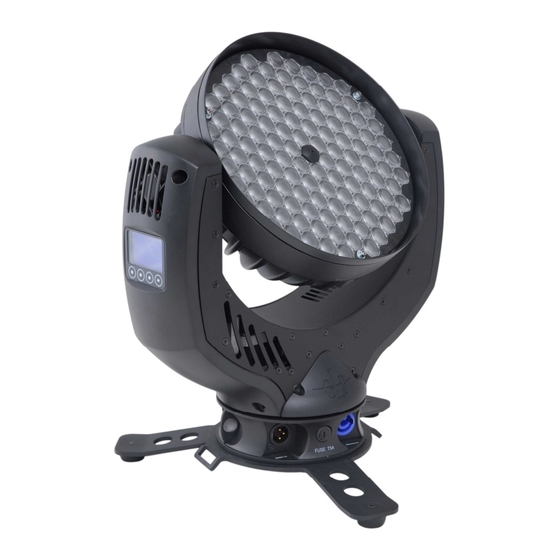
1 Description of Device 1. Moving head (actively and passively cooled) 2. Arm with various cooling vents 3. LCD-Display/Menu (data entry) 4. Base with various connectors and Camlock mounting system b a se sid e 1 5. Power On/Off 6. DMX- Output (3 pole) 7. -
Page 5: Safety Instructions
Safety Instructions N is an advanced technology product. To guarantee smooth operation, it is necessary to follow the following instructions. The manufacturer of this device will not take responsibility of damages through any disregard of the information in this user manual. -
Page 6: Preparation And Installation
10. Repair-, maintenance- and installation work should only be performed by qualified or GLP certified staff. You need to pay attention to the common rules of technology that are not explicit mentioned in this manual. 11. Use only original spare parts. Any structural modification on the system will terminate all warranty claims. -
Page 7: Mounting On The Floor (Upright)
For the various mounting positions of the N (standing on the floor, sideways or hanging) different accessories kits are available. Using any required kits, along with the standard mounting connectors on the base of the fixture, will ensure a safe and firm installation. 1x M10 (length max.16mm) 2x Camlock... -
Page 8: Mounting In Hanging Position (Head Down)
To operate the N in a sideways position, please use an additional mounting bar, available from GLP or one of their agents.. This mounting bar is fixed via the two camlock quick-release connectors. Two half-couplers or clamps are then used to hang the mounting bar. This technique is necessary to cope with the additional torque in this mounting position. -
Page 9: Securing The Device
2x 90° Half-coupler (clamp) 1 Half-coupler (clamp) 2 without mounting bar 2.2 Securing the Device Regardless of the mounting method of the N you'll have to use a secondary safety wire. This safety wire can be attached to the fixture by threading it through one of the two holes provided on the base of the fixture. -
Page 10: Dmx
2.3.2 DMX USITT DMX-512 Standard input/output with 3 pole connectors. 3 pole: Pin 1 = [Ground] / Pin 2 = [-] / Pin 3 = [+] The DMX- Addressing starts at DMX- Address [001]. 3 The Menu Field You’ll find the control board on the side of the arm. It allows you to make all necessary adjustments of the . - Page 11 Resetting all functions to original values (Full Full Feature Feature) Set Dimmer Changes PWM frequency between 600Hz and Frequency 1200Hz LED Dimmer Reads out the current LED dimmer (software) version Version Impression Reads out the current CPU software version Version Key code Use the code to enter the calibration menu (for Adjust...
- Page 12 Speed Instantaneous value for speed movements Movements Pan/Tilt Instantaneous value for pan/tilt movements Movements Special Instantaneous value for special channel White Instantaneous value for white temperature Temperature Dimmer Instantaneous value for dimmer Shutter Instantaneous value for shutter Blue Instantaneous value for blue Green Instantaneous value for green Instantaneous value for red...
-
Page 13: Dmx Channel Selection (Dmx Protocol)
Default Set “Full Feature” This mode resets the Theater Mode This mode runs the fans of the fixture slower, reducing noise.. If the temperature of the becomes too hot the fans do not increase in speed. Instead, the LED´s will dim down from their output level to reduce the heat. - Page 14 Channel Function Time and Value Up-dimming then Shutter closing slow - fast 48..79 30..4F 19..31 (random patterns) Shutter open then down-dimming slow - fast 80..111 50..6F 32..43 (random patterns) Up-dimming then down-dimming slow - fast 112..143 70..8F 44..56 (random patterns) Strobe effect pause 5s ..
- Page 15 Channel Function Time and Value Circle (inverse) size / phase see also PAN 160..191 A0..BF 63..75 Lying eight size / phase see also PAN 192..223 C0..DF 76..87 Random movement size see also PAN 224..255 E0..FF 88..100 14) Speed Pan/Tilt relative movement 0..1 00..01 0..0,5...
- Page 16 Compress-Mode 11 DMX channels Channel Function Time and Value 1) PAN- 0 .. 660° 3,2 s 0..255 00..FF 0..100 coarse 2) PAN-fine High- Pos ... High- Pos + 2,6° (16 Bit) 0..255 00. .FF 0..100 3) Tilt- 0 .. 300° 1,5 s 0..255 00..FF...
- Page 17 High Resolution (Extended) -Mode 14 DMX Channels Channel Function Time and Value 1) PAN- 0 .. 660° 3,2 s 0..255 00..FF 0..100 coarse 2) PAN-fine High- Pos ... High- Pos + 2,6° (16 Bit) 0..255 00. .FF 0..100 3) Tilt- 0 ..
-
Page 18: Maintaining And Cleaning The I M P R E S S I O N
Locking and unlocking the Control Panel You can lock and unlock the control panel by pressing the menu keys MODE & ENTER & UP at the same time. Additional shortcut features when switching on the fixture a) 1200Hz Mode (Hold down the UP- button during power ON) After switching on, the fixture the LEDs will be operated with a Pulse Width Modulation (PWM) of 1200Hz. -
Page 19: Safety Regulations
5.1 Safety regulations • Disconnect the fixture from the mains power before commencing any maintenance work! • Wait minimum 15 minutes after removing the power to allow the fixture to cool down. 5.2 Maintenance Intervals (rule-of-thumb) The maintenance schedule of any given fixture depends on the installation environment. -
Page 20: Technical Specifications
6 Technical Specifications Power supply Power consumption 350 VA (Watt) Power input ~100-240 V AC, 50-60 Hz (auto sensing input) Fuse protection Micro-fuse 5x20 mm, T5A Operational Parameters Max. Ambient 45° C / 113° F (integrated overheating switch) Temperature Mounting Position Any (see chapter mounting) Lighting System - Additive Color mixing LED Type... -
Page 21: Index
7 Index Mounting in sidewise Position ......8 Mounting on the Floor ........7 Angel of reflected beam ......... 20 Normal-Mode ..........13 BGV C1............7 Optical parts ..........19 Circumference ..........19 Cleaning............19 Compress-Mode ........16, 17 Pan- Movement ..........20 Power Supply .......... -
Page 22: Glp German Light Products Gmbh (Instruction Version 1.5) / From Software Version 1.24/30)
German Light Products GmbH (Instruction version 1.5) / from software version 1.24/30)
Need help?
Do you have a question about the Impression 120RZ RGB and is the answer not in the manual?
Questions and answers