Table of Contents
Advertisement
Quick Links
Advertisement
Table of Contents

Related Manuals for Rosewill strykerM


Summary of Contents for Rosewill strykerM
- Page 3 Stryker M Product Diagram Front I/O Diagram Accessory Kit Install the Power Supply Install the Motherboard Install the Add-in Card Install an External 5.25” Device Install a 3.5”/2.5” Drive Care Options Specifications...
-
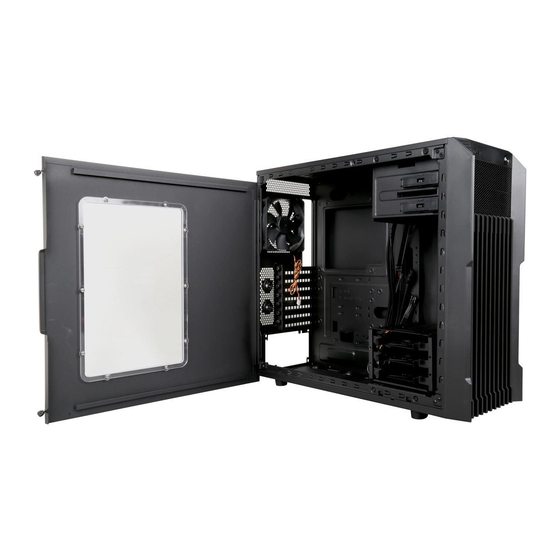
Page 4: Product Diagram
Stryker M Product Diagram Panel L Panel R Top Dust Filter 120 mm Fan 2.5” SSD Tray Front Panel 120 mm Fan x 2 HDD Tray HDD Cage Bottom Dust Filter Front I/O Pinout... -
Page 5: Front I/O Diagram
Stryker M Front I/O Diagram Accessory Kit Figure Part’s Name Used For Screw-A Motherboard Standoff Motherboard Screw-B ODD / HDD / SSD Screw-C Power Supply Unit Screw-D Cables / Wires Cable Tie Nut Setter Standoff Installation Buzzer Motherboard Alarm... -
Page 6: Open The Unit
Stryker M Open the Unit 1-1. Untwist the thumbscrews and slide out panels R and L (Figure 1). Install the Power Supply 2-1. Seat the power supply unit (PSU) to the bottom of the case and secure with Screw-C (Figure 2). -
Page 7: Install The Motherboard
Stryker M Install the Motherboard 3-1. Line up the standoffs with the screw holes 3-2. Screw the motherboard down with Screw-A on the motherboard (Figure 3a). (Figure 3b). Install the Add-in Card 4-1. Untwist the screws and remove the 4-2. Install the add-in card and secure with the slot cover (Figure 4a). - Page 8 Stryker M 5. Install an External 5.25” Device 5-2. Remove the slot cover (Figure 5b). 5-1. Pull the front panel out and remove it (Figure 5a). 5-3. Insert the 5.25” drive and push it back into the case. Make sure it’s secured. (Figure 5c).
- Page 9 Stryker M 6. Install a 3.5” or 2.5” Drive Use Screw-B on drive trays and cages. Refer to the Accessory Kit for reference. 6-1. 3.5” Drive: Install the 3.5” HDD onto the 6-2. 2.5” Drive: Screw the 2.5” SSD/HDD onto tray (secure with screws if desired) the tray with Screw-B (Figure 6b).
- Page 10 Stryker M 6-4. An additional 2.5” tray is located in the back of motherboard tray. Unscrew and remove the 2.5” tray (Figure 6e). 6.5. Secure the 2.5” HDD / SSD onto the tray 6-6. Screw the tray back onto the motherboard with Screw-B (Figure 6f).
- Page 11 Stryker M 7. Care To prevent damage, it is recommended to keep all panels closed and secured. 7-1. Slide the side panels back into place and secure with thumbscrews (Figure 7a). 7-2. To prevent overheating and damage, clean the dust filter regularly to ensure adequate airflow (Figure 7b &...
- Page 12 Stryker M 8. Options 8-1. Additional Fan Install The Stryker M has the capacity for extra fans: 120/140 mm fans under the top cover (x2) 140 mm fans in the front (x2) 120 mm fan on the bottom cover (x1) 8-2.
- Page 13 Stryker M 8-2.2. Top location installation: a. Remove the top dust filter (Figure 9a). b. Screw the radiator down and return the filter (Figure 9b).
-
Page 14: Specifications
Stryker M 9. Specifications Model Model Name Stryker M Item Number 11-147-244 Specs Type Mid Tower Color Black Case Material Steel/Plastic Power Supply Included Motherboard Compatibility ATX, Micro-ATX, Mini-ITX With Side Panel Window Expansion External 5.25" Drive Bays External 3.5" Drive Bays Internal 3.5"...
Need help?
Do you have a question about the strykerM and is the answer not in the manual?
Questions and answers