Table of Contents
Advertisement
Quick Links
Advertisement
Table of Contents

Related Manuals for Elation POWER SPOT 700CMY II


Summary of Contents for Elation POWER SPOT 700CMY II
-
Page 1: User Manual
POWER SPOT 700CMY II User Manual Revised 3/25/2008 visage Software version 1.5... - Page 2 Power Spot 700CMY II™ ©Elation Professional, Los Angeles Ca. www.ElationLighting.com...
-
Page 3: Table Of Contents
Power Spot 700CMY II™ CONTENTS General Information……………………………………………………………………… 4 a. Introduction………………………………………………………………………. 4 b. Unpacking………………………………………………………..…………..….. 4 c. Customer Support…………………………………………….………………… 4 d. Warranty Registration……………………………………………………..……. 5 e. Discharge Lamp Warning……………………………………………………… 5 Safety Instructions………………………………………………………..…………. 7 Features…………………………………………………………………………………... 8 General Guidelines………………………………………………………………………. 9 Fixture Overview…………………………………………………………………………. 11 Mounting and Installation………………………………………………………….……. 15 a. -
Page 4: Introduction
UNPACKING: Thank you for purchasing the Power Spot 700CMY II™ by Elation Professional®. Every Power Spot 700CMY II™ has been thoroughly tested and has been shipped in perfect operating condition. Carefully check the shipping carton for damage that may have occurred during shipping. - Page 5 Power Spot 700CMY II™ ©Elation Professional, Los Angeles Ca. www.ElationLighting.com...
-
Page 6: Warranty Registration
Power Spot 700CMY II™ WARRANTY REGISTRATION: The Power Spot 700CMY II™ carries a two-year (730 days) limited warranty. Please fill out the enclosed warranty card to validate your purchase. All returned service items whether under warranty or not, must be freight pre- paid and accompany a return authorization (R.A.) number. -
Page 7: Discharge Lamp Warning
Power Spot 700CMY II™ This risk is increased with age; added care is encouraged when dealing with older lamps. Thus, lamp should always be replaced at the end of their recommended duty cycle. Extreme caution should be used when operated this or any fixture fitted with a gas discharge lamp. -
Page 8: Safety Instructions
2. Never touch the fixture during normal operation. This can cause severe personnel injuries and/or damage to the fixture. 3. Be sure to unplug the POWER SPOT 700CMY II™ from the power outlet before performing any service related issues. 4. Lamp Replacement; Allow at least 15 minutes after disconnecting main power before you open the POWER SPOT 700CMY II™. -
Page 9: Features
Power Spot 700CMY II™ 3. FEATURES • Pan 530° / Tilt 285° • 3 operation mode: DMX controlled, stand alone or sound activated • Electronic Power Supply (100v~240v / 50Hz~60Hz) • Control board with 4-digit display • Digital display can be turned 180° to fit different installation position •... -
Page 10: General Guidelines
Power Spot 700CMY II™ 4. GENERAL GUIDELINES This fixture is a professional lighting effect designed for use on stage, in nightclubs, in theatres, etc. Do not attempt operation or installation without a proper knowledge on how to do so. This fixture was designed for indoor use only. - Page 11 Power Spot 700CMY II™ Transportation and Handling The POWER SPOT 700CMY II™ comes with two carrying handles built into the base. Always transport the fixture by these handles. Never lift or carry the POWER SPOT 700CMY II™ by the yoke (head assembly) this can seriously damage the unit and will void your manufactures warranty.
-
Page 12: Fixture Overview
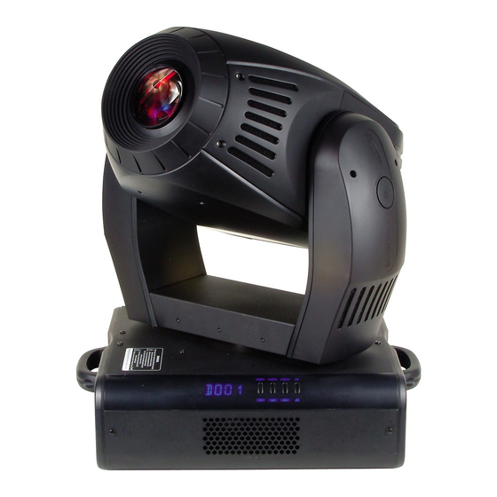
Power Spot 700CMY II™ 5. FIXTURE OVERVIEW 1. Moving Head 2. Carrying Handles 3. LED Menu Display 4. Head Tilt Lock 5. Omega Clamp 6. Ethernet Jack 7. 5-Pin DMX Out Connector 8. 5-Pin DMX In connector 9. Microphone Sensitivity 10. - Page 13 Power Spot 700CMY II™ Side View - Menu and Display 20.4-Segment LED Menu Display 22 23 24 21. Mode Button 22. Enter Button 23. Up Button 24. Down Button 1. Head Assembly – The head assembly consist of the main output lens, and either the standard or CMY control module.
- Page 14 Never defeat this fuse. This fuse is designed to protect the lamp in the event of severer power fluctuations. In the event of fuse failure, always be sure to replace this fuse with an exact match unless otherwise instructed by an authorized Elation ©Elation Professional, Los Angeles Ca.
- Page 15 Power Spot 700CMY II™ technician. 17. Internal Cooling Fan – This fixture is equipped with two high-velocity variable speed fans mounted in the base to aid in the cooling process. These fans are designed to vary their velocity at different operating temperatures. When the fixture reaches a predetermined internal operating temperature the fans function at high speeds.
-
Page 16: Mounting And Installation
MOUNTING The POWER SPOT 700CMY II™ is fully operational in two different mounting positions, hanging upside or set on a flat level surface. To avoid internal damage to the unit, never mount the unit on its side as illustrated below. Be sure this fixture is kept at least 1.5 feet away from any flammable materials (decoration etc.). -
Page 17: Mounting Points
Clamps The POWER SPOT 700CMY II™ has been designed to hold multiple clamps to the bottom of the unit in several different orientations. Always use an appropriately rated clamp to mount this unit to truss. Refer to the printed instructions on the bottom of the fixture for proper clamp installation. - Page 18 (each two opposite threads max. M10x20). Secure the POWER SPOT 700CMY II™ Regardless of the rigging option you choose for your POWER SPOT 700CMY II™ always be sure to secure your fixture with a safety cable. The fixture provides a built-in rigging point for a safety cable on the underside of the fixture, be sure to use this point and never secure a safety cable to a carrying handle.
-
Page 19: Understanding Dmx
DMX transmission and may be purchased from your Elation dealer or at most professional lighting retailers. Keep in mind that although microphone cable may look similar to DMX cable it does not share the same resistance rating and may be susceptible to line interference. -
Page 20: Dmx Terminator
Power Spot 700CMY II™ chained and cannot be split, unless using an approved DMX splitter such as the Elation Opto Branch 4™ or DMX Branch/4™. Be sure to follow the above figure when making your own cables. Do not use the ground lug on the XLR connector. - Page 21 2 and 3 of a male XLR connector (DATA + and DATA -). This fixture is inserted in the female XLR connector of the last fixture in your daisy chain to terminate the line. Using a line terminator (Elation part: DMX T PACK) will decrease the possibilities of erratic behavior.
- Page 22 In the case of the Power Spot 700CMY II™, which is a 24 channel fixture, you should set the starting DMX address of the first unit to 1, the second unit to 25 (24 + 1), the third unit to 49 (24 + 25), and so on.
-
Page 23: Fixture Menu
The control panel located on the side of the fixture allows you to access the main menu and make all necessary adjustments to the POWER SPOT 700CMY II™. During normal operation, tapping the “MODE” key once will access the fixture’s main menu. - Page 24 To set or adjust a DMX address, please follow the procedure below: 1. Switch on the POWER SPOT 700CMY II™ and wait for the fixture reset process to finished ('RST' will flash in the LED while fixture is in reset mode).
- Page 25 Power Spot 700CMY II™ The DMX address is non-destructible and will remain in the fixture’s memory even when the power has been switched off. Memory is backed-up and retained by an internal power source with a five year shelf life.
- Page 26 Power Spot 700CMY II™ 8.4 Lamp On/Off LAMP This function allows you to manually control the lamp operation. Access the lamp function in the main menu and use the use the Up and Down buttons to toggle between lamp On and lamp Off. Press the Enter button to confirm the operation or the Mode button to cancel and return to the main menu.
- Page 27 Power Spot 700CMY II™ Mode button to cancel and return to the main menu. 8.8 Invert Tilt Movement RTLT This function allows you to invert all tilt movements. Use the Up and Down buttons to turn this function On and Off. Press the Enter button to accept the change or the Mode button to cancel and return to the main menu.
- Page 28 Power Spot 700CMY II™ points, or testing. Use the Up and Down buttons to select the function you wish to adjust, then use the Enter button to accept your selection. Now adjust the values with the Up and Down buttons and use the Enter button to lock in your value.
- Page 29 Power Spot 700CMY II™ DLOF This function allows the lamp to be switched off through a DMX controller. To enable this function use the Up and Down buttons to toggle between ON and Off. Turn this function “ON” to allow DMX switching. Use the Enter button to accept your selection or the Mode button to cancel and return to the menu.
- Page 30 Power Spot 700CMY II™ 8.10.5 Display DISP Use this function to choose between different display indications. Use the Up/Down-keys to select desired function and press Enter to confirm or Mode to cancel and return to the menu. D ON Display On/Off (If you've chosen off, the display will go out within 15 seconds after the last input.
- Page 31 Power Spot 700CMY II™ HIGH The cooling fan works continuously at max. speed. This is the default fan setting. In this setting an internal thermal sensor constantly monitors the internal operating temperature and regulates the fan speed to coincide with the internal temperature.
- Page 32 Power Spot 700CMY II™ and press the Enter button to confirm the adjustment or the Mode button to cancel and return to the menu. Use the Up and Down buttons to set the adjustment values and confirm once more with the Enter button or use the Mode button to cancel the operation.
- Page 33 8.10.12 Feedback ”APC” FEED The POWER SPOT 700CMY II™ is equipped with ”APC,” automatic position correction. This function automatically corrects the Pan and Tilt movement should the unit lose step or is obstructed and forced to lose step. Press the Enter button to access the sub-menu.
- Page 34 Power Spot 700CMY II™ This message appears if you try to switch on the lamp within 5 minutes HEAt after having switched off (lamp too hot). The message will appear on the display if the lamp doesn’t ignite within 20 seconds. The fixture will store this command and automatically ignite the lamp after 5 minutes.
-
Page 35: Operation
A DMX controller allows you to create unique programs tailored to your individual needs. The Power Spot 700CMY II™ uses 24 DMX channels. See page 36 for detailed description of the DMX traits. To control your fixture in DMX mode, follow the set-up procedures beginning on page 21 as well as the set-up specifications that are included with your DMX controller. - Page 36 Power Spot 700CMY II™ to the audio submenu. See page 23 for the menu breakdown. 9.2.3 In the audio submenu choose the audio chase speed, fast or slow. Slow (ASLW) will trigger the chase sequence to every two beats, while fast (AFST) will trigger the chase impulse every beat.
- Page 37 Power Spot 700CMY II™ ©Elation Professional, Los Angeles Ca. www.ElationLighting.com...
- Page 38 Power Spot 700CMY II™ 10. DMX CHANNEL SELECTION (DMX PROTOCOL) Channel Function Time and Value 1) Pan 0..530° Min. 2.65 s 0..255 00..FF 0..100 High-Pos ... High-Pos + 2.1° (16 2) Pan-fine 0..255 00..FF 0..100 Bit) 3) Tilt 0..285° Min. 1.8 s 0..255...
- Page 39 Power Spot 700CMY II™ Channel Function Time and Value Color 2 / Color 3 (slow) 74..75 4A..4B 29.2 Color 3. Yellow (slow) 76..77 4C..4D 30.0 Color 3 / Color 4 (slow) 78..79 4E..4F 30.8 Color 4. Purple (slow) 80..81 50..51 31.6 Color 4 / Color 5 (slow) 82..83...
- Page 40 Power Spot 700CMY II™ Channel Function Time and Value 18..20. Gobo 7 (fast) 48..55 30..37 Gobo 8 (fast) 56..63 38..3F 21..23 24..26. Gobo 1 (open. slow) 64..71 40..47 Chaser from gobo to 27..29. gobo max. 40 BPM Gobo 2 (slow) 72..79...
- Page 41 Power Spot 700CMY II™ Channel Function Time and Value (fast) Gobo 2 (fast) gobo max. 100 BPM 4..7 04..07 2..3 => 0.6 s Gobo 3 (fast) 8..11 08..0B 3..4 Gobo 4 (fast) 12..15 0C..0F 5..6 Gobo 5 (fast) 16..19 10..13 6..7 Gobo 6 (fast) 20..23...
- Page 42 Power Spot 700CMY II™ Channel Function Time and Value Max. frequency 10 Strobe effect, slow - fast 64..239 40..EF 26..93 Shutter open (lamp start) 240..255 F0..FF 94..100 13) Dimmer Dimmer closed (0%) 0..3 0..3 0..1 Movement time 0.3 Dimmer 1%...99% 4..251...
- Page 43 Power Spot 700CMY II™ Channel Function Time and Value swing Effect Rotating slow - fast CW 0..127 00..7F 0..49 wheel Posi./Rot Rotating fast - slow CCW 128...255 80..FF 50..100 22) Special No Function 0..15 00..0F 0..6 Gobo1-shake +/- 10° 3.5 moves / min. up 16..31...
- Page 44 Power Spot 700CMY II™ Channel Function Time and Value 270° 06..07 06..07 2.5 0° 08..09 08..09 3.3 90° 10..11 0A..0B 4.1 180° 12..13 0C..0D 4.9 270° 14..15 0E..0F 5.7 0° 16..17 11..11 6.5 90° 18..19 12..13 7.3 180° 20..21 14..15 8.0 270°...
- Page 45 Power Spot 700CMY II™ of 3 sec.) if Shutter closed '000' Channel 12 Channel 22 250..25 FA..F 98..10 Reset ©Elation Professional, Los Angeles Ca. www.ElationLighting.com...
-
Page 46: Lamp Replacement
• Don’t touch the bulb of the lamp with bare fingers (this can cause damages. • Before you put the POWER SPOT 700CMY II™ into operation close the casing, otherwise you risk damage to the retina and expose to UV radiation! •... -
Page 47: Lamp Optimization
Power Spot 700CMY II™ 4. Using a standard flat head screwdriver release 1/4 turn quick-lock fasteners (labeled 1, 2, 3, and 4) of the backside lamp sheet and remove it carefully. These fasteners will remain connected to the lamp socket cover. - Page 48 Power Spot 700CMY II™ 1. Using a flathead screwdriver move the lamp position with setscrew “B” forwards and backwards until a very bright luminous spot (hotspot) can been seen clearly. 2. Move lamp with setscrew “A” upward/downwards until this hotspot is in the center of the beam projection.
-
Page 49: Fuse Replacement
Caution: Always replace with the exact same type fuse, unless otherwise specified by an authorized Elation® service technician. Replacing with anything other than the specified part can damage your unit and will void your manufactures warranty. -
Page 50: Optical Effects Module
Power Spot 700CMY II™ 13. OPTICAL EFFECTS MODULE The Power Spot 700CMY II is equipped with an optical effects module that can be easily removed for cleaning, service, and gobo/color exchange. Please follow the procedures below for proper removal and service of the effects module. - Page 51 Power Spot 700CMY II™ No other bus cables need to be removed. See illustration below; Data Bus 4) Loosen the two locking thumbscrews on the left and right side of the optical effects module (please do not attempt to remove the thumbscrews completely).
- Page 52 Power Spot 700CMY II™ sensitive wheel components like the gobo and color wheels or any cables to remove the module. Use the metal support plates or the stepper motors as a means to grasp the module. 5) To access the internal components of the module loosen the three securing thumbscrews illustrated below.
-
Page 53: Changing/Replacing Gobos/Colors
(section 13) of this manual. The POWER SPOT 700CMY II includes both Aluminum (thickness = 0.3 mm) and Glass (thickness = 1.1 - 3.0 mm) gobos (outside diameter 26.9 mm, viewable image size 23 mm). - Page 54 Power Spot 700CMY II™ Attention: Custom gobos that contain company logos and text must also be orientated properly to ensure proper display of the custom image. The readable side must be mounted towards the lamp. In the illustration below, notice that the text is readable in the example on the left and mirrored in the example on right.
- Page 55 Power Spot 700CMY II™ 2) Genteelly lift and pull the gobo holder out of the center part of the wheel hub to remove the individual holder. See the left image below. 3) Once the gobo holder has been removed the Gobo itself can be replaced by remove the centric spring with a small screwdriver or gripping pliers.
-
Page 56: Gobo Patterns
Power Spot 700CMY II™ Gobo Patterns: OPEN 29.8mm Gobo wheel 1 with rotating Gobos Gobo wheel 2 with fixed Gobos ©Elation Professional, Los Angeles Ca. www.ElationLighting.com... -
Page 57: Animation Wheel
Power Spot 700CMY II™ 15. ANIMATION WHEEL The Power Spot 700CMY II is equipped with an animation wheel that can simulate effects such as running water, fire, clouds, and others. The unit ships with the fire effect wheel already installed. Four optional wheels are included in the accessory pack. Follow the procedures outlined below for proper effects wheel exchange: 15.1 Safety considerations:... - Page 58 Power Spot 700CMY II™ detailed in the illustration on the below. This thumbscrew holds an angled aluminum bar in place. 15.2.4 Fold the angled bar out of the way and pull the animation wheel up and out of the optical path. Once the animation wheel is exposed it can be exchanged with the use of any tools.
- Page 59 Power Spot 700CMY II™ 15.2.6 After the animation wheel is exchanged resemble the fixture in reverse order. Be sure the effects wheel is completely seated on the magnetic axis hub and that all screws are fastened completely before attempting operation.
- Page 60 Power Spot 700CMY II™ 25-022-1098 Optional 25-022-1095 Optional ©Elation Professional, Los Angeles Ca. www.ElationLighting.com...
- Page 61 Power Spot 700CMY II™ 16. MAINTENANCE AND CLEANING THE POWER SPOT 700CMY II™ It is absolutely essential that the fixture is kept clean and dust, dirt and smoke-fluid residues do not built-up on the surface or within the fixture. Residue build-up may cause the fixture's light output to be significantly reduced.
- Page 62 Power Spot 700CMY II™ Dimmer/Shutter Yearly Vacuum cleaner, airbrush, etc. Inside lens Monthly Soft cloth no glass cleaner Fan and air channel Monthly Vacuum cleaner, airbrush, etc. Reflector Never Lamp Never Moveable parts Yearly Suitable Lubricant Caution: 1. Never allow the optical parts to come in contact with oil, dirt, or grime.
-
Page 63: Warranty
It is the owner’s responsibility to establish the date and place of purchase by acceptable evidence, at the time service is sought. B. For warranty service, send the product only to the Elation Professionals® factory. All shipping charges must be pre-paid. If the requested repairs or service (including parts replacement) are within the terms of this warranty, Elation Professionals®... - Page 64 Professionals® be liable for any loss or damage, direct or consequential, arising out of the use of, or inability to use, this product. G. This warranty is the only written warranty applicable to Elation Professionals® products and supersedes all prior warranties and written descriptions of warranty terms and conditions heretofore published.
-
Page 65: Photometric Data
Power Spot 700CMY II™ 18. PHOTOMETRIC DATA ©Elation Professional, Los Angeles Ca. www.ElationLighting.com... - Page 66 Power Spot 700CMY II™ 19. DIMENSIONS ©Elation Professional, Los Angeles Ca. www.ElationLighting.com...
-
Page 67: Technical Specifications
Power Spot 700CMY II™ 20. TECHNICAL SPECIFICATION Power supply Power consumption 90 ~ 260V, 50 ~ 60 Hz 1000 Watt, 4.5 A, electronic ballast, (blind current compensated) Fuse protection Lamp 120v: GMA 10A, 250V, 5x20 mm (fine-wire fuse) Electronic 120v: GMA 2A, 250V, 5x20 mm (fine-wire fuse) - Page 68 Power Spot 700CMY II™ Zoom (8/16 Bit) Zoom range 14° - 32° CTO Filter (8/16 Bit) Variable CTO color correction filter 0 - 100% (7500K ~ 3200K in white) Effect wheel (8 Bit) Rotating and indexed Effect wheel, different patterns, exchangeable Drive Standard USITT DMX-512, 3 pole XLR;...
- Page 69 Power Spot 700CMY II™ INDEX Adjustments.......... 23 Injury of the retina ........7 Aspheric lens .......... 40 Maintenance ........... 39 BGV C1 ..........11 Measures ..........41 Blind current compensation ....13 Mounting..........11 Calibrations........... 23 Pan- movement ........41 Change a Gobo ........
- Page 70 Power Spot 700CMY II™ ©Elation Professional, Los Angeles Ca. www.ElationLighting.com...
- Page 71 Power Spot 700CMY II™ ©Elation Professional, Los Angeles Ca. www.ElationLighting.com...
- Page 72 Power Spot 700CMY II™ Elation Professional 6122 S Easter Ave Los Angeles, CA. 90040 323-582-3322 / 323832-9142 fax www.ElationLighting.com / info@ElationLighitng.com ©Elation Professional, Los Angeles Ca. www.ElationLighting.com...
Need help?
Do you have a question about the POWER SPOT 700CMY II and is the answer not in the manual?
Questions and answers