Table of Contents
Advertisement
Quick Links
XP-EV600/EV600B/EV600D
QQ
3 7 63 1515 0
SERVICE MANUAL
Ver 1.3 2003. 12
TE
L 13942296513
www
.
Sony Corporation
9-877-195-04
2003L16-1
Personal Audio Company
© 2003.12
Published by Sony Engineering Corporation
http://www.xiaoyu163.com
System
Compact disc digital audio system
Laser diode properties
Material: GaAlAs
Wavelength: λ = 780 nm
Emission duration: Continuous
Laser output: Less than 44.6 µW (This output is the value
measured at a distance of 200 mm from the objective lens
surface on the optical pick-up block with 7 mm aperture.)
Power requirements
For the area code of the model you purchased, check the
upper left side of the bar code on the package.
• Two LR6 (size AA) batteries: 3 V DC
• Two Ni-MH rechargeable batteries (size AA) (Sony
NH-7WMAA or equivalent): 2.4 V DC
• AC power adaptor (DC IN 4.5 V jack)
Dimensions (w/h/d) (without projecting
parts and controls)
Approx. 136 × 20.4 × 139 mm
x
ao
u163
y
i
http://www.xiaoyu163.com
2 9
8
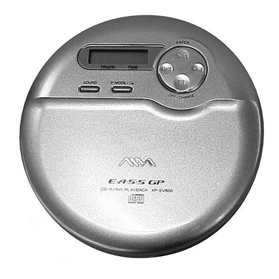
Photo: XP-EV600
Model Name Using Similar Mechanism D-EJ760
CD Mechanism Type
Optical Pick-up Name
SPECIFICATIONS
Q Q
3
6 7
1 3
1 5
Mass (excluding accessories)
Approx. 175 g
Operating temperature
5°C – 35°C
Supplied Accessories
XP-EV600:
Earphones with remote control (1)
AC power adaptor (1)
XP-EV600B:
Earphones with remote control (1)
AC power adaptor (1)
Rechargeable batteries (2)
Battery carrying case (1)
XP-EV600D:
Earphones with LCD remote control (1)
AC popwer adaptor (1)
Rechargeable batteries (2)
Battery carrying case (1)
Design and specifications are subject to change without
notice.
co
.
9 4
2 8
AEP Model
UK Model
XP-EV600/EV600B
E Model
Australian Model
Chinese Model
XP-EV600B/EV600D
CDM-3325ER
DAX-25E
0 5
8
2 9
9 4
2 8
m
PORTABLE CD PLAYER
9 9
XP-EV600D
9 9
Advertisement
Table of Contents

Related Manuals for Sony XP-EV600


Summary of Contents for Sony XP-EV600
-
Page 1: Te L 13942296513
Earphones with LCD remote control (1) • Two LR6 (size AA) batteries: 3 V DC AC popwer adaptor (1) • Two Ni-MH rechargeable batteries (size AA) (Sony Rechargeable batteries (2) NH-7WMAA or equivalent): 2.4 V DC Battery carrying case (1) •... -
Page 2: Table Of Contents
COMPONENTS IDENTIFIED BY MARK 0 OR DOTTED LINE WITH MARK 0 ON THE SCHEMATIC DIAGRAMS AND IN THE PARTS LIST ARE CRITICAL TO SAFE OPERATION. REPLACE THESE COMPONENTS WITH SONY PARTS WHOSE PART NUMBERS APPEAR AS SHOWN IN THIS MANUAL OR IN SUPPLEMENTS PUBLISHED BY SONY. -
Page 3: Servicing Note
XP-EV600/EV600B/EV600D SECTION 1 SERVICING NOTE 3 7 63 1515 0 BEFORE REPLACING THE OPTICAL PICK-UP BLOCK NOTES ON HANDLING THE OPTICAL PICK-UP Please be sure to check thoroughly the parameters as par the “ O ptical BLOCK OR BASE UNIT Pick-Up Block Checking Procedures ”... -
Page 4: General
*The button has a tactile dot. CD player (rear/inside) L 13942296513 Open the battery Insert the ( end first (for both compartment lid. batteries). 8E•A•S•S Remote control (XP-EV600/EV600B) Remote control (XP-EV600D only) 3tF SKIP Display 7VOL +/– 7VOL 2SOUND 3r/t... -
Page 5: Disassembly
XP-EV600/EV600B/EV600D SECTION 3 DISASSEMBLY 3 7 63 1515 0 Note : Disassemble the unit in the order as show n below . LOWER CABINET SECTION, SUB BOARD CABINET (FRONT) SUB ASSY CD MECHANISM SECTION (CDM-3325ER) UPPER LID SUB ASSY... -
Page 6: Lower Cabinet Section, Sub Board
XP-EV600/EV600B/EV600D 3 7 63 1515 0 Note : Follow the disassembly procedure in the numerical order giv e n. 3-1. Lower Cabinet Section, SUB Board 3 six screws (B2) 2 two screws (B2) 1 Open the battery lid. L 13942296513 5 Remove the cabinet (front) assy. -
Page 7: Cd Mechanism Section (Cdm-3325Er)
XP-EV600/EV600B/EV600D 3 7 63 1515 0 3-2. CD Mechanism Section (CDM-3325ER) CD mechanism three insulators (CDM-3325ER ) connector (2P) (CN403) connector (4P) (CN402) flexible board (15P) (CN401) L 13942296513 u163 http://www.xiaoyu163.com... -
Page 8: Cabinet (Front) Sub Assy
XP-EV600/EV600B/EV600D 3 7 63 1515 0 3-3. Cabinet (front) Sub Assy 3 Remove the open right spring in 1 Remove the open left spring in 2 open left spring the direction of the arrow. the direction of the arrow. -
Page 9: Upper Lid Sub Assy
XP-EV600/EV600B/EV600D 3 7 63 1515 0 3-4. Upper Lid Sub Assy upper lid sub assy control button rubber liquid crystal display panel L 13942296513 switch unit assy lid cover seven screws u163 http://www.xiaoyu163.com... -
Page 10: Main Board
XP-EV600/EV600B/EV600D 3 7 63 1515 0 3-5. MAIN Board 2 battery terminal board (relay) 3 MAIN board 1 Remove the soldering. L 13942296513 3-6. Motor Assy (sled) (M902), Optical Pick-up (DAX-25E), Turn Table Motor Assy (spindle) (M901) 1 three screws (B1.7x4) -
Page 11: Electrical Checking
XP-EV600/EV600B/EV600D SECTION 4 ELECTRICAL CHECKING 3 7 63 1515 0 RF Level Check The CD section adjustments are done automatically in this set. In case of operation check, confirm that RF level. Condition: • Hold the set in horizontal state. -
Page 12: Diagrams
XP-EV600/EV600B/EV600D SECTION 5 DIAGRAMS 3 7 63 1515 0 NOTE FOR PRINTED WIRING BOARDS AND SCHEMATIC DIAGRAMS Note on Printed Wiring Board Note on Schematic Diagram: • All capacitors are in µF unless otherwise noted. pF: µµF 50 WV or •... -
Page 13: Block Diagram
XP-EV600/EV600B/EV600D 3 7 6 3 1 5 1 5 0 5-1. Block Diagram OPTICAL PICK-UP DIGITAL SERVO BLOCK MEMORY CONT/ (DAX-25E) DLGLTAL HI & BUS B00ST HEADPHONE AMP IC402 IC701 VCC2 J701 A OUT1 L IN L OUT RFAC... -
Page 14: Printed Wiring Board - Main Board (Side A)
XP-EV600/EV600B/EV600D 5-2. Printed Wiring Board – MAIN Board (SIDE A) – 3 7 6 3 1 5 1 5 0 S302 S301 MAIN BOARD (SIDE A) • Semiconductor S303 (OPEN/CLOSE) Location L208 R214 Ref. No. Location M902 TAP304 (VL) -
Page 15: Printed Wiring Board - Main Board (Side B)
XP-EV600/EV600B/EV600D 5-3. Printed Wiring Board – MAIN Board (SIDE B), SUB Board – 3 7 6 3 1 5 1 5 0 • Semiconductor MAIN BOARD (SIDE B) Location Ref. No. Location D204 F-11 D205 E-10 TP443 D206 E-10... -
Page 16: Schematic Diagram - Main Board (1/4)
XP-EV600/EV600B/EV600D 5-4. Schematic Diagram – MAIN Board (1/4) – • See page 12 for Waveforms. • See page 20 for IC Block Diagrams. 3 7 6 3 1 5 1 5 0 R720 C423 C424 C422 R435 C434 2.2k... -
Page 17: Schematic Diagram - Main Board
XP-EV600/EV600B/EV600D 5-5. Schematic Diagram – MAIN Board (2/4), SUB Board – • See page 20 for IC Block Diagrams. 3 7 6 3 1 5 1 5 0 J381 FB381 FB382 CN381 CN382 R382 220k J701 R716 TP703 TJ701... -
Page 18: Schematic Diagram - Main Board (3/4)
XP-EV600/EV600B/EV600D 5-6. Schematic Diagram – MAIN Board (3/4) – • See page 20 for IC Block Diagrams. 3 7 6 3 1 5 1 5 0 CN403 TP414 TP413 L211 TP409 TP410 TP411 TP412 CN402 R211 D206 MA111-TX Q203... -
Page 19: Schematic Diagram - Main Board (4/4)
XP-EV600/EV600B/EV600D Ver 1.1 2003.06 5-7. Schematic Diagram – MAIN Board (4/4) – • See page 12 for Waveforms. 3 7 6 3 1 5 1 5 0 R313 R312 C306 4700p R324 C316 4700p C301 4700p C310 4700p C302... -
Page 20: Ic Block Diagram
XP-EV600/EV600B/EV600D 5-8. IC Block Diagram 3 7 6 3 1 5 1 5 0 IC402 CXD3048R IC201 BH6580KV 52 51 48 47 44 43 AVDD DCIN HV PROT H BRIDGE H BRIDGE H BRIDGE MIRR 40 LATCH ASYMMETRY DIGITAL... -
Page 21: Ic Pin Function Description
XP-EV600/EV600B/EV600D 3 7 63 1515 0 5-9. IC Pin Function Description • IC301 T5AW-C7 (µCOM)(XP-EV600/EV600B) / T5AJ4-C7 (µCOM)(XP-EV600D) Pin No. Pin Name Description — Ground (digital) System clock input from CXD3048R(IC402) XOUT Not used TEST Test pin (normally connected to ground) VDD1 —... - Page 22 XP-EV600/EV600B/EV600D 3 7 63 1515 0 Pin No. Pin Name Description FG_I FG pulse signal input from BH6580KV-F(IC201) PGMSEL_O Not used PWRSW_O Power supply control output of TA2120FN(IC701) (“ H ” : ON) XPOWLT_O Latch signal output to BH6580KV-F(IC201)
-
Page 23: Cabinet Upper Section
XP-EV600/EV600B/EV600D SECTION 6 EXPLODED VIEWS 3 7 63 1515 0 NOTE: • -XX and -X mean standardized parts, so they • The mechanical parts with no reference num- The components identified by mark 0 or may have some difference from the original ber in the exploded views are not supplied. -
Page 24: Cabinet Lower Section
XP-EV600/EV600B/EV600D 3 7 63 1515 0 6-2. Cabinet Lower Section CD mechanism section (CDM-3325ER) not supplied not supplied L 13942296513 Ref. No. Part No. Description Remarks Ref. No. Part No. Description Remarks 3-245-331-02 INSULATOR 3-249-054-11 CABINET, LOWER (EV600D) * 53... -
Page 25: Cd Mechanism Deck Section (Cdm-3325Er)
XP-EV600/EV600B/EV600D 3 7 63 1515 0 6-3. CD Mechanism Deck Section (CDM-3325ER) M901 L 13942296513 M902 Ref. No. Part No. Description Remarks Ref. No. Part No. Description Remarks 3-318-203-61 SCREW (B1.7X4), TAPPING 3-221-475-01 SHAFT, STANDARD 0 102 X-3380-950-1 OPTICAL PICK-UP (DAX-25E) -
Page 26: Electrical Parts List
XP-EV600/EV600B/EV600D Ver 1.2 2003.08 SECTION 7 MAIN ELECTRICAL PARTS LIST 3 7 63 1515 0 NOTE: • Items marked “ * ” are not stocked since they • Due to standardization, replacements in the • Abbreviation parts list may be different from the parts speci- are seldom required for routine service. - Page 27 XP-EV600/EV600B/EV600D MAIN 3 7 63 1515 0 Ref. No. Part No. Description Remarks Ref. No. Part No. Description Remarks C432 1-164-156-11 CERAMIC CHIP 0.1uF < IC > C433 1-110-569-11 TANTAL. CHIP 47uF 20.00% 6.3V IC201 6-703-034-01 IC BH6580KV C434...
- Page 28 XP-EV600/EV600B/EV600D Ver 1.1 2003.06 MAIN 3 7 63 1515 0 Ref. No. Part No. Description Remarks Ref. No. Part No. Description Remarks R215 1-216-845-11 METAL CHIP 100K 1/16W R415 1-216-837-11 METAL CHIP 1/16W R216 1-216-845-11 METAL CHIP 100K 1/16W...
- Page 29 XP-EV600/EV600B/EV600D Ver 1.3 2003.12 MAIN 3 7 63 1515 0 Ref. No. Part No. Description Remarks Ref. No. Part No. Description Remarks < VARISTOR > 3-252-476-41 MANUAL, INSTRUCTION (A) DHC-7 VDR201 1-801-862-11 VARISTOR, CHIP (1608) (POLISH,HUNGARIAN) (EV600:AEP/EV600B:AEP) VDR202 1-801-862-11 VARISTOR, CHIP (1608)
- Page 30 XP-EV600/EV600B/EV600D 3 7 63 1515 0 REVISION HISTORY Clicking the version allows you to jump to the revised page. Also, clicking the version at the upper right on the revised page allows you to jump to the next revised page.
Need help?
Do you have a question about the XP-EV600 and is the answer not in the manual?
Questions and answers