Table of Contents
Advertisement
Quick Links
Advertisement
Table of Contents

Related Manuals for Elan SS1


Summary of Contents for Elan SS1
-
Page 3: Safety Information
If the provided plug does not fit your outlet, consult an electrician for replacement of the obsolete outlet. Water —Do not use the device near water. © ELAN Home Systems 2007 • All rights reserved. Page 1... - Page 4 • Connect the equipment into an outlet on a circuit different from that to which the receiver is connected. • Consult the dealer or an experienced radio/TV technician for help. CAUTION: Changes or modifications not expressly approved by Elan Home Systems could void the user’s authority to operate the equipment.
-
Page 5: Table Of Contents
VIA!2-8.4 Wireless Touch Panel w/ Wired VIA! Touch Panels ............Wired VIA! Touch Panels and Olé Touchpads - ELAN Z•System ..........Wireless VIA!2-8.4 and Wired VIA! Touch Panels and Olé Touchpads - ELAN Z•System .... Wired VIA! Touch Panels and Olé Touchpads - ELAN System6 ............ - Page 6 SS1 Power ............................5. Programming ............................Setup Procedures ..........................Download Procedures ........................Download Enable Button ........................SS1 System Station Diagnostics ...................... Reboot ..............................6. Troubleshooting ..........................Warranty Back Page ............................Page 4 © ELAN Home Systems 2007 • All rights reserved.
-
Page 7: Introduction
INSTALLATION MANUAL 1. Introduction The SS1 System Station is an RS-232, IR, Sense and Relay controller all rolled into one. It is also the companion component to the VIA!2-8.4 Wireless Touch Panel, translating the wire- less panel’s 802.11g WiFi commands into actions that can control just about every aspect of a Home Theater or a zone in an ELAN multi-room system. -
Page 8: Specifications
IR Link ......................... DB-15 Connector VIA! Net ......................ELAN Standard RJ-45 Release Notes • One SS1 System Station is required for each VIA!2-8.4 Wireless Touch Panel • A dedicated network and wireless access point (WAP) is recommended for the VIA!2-8.4 Page 6... -
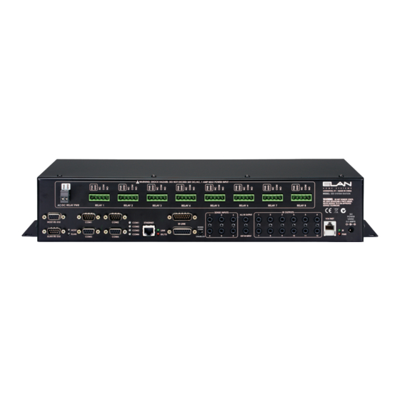
Page 9: Ss1 Rear Panel
Connect to ELAN 1-way RS-232 devices. Connection Block. Sense Inputs Connect ELANSENSE Sensors to create Trig- gers for automated events. Use VIA!TOOLS to program sequences that control RS-232 or IR devices. © ELAN Home Systems 2007 • All rights reserved. Page 7... -
Page 10: System Design & Applications
VIA!TOOLS Setup Software. Connect serial cables or Cat-5 (w/ DB-9 connectors) between the COM1-4 ports on the SS1 and the RS-232 device’s COM ports. COM1 and COM2 have Transmit/ Receive reversed compared to COM3 and COM4. Make sure to use the correct ports for the correct RS-232 controlled devices! VIA!TOOLS setup software will help to determine which device should be assigned to a particular COM port. - Page 11 IR controlled devices should typically be installed in close proximity to the SS1 System Station. Connect single and dual IR emitters between the IR ports of the SS1 and the IR sensor window (or 3.5mm IR input jack) of the source to be controlled. Use VIA!TOOLS setup software to create IR control functions and independent IR routing.
-
Page 12: Zone/System Wire Run Specifications And Via!Net Overview
INSTALLATION MANUAL Zone/System Wire Run Specifications and VIA!NET Overview The communication link between a Zone or System SS1 and all the wired or wireless VIA! Touch Panels and Olé Touchpads in a system is called the ‘VIA!NET’. All VIA!NET wire runs are “home-run”... - Page 13 250 ft VIA! #2 500 ft = 250 ft VIA!2-8.4/SS1 #3 VIA! #4 1000 ft Wireless _________________ Touch Panel Total 2000 ft Figure 2.2 - BASIC VIA!NET Wire Run Lengths © ELAN Home Systems 2007 • All rights reserved. Page 11...
-
Page 14: Extended Via!Net
An EXTENDED VIA!NET has the following specifications and limitations: • Capable of supporting one System SS1 and a maximum of 30 wired VIA! Touch Panels, wireless VIA!2 Touch Panels (with their companion Zone SS1s) and/or Olé Touchpads (same as BASIC VIA!NET). -
Page 15: Via!Net Repeaters
Green (Pin 5) - ZNet 485 - White/Green (Pin 6) - ZNet 485 + Brown (Pin 7) - N/C 87654321 White/Brown (Pin 8) - N/C Figure 2.5 - VIA!NET Pinout © ELAN Home Systems 2007 • All rights reserved. Page 13... -
Page 16: System Types
SYSTEM applications are used when an SS1 is performing tasks outside of being the con- trol center for a VIA!2-8.4 Wireless Touch Panel. Often, a System SS1 is linked to an ELAN Multi-Room Controller-based system. These applications can control local IR sources, sys- tem-wide IR sources, ELAN Multi-Room Controllers, one and two-way RS-232 devices, relay controlled devices, and perform intelligent ON/OFF commands through the Sense Inputs. -
Page 17: Stand-Alone Applications
VIA!2-8.4 Wireless Home Theater System Control The SS1 System Station makes an excellent STAND-ALONE Home Theater Controller. Figure 2.6 shows a STAND-ALONE SS1 System Station providing IR A/V source control, relay control of lifts, screens, and drapes, Ethernet control of a VIA!dvdj, and automated functionality using ELANSENSE Sensors. -
Page 18: Via!2-8.4 Wireless Home Theater System Control W/ One-Way
VIA!2-8.4 Wireless Home Theater System Control w/ One-Way RS-232 Control Figure 2.7 shows a STAND-ALONE application using the SS1 as a wireless connection hub and providing IR A/V source control, relay control of lifts, screens, and drapes, Ethernet control of a VIA!dvdj, one-way RS-232 control of local systems, and automated functionality using ELANSENSE Sensors. -
Page 19: Zone Applications
ZONE Applications VIA!2-8.4 Wireless Zone Control Zone applications utilize the SS1 as a control hub for a wireless VIA!2-8.4 Touch Panel (ZONE application) used as a controller for a zone of an ELAN Multi-Room Controller. One- way RS-232 control is available for devices that are only controlled from the zone in which the VIA!2-8.4 Touch Panel is assigned (local Home Theater equipment, for example). -
Page 20: Via!2-8.4 Wireless Zone Control W/ Multiple Wireless Touch Panels
INSTALLATION MANUAL VIA!2-8.4 Wireless Zone Control w/ Multiple Wireless Touch Panels This application uses two VIA!2-8.4 Wireless Touch panels as ZONE controllers for an ELAN multi-room system. These wireless panels provide IR A/V source control, relay control, one-way control of local RS-232 devices, and automated functionality using ELANSENSE Sensors in their own zones (Zones 1 and 2). -
Page 21: System Applications
SYSTEM Applications Basic Wired VIA! Touch Panel SYSTEM SS1 applications involve the use of the SS1 in conjunction with wired VIA! Touch panels, Olé Touchpads and (often) ELAN Multi-Room Controllers. IR system control, IR source control, Relay functions, Sense Input functions and one or two-way RS-232 control are possible, as well. -
Page 22: Multiple Wired Via! Touch Panels & Olé Touchpad
PVIA4 RS-232 1 & 2-Way Home Theater RS-232 Controlled Components Devices (x4) IR Emitter ® ELAN SENSE IR Emitter Sensors IR Emitter Figure 2.11 - Multiple Wired VIA!/Olé System Page 20 © ELAN Home Systems 2007 • All rights reserved. -
Page 23: Via!2-8.4 Wireless Touch Panel W/ Wired Via! Touch Panels
VIA!Net RS-232 Devices (x4) IR Controlled Components Gate Garage Door IR Emitter IR Emitter ELAN SENSE Sensors IR Emitter Relay Controlled Devices (x8) Figure 2.12 - WirelessVIA!/Wired VIA!/Olé System © ELAN Home Systems 2007 • All rights reserved. Page 21... -
Page 24: Wired Via! Touch Panels And Olé Touchpads - Elan Z•System
INSTALLATION MANUAL Wired VIA! Touch Panels and Olé Touchpads - ELAN Z•System This application uses wired VIA! Touch Panels and Olé Touchpads controlling an ELAN Z•630 Mult-Room Controller as well as Relay devices, local and system IR sources, ELANSENSE devices and one or two-way RS-232 devices. A PVIA10 Precision Panel is used in this SYSTEM application. -
Page 25: Wireless Via!2-8.4 And Wired Via! Touch Panels And Olé Touchpads - Elan Z•System
This application uses both a wireless VIA!2-8.4 and wired VIA! Touch Panels and Olé Touchpads controlling an ELAN Z•630 Mult-Room Controller as well as Relay devices, Local and System IR sources, ELANSENSE devices and one or two-way RS-232 devices. Two SS1s are used in this application: one as a wireless hub for the VIA!8.4 Wireless Touch Panel... -
Page 26: Wired Via! Touch Panels And Olé Touchpads - Elan System6
INSTALLATION MANUAL Wired VIA! Touch Panels and Olé Touchpads - ELAN System6 This application uses wired VIA! Touch Panels and Olé Touchpads controlling an ELAN System6 Mult-Room Controller as well as Relay devices, local and system IR sources, ELANSENSE devices and one or two-way RS-232 devices. A PS12 Precision Panel is used in this SYSTEM application. -
Page 27: Wireless Via!2-8.4 And Wired Via! Touch Panels And Olé Touchpads - Elan System6
ELAN System6 This application uses both a wireless VIA!2-8.4 and wired VIA! Touch Panels and Olé Touchpads controlling an ELAN System6 Mult-Room Controller as well as Relay devices, Local and System IR sources, ELANSENSE devices and one or two-way RS-232 devices. -
Page 28: Wired Via! Touch Panels And Olé Touchpads - Elan System12
INSTALLATION MANUAL Wired VIA! Touch Panels and Olé Touchpads - ELAN System12 This application uses wired VIA! Touch Panels and Olé Touchpads controlling an ELAN System12 Mult-Room Controller as well as Relay devices, local and system IR sources, ELANSENSE devices and one or two-way RS-232 devices. A PS12 Precision Panel is used in this SYSTEM application. -
Page 29: Wireless Via!2-8.4 And Wired Via! Touch Panels And Olé Touchpads - Elan System12
ELAN System12 This application uses both a wireless VIA!2-8.4 and wired VIA! Touch Panels and Olé Touchpads controlling an ELAN System12 Mult-Room Controller as well as Relay devices, Local and System IR sources, ELANSENSE devices and one or two-way RS-232 devices. -
Page 30: Installation
Figure 3.1 - Rack-Mount Brackets Mounting into Equipment Rack Once rack-mount brackets are installed, position the SS1 System Station into the rack in the position determined previously. System configuration will determine the correct positioning. Use four rack screws to mount the unit securely to the equipment rack. -
Page 31: Connections
INSTALLATION MANUAL 4. Connections This chapter describes all necessary connections for installing the SS1 System Station. It is divided into three sections: the first section describes all connections used when utilizing a PSS1 Precision Panel; the second section describes connections made when not utilizing a PSS1Precision Panel;... -
Page 32: Elan Pinout
Z NET RS-485- WHITE/GREEN Z NET RS-485+ BROWN WHITE/BROWN N/C CABLE Insert wires in this order: Blue White/Blue Orange White/Orange Green White Green Brown White/Brown Figure 4.3 - ELAN Pinout Page 30 © ELAN Home Systems 2007 • All rights reserved. -
Page 33: Relay 1-8
Figure 4.4 - Relay 1-8 Connections VIA!NET/ZNET Use a Cat-5 wire with ELAN Standard RJ-45 pinout to connect the SS1 System Station to a system’s VIA!NET and ZNET when installing ELAN devices including S6, S12, and Z•630 Multi-Room Controllers and other SS1s. - Page 34 The drawing below shows advanced VIA! NET and Z NET connections required when connecting a ZONE SS1 to an ELAN Z•630 Multi-Room Controller utilizing a PZ6 Precision Panel, a PVIA4 Precision Panel, and a SYSTEM SS1. Note that both VIA!NET and ZNET connections are required.
- Page 35 System6 - PSS1 VIA! NET to S6 & PVIA4 Connections Figure 4.7 shows advanced VIA!NET and ZNET connections required when connecting a ZONE SS1 System Station to an ELAN S6 Multi-Room Controller and a SYSTEM SS1. Note that both VIA! NET and Z NET connections are required.
- Page 36 Figure 4.8 shows advanced VIA!NET and ZNET connections required when connecting a ZONE SS1 System Station to an ELAN S12 Multi-Room Controller utilizing a PS12 Precision Panel and a SYSTEM SS1. Note that both VIA!NET and ZNET connections are required.
-
Page 37: Ir Outputs
The programmable IR Outputs are typically used to control Audio/Video and other sources using IR. Connect 3.5mm interconnect cables from the SS1 System Station to the front of the PSS1. Connect single or dual IR emitters from the rear of the PSS1 to the devices to be controlled. -
Page 38: All Ir Output
INSTALLATION MANUAL ALL IR Output Any IR signal sent out of the SS1 System Station will come out of the ALL port. Use this port for non-identical IR sources and for sources that need to be controlled regardless of what source is actually selected (A/V receivers or TVs, for example). -
Page 39: Ext Ir Input
An external power supply must be used to power an IR receiver or keypad assigned to this function. Front Connections Connect a mono 3.5mm interconnect cable from the SS1 System Station to the front of the PSS1 as shown below. PSS1 Front ELAN IRIC 3.5mm Mono... -
Page 40: Sense Inputs
Figure 4.15 - Sense Input Connections Ethernet Port Use the Ethernet Port to connect the SS1 System Station to a router. This port is also used to interconnect multiple SS1s. Use TIA568-A wiring standard for this connection. Do not use... -
Page 41: Com 1-4
The COM 1-4 ports are designed to control external RS-232 devices such as Lighting, HVAC, and Security systems. Connect DB-9 serial cables or Cat-5 with DB-9 connectors between the VIA2-SS1 and the PSS1 as shown. Figure 4.17 shows pinout positions of the COM ports. -
Page 42: Connections When Not Using A Pss1 Precision Panel
INSTALLATION MANUAL Connections When Not Using a PSS1 Precision Panel It is possible to make connections for the SS1 System Station without the use of a PSS1 Precision Panel. This section describes these connections. NOTE: The use of a PSS1 Precision Panel is HIGHLY RECOMMENDED! -
Page 43: Z•630 - Via! Net To Z•630 & Pvia4 Connections
Z•630 - VIA! NET to Z•630 & PVIA4 Connections The drawing below shows advanced VIA!NET and ZNET connections required when con- necting a ZONE SS1 System Station to an ELAN Z•630 Multi-Room Controller utilizing a SYSTEM SS1. Note that both VIA! NET and Z NET connections are required. -
Page 44: System6 - Via! Net To S66 & Pvia4 Connections
System6 - VIA! NET to S6 & PVIA4 Connections The drawing below shows advanced VIA!NET and ZNET connections required when con- necting a ZONE SS1 System Station to an ELAN S6 Multi-Room Controller utilizing a SYSTEM SS1. Note that both VIA! NET and Z NET connections are required. -
Page 45: System12 - Via! Net To Ps12 Connections
System12 - VIA! NET to PS12 Connections The drawing below shows advanced VIA!NET and ZNET connections required when con- necting a ZONE SS1 System Station to an ELAN S12 Multi-Room Controller utilizing a SYSTEM SS1. Note that both VIA!NET and ZNET connections are required. -
Page 46: Ir Outputs
Figure 4.23 - IR Output Connections-No PSS1 ALL IR Output Any IR signal sent into the SS1 will come out the ALL port. Use this for non-identical IR sources and for sources that need to be controlled regardless of what source is actually selected (A/V receiver or TV, for example). -
Page 47: Ext Ir Input
Sense Inputs Plug in ELANSENSE sensors to created automated events based on triggers. SENSE INPUTS Audio Source Line-Level Outputs Patch Cables System Amplifier Figure 4.26 - Sense Input Connections-No PSS1 © ELAN Home Systems 2007 • All rights reserved. Page 45... -
Page 48: Ethernet Port
INSTALLATION MANUAL Ethernet Port Use the Ethernet Port to connect a STAND-ALONE or ZONE SS1 to a router to facilitate communications with a VIA!2-8.4 Wireless Touch Panel. Use TIA568-A wiring standard for this connection. Do not use ELAN standard pinout! -
Page 49: Ethernet Port/Router Connection S
E L A N H O M E S Y S T E M S INSTALLATION MANUAL Ethernet Port/Router Connection Connect the SS1 to a Router as shown below using straight-through Ethernet cables. Specify a Wireless Access Point (WAP) with a seperate Router, or a WAP/Router combination. -
Page 50: Com 1-4
The COM 1-4 ports are designed to control external RS-232 devices such as Lighting, HVAC, and Security systems. Connect DB-9 serial cables or Cat-5 with DB-9 connectors between the VIA2-SS1 and the device to be controlled, as shown in Figure 4.30. Consult Figure 4.31 for pinout positions. -
Page 51: Connections Regardless Of The Use Of A Pss1Precision Panel
Figure 4.32 - IR LINK DC Relay Power DC Relay Power is independent of the PSS1 and connects direcly to the SS1 System Station as shown in Figure 4.33. Connect a power supply of the required specifications for the installed relay device(s) to the DC Relay Power port. This power supply may be 0 to 30 Volts AC or DC, and up to 1 Amp. -
Page 52: Ss1 Power
SS1 System Station E L A N H O M E S Y S T E M S INSTALLATION MANUAL SS1 Power Connect the included 12VDC power supply to the SS1 POWER port after all connections are made. POWER 12VDC 0.5 AMPS... -
Page 53: Programming
Figure 5.1 - VIA!TOOLS Programming Setup Procedures The SS1 System Station must receive a download from VIA!TOOLS in order to function cor- rectly. ELAN strongly recommends using DHCP to allow the Router to automatically assign parameters to the SS1 System Station. -
Page 54: Download Procedures
The DOWNLOAD ENABLE Button has three functions: 1. Enable Download - Press the DOWNLOAD ENABLE Button prior to downloading a VIA!TOOLS project to the SS1 System Station. This action enables the SS1 to accept a download for up to one hour. -
Page 55: Ss1 System Station Diagnostics
ELAN Figure 5.4 - Diagnostics Reboot The SS1 System Station will automarically reboot itself when either of two events take place: 1. The "Use static IP address" box on the SS SETUP page of VIA!TOOLS is checked or is unchecked. -
Page 56: Troubleshooting
1. Wiring: VIA!NET wiring between Verify and correct wiring. ZONE SS1 and SYSTEM SS1 connected to SYSTEM SS1. is incorrect 2. Programming Verify and correct programming. See VIA!TOOLS Help file. Page 54 © ELAN Home Systems 2007 • All rights reserved. - Page 57 Reset/re-boot SS1 by disconnecting VIA!2-8.4 Wireless Touch Panel. 1. SS1 has not successfully then reconnecting power supply. obtained an IP address. Verify IP settings in VIA!TOOLS. 3. Router security settings incorrect (WEP/WPA). © ELAN Home Systems 2007 • All rights reserved. Page 55...
- Page 58 SS1 System Station E L A N H O M E S Y S T E M S INSTALLATION MANUAL Notes: Page 56 © ELAN Home Systems 2007 • All rights reserved.
-
Page 60: Limited Warranty
Except as may be expressly provided and authorized in writing by ELAN, ELAN shall not be subject to any other obligations or liabilities whatsoever with respect to equipment manufactured by ELAN or services rendered by ELAN.
Need help?
Do you have a question about the SS1 and is the answer not in the manual?
Questions and answers