Juniper SRX650 Hardware Manual
Services gateway
Hide thumbs
Also See for SRX650:
- Hardware manual (218 pages) ,
- Quick start (4 pages) ,
- Installing (2 pages)

Related Manuals for Juniper SRX650


Summary of Contents for Juniper SRX650
-
Page 1: Hardware Guide
SRX650 Services Gateway Hardware Guide Published: 2014-10-08 Copyright © 2014, Juniper Networks, Inc. - Page 2 END USER LICENSE AGREEMENT The Juniper Networks product that is the subject of this technical documentation consists of (or is intended for use with) Juniper Networks software. Use of such software is subject to the terms and conditions of the End User License Agreement (“EULA”) posted at http://www.juniper.net/support/eula.html.
-
Page 3: Table Of Contents
SRX650 Services Gateway Front Panel ........10... - Page 4 Powering Off the SRX650 Services Gateway ......53 Resetting the SRX650 Services Gateway ....... . 54 Chapter 8 Establishing Basic Connectivity for the SRX650 Services Gateway .
- Page 5 Gateway ........... 91 Replacing the SRE on the SRX650 Services Gateway ..... . 91 Removing the SRE from the SRX650 Services Gateway .
- Page 6 DC Power Electrical Safety Guidelines ......135 SRX650 Services Gateway Agency Approvals ......141...
- Page 7 SRX650 Services Gateway ........
-
Page 8: Part 5 Index
SRX650 Services Gateway Hardware Guide Part 5 Index Index ............163 viii Copyright ©... -
Page 9: About This Guide
This guide is designed for network administrators who are installing and maintaining a Juniper Networks SRX650 services gateway or preparing a site for device installation. To use this guide, you need a broad understanding of networks in general and the Internet in particular, networking principles, and network configuration. - Page 10 SRX650 Services Gateway Hardware Guide Table 1: Notice Icons Icon Meaning Description Informational note Indicates important features or instructions. Caution Indicates a situation that might result in loss of data or hardware damage. Warning Alerts you to the risk of personal injury or death.
-
Page 11: Srx Series Documentation And Release Notes
For a list of related SRX Series documentation, see . If the information in the http://www.juniper.net/techpubs/hardware/srx-series-main.html latest SRX Series Release Notes differs from the information in the documentation, follow the SRX Series Release Notes. Copyright © 2014, Juniper Networks, Inc. -
Page 12: Obtaining Documentation
SRX650 Services Gateway Hardware Guide Obtaining Documentation To obtain the most current version of all Juniper Networks technical documentation, see the products documentation page on the Juniper Networks website at www.juniper.net/techpubs/ To order printed copies of this guide and other Juniper Networks technical documents, contact your sales representative. - Page 13 Find solutions and answer questions using our Knowledge Base: kb.juniper.net Search technical bulletins for relevant hardware and software notifications: https://www.juniper.net/alerts Join and participate in the Juniper Networks Community Forum: www.juniper.net/company/communities Open a case online in the CSC Case Manager: www.juniper.net/cm...
- Page 14 SRX650 Services Gateway Hardware Guide Copyright © 2014, Juniper Networks, Inc.
-
Page 15: Srx650 Services Gateway Overview
PART 1 SRX650 Services Gateway Overview Introduction to the SRX650 Services Gateway on page 3 SRX650 Services Gateway Hardware Components and Specifications on page 9 Copyright © 2014, Juniper Networks, Inc. - Page 16 SRX650 Services Gateway Hardware Guide Copyright © 2014, Juniper Networks, Inc.
-
Page 17: Introduction To The Srx650 Services Gateway
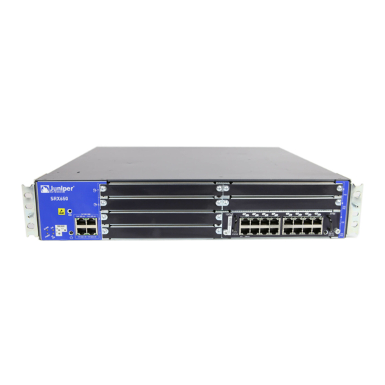
The services gateway provides cost-effective, scalable integration of routing, security, and other mid-range applications for these sites. The SRX650 Services Gateway has a modular 2U chassis that fits a 19-inch rack with a depth of approximately 18.1 inches. It contains a rear-pluggable Services and Routing Engine (SRE) module that provides robust performance for mid-range applications, particularly routing and security services. -
Page 18: Accessing The Srx650 Services Gateway
SRX650 Services Gateway Description on page 3 Documentation Accessing the SRX650 Services Gateway on page 4 SRX650 Services Gateway Software Features and Licenses on page 5 SRX650 Services Gateway Chassis on page 9 Accessing the SRX650 Services Gateway The services gateway runs Junos OS. You can use two user interfaces to monitor, configure,... -
Page 19: Srx650 Services Gateway Software Features And Licenses
Chapter 1: Introduction to the SRX650 Services Gateway SRX650 Services Gateway Software Features and Licenses The services gateway provides the software features listed in Table 3 on page NOTE: Some software features require the purchase of a separate license. For information about features that require a license on this services gateway, see the... - Page 20 SRX650 Services Gateway Hardware Guide Table 3: Software Features and Licenses (continued) Feature Category Feature Encapsulation Ethernet: Media access control (MAC) encapsulation 802.1p tagging Point-to-Point Protocol over Ethernet (PPPoE) Circuit cross-connect (CCC) Translational cross-connect (TCC) Synchronous Point-to-Point Protocol (PPP) Frame Relay High-Level Data Link Control (HDLC) 802.1Q filtering and forwarding...
- Page 21 Chapter 1: Introduction to the SRX650 Services Gateway Table 3: Software Features and Licenses (continued) Feature Category Feature Security IPsec VPN for site-to-site or remote access encrypted tunneling Antivirus filtering, including full antivirus file-based scanning or Express-AV packet-based scanning Antispam and anti-phishing filtering...
- Page 22 Commit scripts Operation scripts Event policies Hot-swappable GPIMs and XPIMs are hot-swappable on the SRX650 Services Gateway. Bypass ports LAN bypass ports are not supported on the SRX Series Services Gateways. Related SRX650 Services Gateway Description on page 3...
-
Page 23: Srx650 Services Gateway Hardware Components And Specifications
SRX650 Services Gateway Gigabit-Backplane Physical Interface Modules on page 23 SRX650 Services Gateway Power over Ethernet Overview on page 25 SRX650 Services Gateway Chassis The SRX650 Services Gateway chassis is a rigid sheet metal structure that houses all the other hardware components. Table 4 on page 9 provides information about the physical specifications for the services gateway. -
Page 24: Srx650 Services Gateway Front Panel
Grounding the SRX650 Services Gateway on page 51 SRX650 Services Gateway General Safety Guidelines and Warnings on page 113 SRX650 Services Gateway Front Panel The front panel of the SRX650 Services Gateway includes the following components: Front panel LEDs Electrostatic discharge (ESD) wrist strap outlet... - Page 25 Chapter 2: SRX650 Services Gateway Hardware Components and Specifications Figure 2: SRX650 Services Gateway Slot Numbers NOTE: The numbers in Figure 1 on page 10 correspond to the numbers in Table 5 on page 11. The information about numbered slots in...
- Page 26 SRX650 Services Gateway Hardware Guide Table 5: SRX650 Services Gateway Front Panel Components (continued) Number Component Location Description FAN LED Left side of the The FAN LED has the following front chassis panel indicator colors: Green and steadily on indicates that the fan is functioning normally.
- Page 27 Chapter 2: SRX650 Services Gateway Hardware Components and Specifications Table 5: SRX650 Services Gateway Front Panel Components (continued) Number Component Location Description 4 fixed Gigabit Ethernet Left side of the The Gigabit Ethernet ports have the ports: front chassis panel...
- Page 28 SRX650 Services Gateway Hardware Guide Table 5: SRX650 Services Gateway Front Panel Components (continued) Number Component Location Description POWER LED Left side of the The POWER LED has the following front chassis panel indicator colors: Green and steadily on indicates...
- Page 29 Chapter 2: SRX650 Services Gateway Hardware Components and Specifications Table 5: SRX650 Services Gateway Front Panel Components (continued) Number Component Location Description SRE/ACE LED 1.1 Left side of the The SRE/ACE 1.1 LED has the front chassis panel following indicator colors: Green and steadily on indicates ACE 1.1 half slot is functioning...
-
Page 30: Srx650 Services Gateway Back Panel
SRX650 Services Gateway Back Panel on page 16 SRX650 Services Gateway Services and Routing Engine 6 on page 20 SRX650 Services Gateway Back Panel The back panel of the SRX650 Services Gateway consists of the following components: Two power supply slots SRE slot... - Page 31 Chapter 2: SRX650 Services Gateway Hardware Components and Specifications Table 6: SRX650 Services Gateway Back Panel Components Number Component Location Description Usage 2 power supply Left side of The power supply Power supplies are slots. Each power back panel provides power to the...
-
Page 32: Srx650 Services Gateway Cooling System
SRX650 Services Gateway Power Supply on page 19 SRX650 Services Gateway Cooling System The fan controller is the cooling system component provided in the SRX650 Services Gateway to keep all components within the acceptable temperature range. The services gateway has a single fan tray that contains four 80 mm fans. -
Page 33: Srx650 Services Gateway Power Supply
Chapter 2: SRX650 Services Gateway Hardware Components and Specifications SRX650 Services Gateway Power Supply The SRX650 Services Gateway uses either one AC or one DC power supply unit (PSU). The services gateway is equipped with one AC power supply (see Figure 4 on page 19). -
Page 34: Srx650 Services Gateway Services And Routing Engine 6
SRX650 Services Gateway Back Panel on page 16 SRX650 Services Gateway Cooling System on page 18 Troubleshooting the Power System on the SRX650 Services Gateway on page 103 SRX650 Services Gateway Services and Routing Engine 6 The Services and Routing Engine (SRE) module provides processing power for security... - Page 35 Chapter 2: SRX650 Services Gateway Hardware Components and Specifications The services gateway must have one SRE installed. CAUTION: The SRE is not hot-swappable. You must power off the services gateway before removing or inserting an SRE. The SRE installs horizontally in the back of the chassis in slots SRE0 or SRE1/SRE1.1. An SRE weighs 3 lb 13.6 oz (1.75 kg).
- Page 36 Off indicates SRE high availability is not enabled. AUX port NOTE: The Auxiliary port is not supported on the SRX650 Services Gateway. CONSOLE port Connects a laptop to the services gateway for CLI management. The port uses an RJ-45 serial connection, is configured as data terminal equipment (DTE), and supports the RS-232 (EIA) standard.
-
Page 37: Srx650 Services Gateway Gigabit-Backplane Physical Interface Modules
Captive screws Secures the SRE to the chassis. Related Removing the SRE from the SRX650 Services Gateway on page 91 Documentation Installing the SRE on the SRX650 Services Gateway on page 92 SRX650 Services Gateway Back Panel on page 16... - Page 38 1 to 4, or the top four slots 5 to 8. Figure 7 on page 24 shows how the slots on the front panel of the SRX650 Services Gateway are numbered. Figure 7: SRX650 Services Gateway Slot Numbers CAUTION: GPIMs are hot-swappable.
-
Page 39: Srx650 Services Gateway Power Over Ethernet Overview
Voice over IP (VoIP) and IP phones and wireless access points. The PoE ports for the SRX650 Services Gateway reside on the individual XPIMs. The SRX650 Services Gateway supports the following XPIMs with PoE: 16-Port Gigabit Ethernet XPIM Copyright ©... - Page 40 SRX Series Services Gateways for the Branch Physical Interface Modules Hardware Guide Related SRX650 Services Gateway Gigabit-Backplane Physical Interface Modules on page 23 Documentation SRX650 Services Gateway Power Supply on page 19 SRX650 Services Gateway Back Panel on page 16...
-
Page 41: Setting Up The Srx650 Services Gateway
Installing the SRX650 Services Gateway on page 41 Connecting the SRX650 Services Gateway on page 47 Grounding, Powering On, and Powering Off the SRX650 Services Gateway on page 51 Establishing Basic Connectivity for the SRX650 Services Gateway on page 55... - Page 42 SRX650 Services Gateway Hardware Guide Copyright © 2014, Juniper Networks, Inc.
-
Page 43: Preparing The Site For Srx650 Services Gateway Installation
Gateway Installation Site Preparation Checklist for the SRX650 Services Gateway on page 29 General Site Installation Guidelines for the SRX650 Services Gateway on page 31 SRX650 Services Gateway Cabinet Requirements on page 32 SRX650 Services Gateway Rack Requirements on page 33... - Page 44 SRX650 Services Gateway Hardware Guide Table 10: Site Preparation Checklist for SRX650 Services Gateway Installation (continued) Performed Item or Task Additional Information Date Notes Calculate the “SRX650 Services power Gateway AC Power consumption Supply Electrical Specifications” on requirements. page 149 “SRX650...
-
Page 45: General Site Installation Guidelines For The Srx650 Services Gateway
Documentation Installation Overview for the SRX650 Services Gateway on page 41 General Site Installation Guidelines for the SRX650 Services Gateway on page 31 General Site Installation Guidelines for the SRX650 Services Gateway The following precautions help you plan an acceptable operating environment for your... -
Page 46: Srx650 Services Gateway Cabinet Requirements
SRX650 Services Gateway Cabinet Airflow Requirements on page 33 SRX650 Services Gateway Cabinet Size and Clearance Requirements You can install the SRX650 Services Gateway in a 19 in (48.3 cm) cabinet as defined in Cabinets, Racks, Panels, and Associated Equipment (document number EIA-310-D) published by the Electronic Industries Alliance ( http://www.ecaus.org/eia/site/index.html... -
Page 47: Srx650 Services Gateway Rack Requirements
Gateway on page 35 SRX650 Services Gateway Cabinet Airflow Requirements When you mount the SRX650 Services Gateway in a cabinet, you must ensure that ventilation through the cabinet is sufficient to prevent overheating. Consider the following when planning for chassis cooling: Ensure that the cool air supply you provide through the cabinet can adequately dissipate the thermal output of the services gateway. -
Page 48: Holes
Connecting the SRX650 Services Gateway to the Building Structure on page 34 Connecting the SRX650 Services Gateway to the Building Structure Always secure the rack in which you are installing the SRX650 Services Gateway to the structure of the building. If your geographical area is subject to earthquakes, bolt the rack to the floor. -
Page 49: Clearance Requirements For Airflow And Hardware Maintenance Of The Srx650 Services Gateway
Clearance Requirements for Airflow and Hardware Maintenance of the SRX650 Services Gateway When planning the installation site for the SRX650 Services Gateway, you need to allow sufficient clearance around the rack. When planning the installation site for the services gateway, consider the following: For the cooling system to function properly, the airflow around the chassis must be unrestricted. -
Page 50: Srx650 Services Gateway Power Requirements
Site Preparation Checklist for the SRX650 Services Gateway on page 29 SRX650 Services Gateway Rack Size and Strength Requirements on page 33 General Site Installation Guidelines for the SRX650 Services Gateway on page 31 SRX650 Services Gateway Power Requirements The electrical and power requirements for the SRX650 Services Gateway provide information about the factors you must consider while planning the electrical wiring and power availability at your site. -
Page 51: Unpacking The Srx650 Services Gateway
Installation Overview for the SRX650 Services Gateway on page 41 Unpacking the SRX650 Services Gateway The SRX650 Services Gateway is shipped in a cardboard carton and secured with foam packing material. The carton also contains an accessory box and quick start instructions. -
Page 52: Verifying Parts Received With The Srx650 Services Gateway
Component Quantity 2U SRX650 Services Gateway chassis with 8 GPIM slots, 1 SRE slot, and 1 multi-use processor slot; 2 power supply slots; 1 fan tray with fans; and 4 10/100/1000 base-T ports. Includes blank covers for GPIM (8 covers for GPIM slots), SRE, multi-use processor, and power supply slots. - Page 53 2 GB DRAM CompactFlash card 645 W DC power supply with PoE support Related Required Tools and Parts for Unpacking the SRX650 Services Gateway on page 37 Documentation Preparing the SRX650 Services Gateway for Rack-Mount Installation on page 42 Unpacking the SRX650 Services Gateway on page 37...
- Page 54 SRX650 Services Gateway Hardware Guide Copyright © 2014, Juniper Networks, Inc.
-
Page 55: Installing The Srx650 Services Gateway
Installation Overview for the SRX650 Services Gateway on page 41 SRX650 Services Gateway Safety Requirements, Warnings, and Guidelines on page 41 Required Tools and Parts for Installing the SRX650 Services Gateway on page 42 Preparing the SRX650 Services Gateway for Rack-Mount Installation on page 42... -
Page 56: Required Tools And Parts For Installing The Srx650 Services Gateway
Documentation SRX650 Services Gateway Electrical Wiring Guidelines on page 147 Required Tools and Parts for Installing the SRX650 Services Gateway on page 42 Preparing the SRX650 Services Gateway for Rack-Mount Installation on page 42 General Site Installation Guidelines for the SRX650 Services Gateway on page 31... -
Page 57: Installing The Srx650 Services Gateway In A Rack
Installation Overview for the SRX650 Services Gateway on page 41 Installing the SRX650 Services Gateway in a Rack You can front-mount the SRX650 Services Gateway in a rack. The mounting brackets are an optional accessory. Many types of racks are acceptable, including four-post (telco) racks, enclosed cabinets, and open-frame racks. -
Page 58: Scheme
Grounding the SRX650 Services Gateway on page 51 SRX650 Services Gateway Software Configuration Overview on page 55 SRX650 Services Gateway Boot Devices and Dual-Root Partitioning Scheme The SRX650 Services Gateway can boot from the following storage media (in order of priority): Internal CompactFlash card (default; always present) - Page 59 When the SRX650 Services Gateway powers up, it tries to boot the Junos OS from the default storage media. If the device fails to boot from the default storage media, it tries to boot from the alternate storage media.
- Page 60 SRX650 Services Gateway Hardware Guide Copyright © 2014, Juniper Networks, Inc.
-
Page 61: Connecting The Srx650 Services Gateway
Do not mix AC and DC power supplies within the same services gateway. Damage to the device might occur. The 645 W AC power supply with PoE support is available for the SRX650 Services Gateway. You connect AC power to the services gateway by attaching the power cord from the AC power source to the AC appliance inlet located on the power supply. -
Page 62: Srx650 Services Gateway
CAUTION: Do not mix AC and DC power supplies within the same services gateway. Damage to the device might occur. The 645 W DC power supply with PoE support is available for the SRX650 Services Gateway. WARNING: Before performing the following procedure, ensure that power is removed from the DC circuit. - Page 63 Chapter 6: Connecting the SRX650 Services Gateway You connect DC power to the device by attaching power cables from the external DC power sources to the terminal studs on the power supply faceplate. You must provide the power cables (the cable lugs are supplied with the services gateway).
- Page 64 Place excess cable out of the way in neatly coiled loops. Use fasteners to maintain the shape of cable loops. Related Connecting the SRX650 Services Gateway to the AC Power Supply on page 47 Documentation Connecting the SRX650 Services Gateway to the DC Power Supply on page 48...
-
Page 65: Grounding The Srx650 Services Gateway
CHAPTER 7 Grounding, Powering On, and Powering Off the SRX650 Services Gateway Required Tools and Parts for Grounding, Powering On, and Powering Off the SRX650 Services Gateway on page 51 Grounding the SRX650 Services Gateway on page 51 Powering On and Powering Off the SRX650 Services Gateway on page 52... -
Page 66: Powering On And Powering Off The Srx650 Services Gateway
Powering On the SRX650 Services Gateway on page 52 Documentation Powering Off the SRX650 Services Gateway on page 53 Required Tools and Parts for Grounding, Powering On, and Powering Off the SRX650 Services Gateway on page 51 SRX650 Services Gateway General Safety Guidelines and Warnings on page 113... -
Page 67: Powering Off The Srx650 Services Gateway
Chapter 7: Grounding, Powering On, and Powering Off the SRX650 Services Gateway b. Using DC power supply—Connect DC power cables to the terminals and the other ends to an external DC power source. If you have two DC power sources... -
Page 68: Resetting The Srx650 Services Gateway
To press this button, insert a small probe (such as a straightened paper clip) into the pinhole on the SRE on the back panel of the chassis (see “SRX650 Services Gateway Services and Routing Engine 6” on page 20). For example, if someone inadvertently commits a configuration that denies management access to a services gateway, you can delete the invalid configuration and replace it with a rescue configuration by pressing the RESET CONFIG button. -
Page 69: Establishing Basic Connectivity For The Srx650 Services Gateway
SRX650 Services Gateway Basic Connectivity on page 55 Connecting to the SRX650 Services Gateway on page 61 Configuring Basic Settings for the SRX650 Services Gateway with the CLI or the J-Web Interface on page 68 Displaying Basic Connectivity Configurations for the SRX650 Services... -
Page 70: Connecting To The Srx650 Services Gateway Setup Wizard
Documentation Connecting to the SRX650 Services Gateway Setup Wizard on page 61 Connecting to the SRX650 Services Gateway from the CLI Locally on page 63 Connecting to the SRX650 Services Gateway from the CLI Remotely on page 65 SRX650 Services Gateway Basic Settings Table 15 on page 57 provides information on basic connectivity settings. - Page 71 Chapter 8: Establishing Basic Connectivity for the SRX650 Services Gateway Table 15: Services Gateway Basic Connectivity Settings Details Element Description Settings Device The hostname defines the network or subnetwork to The hostname refers to the specific machine, while identification which your services gateway belongs.
- Page 72 Documentation Connecting to the SRX650 Services Gateway Setup Wizard on page 61 Connecting to the SRX650 Services Gateway from the CLI Locally on page 63 Connecting to the SRX650 Services Gateway from the CLI Remotely on page 65 Built-In Ethernet Ports for the SRX650 Services Gateway...
- Page 73 Chapter 8: Establishing Basic Connectivity for the SRX650 Services Gateway Table 16: Default Interface Configuration for the Services Gateway (continued) Interface Security Zone DHCP State Address (if used) Trust Server ge-0/0/1 192.168.1.1/24 NOTE: If chassis clustering is enabled, use this port as the...
- Page 74 SRX650 Services Gateway Software Configuration Overview on page 55 SRX650 Services Gateway Secure CLI Access Overview Telnet allows you to connect to the SRX650 Services Gateway and access the CLI to execute commands from a remote system. Telnet connections are not encrypted and therefore can be intercepted.
-
Page 75: Connecting The Modem At The Srx650 Services Gateway End
Connecting the CLI at the User End for the SRX650 Services Gateway on page 67 Connecting to the SRX650 Services Gateway Setup Wizard If you plan to use the setup wizard to configure the SRX650 Services Gateway, you must connect through the built-in Ethernet port 0/1 as shown in... -
Page 76: Gateway
SRX650 Services Gateway Hardware Guide Figure 12: Connecting to the Ethernet Port on the SRX650 Services Gateway Ethernet port Ethernet cable To enable communication between the management device and the services gateway, port 0/1 is preconfigured with the IP address 192.168.1.1 and uses DHCP to assign an IP address in the 192.168.1.0/24 network to any connected device. - Page 77 Connecting to the SRX650 Services Gateway from the CLI Remotely on page 65 Connecting to the SRX650 Services Gateway from the CLI Locally If you plan to use the CLI to configure the SRX650 Services Gateway, you must connect through the console port, as shown in Figure 14 on page Copyright ©...
- Page 78 SRX650 Services Gateway Hardware Guide Figure 14: Connecting to the Console Port on the SRX650 Services Gateway Serial port Adapter Console port Ethernet cable NOTE: Figure 14 on page 64 shows a connection to a local management device. A remote connection to the services gateway through a modem requires the cable and connector shown (RJ-45 to a DB-9 serial port adapter), along with an adapter for your modem, which you must purchase separately.
- Page 79 Connecting to the SRX650 Services Gateway from the CLI Remotely on page 65 Connecting to the SRX650 Services Gateway from the CLI Remotely You can connect an SRX650 Services Gateway to the CLI from a remote location through two dial-up modems:...
- Page 80 Connecting to the SRX650 Services Gateway from the CLI Remotely on page 65 Documentation Connecting the Modem to the Console Port on the SRX650 Services Gateway on page 67 Connecting the CLI at the User End for the SRX650 Services Gateway on page 67 Copyright © 2014, Juniper Networks, Inc.
-
Page 81: Connecting The Cli At The User End For The Srx650 Services Gateway
Documentation Connecting the Modem at the SRX650 Services Gateway End on page 65 Connecting the CLI at the User End for the SRX650 Services Gateway on page 67 Connecting the CLI at the User End for the SRX650 Services Gateway... -
Page 82: J-Web Interface
Connecting the Modem to the Console Port on the SRX650 Services Gateway on page 67 Configuring Basic Settings for the SRX650 Services Gateway with the CLI or the J-Web Interface This topic describes how to configure basic settings for your services gateway using either the CLI or the J-Web setup wizard. - Page 83 Chapter 8: Establishing Basic Connectivity for the SRX650 Services Gateway In a typical network, the services gateway has the basic settings listed in Table 22 on page 69. Determine the values to set on the services gateway in your network.
- Page 84 SRX650 Services Gateway Hardware Guide Table 23: Configuring Basic Settings (continued) Required or Using the J-Web Setup Task Optional Wizard Using the CLI Define the root Required On the Configure System: Specify the root password for the Identification page, type password.
- Page 85 Chapter 8: Establishing Basic Connectivity for the SRX650 Services Gateway Table 23: Configuring Basic Settings (continued) Required or Using the J-Web Setup Task Optional Wizard Using the CLI Configure Optional From the Configure Interfaces Specify an interface interfaces other page, click Add, Edit, or other than a VLAN than VLANs.
-
Page 86: Displaying Basic Connectivity Configurations For The Srx650 Services
72 Displaying Basic Connectivity Configurations for the SRX650 Services Gateway To verify that the SRX650 Services Gateway has the settings you configured, you should display the basic connectivity configurations. Because the basic connectivity settings appear in different places in the configuration hierarchy, displaying the entire configuration at once makes viewing the settings easier. -
Page 87: Gateway
Documentation Performing Initial Software Configuration on the SRX650 Services Gateway Using the Setup Wizard Configuring Basic Settings for the SRX650 Services Gateway with the CLI or the J-Web Interface on page 68 SRX650 Services Gateway Secure Web Access Overview You can manage a services gateway remotely through the J-Web interface. To communicate with the services gateway, the J-Web interface uses Hypertext Transfer Protocol (HTTP). - Page 88 SRX650 Services Gateway Software Configuration Overview on page 55 Documentation Performing Initial Software Configuration on the SRX650 Services Gateway Using the Setup Wizard Configuring Basic Settings for the SRX650 Services Gateway with the CLI or the J-Web Interface on page 68 Copyright © 2014, Juniper Networks, Inc.
-
Page 89: Part 3 Srx650 Services Gateway Hardware Maintenance
SRX650 Services Gateway Hardware Maintenance, Replacement, and Troubleshooting Procedures Replacing Hardware Components on the SRX650 Services Gateway on page 77 Maintaining SRX650 Services Gateway Hardware Components on page 95 Troubleshooting the SRX650 Services Gateway on page 97 Copyright © 2014, Juniper Networks, Inc. - Page 90 SRX650 Services Gateway Hardware Guide Copyright © 2014, Juniper Networks, Inc.
-
Page 91: Replacing Hardware Components On The Srx650 Services Gateway
Replacing the Fan Tray on the SRX650 Services Gateway on page 78 Replacing the Air Filter on the SRX650 Services Gateway on page 80 Replacing the AC Power Supply on the SRX650 Services Gateway on page 84 Replacing a DC Power Supply on the SRX650 Services Gateway on page 87... -
Page 92: Replacing The Fan Tray On The Srx650 Services Gateway
Replacing the Fan Tray on the SRX650 Services Gateway The SRX650 Services Gateway has one fan tray that installs vertically in the rear of the chassis on the right side. The fan tray contains four 80 mm fans and weighs 1 lb, 13.4 oz (.833 kg). -
Page 93: Installing The Fan Tray On The Srx650 Services Gateway
Figure 16: Removing the Fan Tray from the Services Gateway Related Installing the Fan Tray on the SRX650 Services Gateway on page 79 Documentation Required Tools and Parts for Replacing Hardware Components on the SRX650 Services... -
Page 94: Replacing The Air Filter On The Srx650 Services Gateway
Replacing the Air Filter on the SRX650 Services Gateway The SRX650 Services Gateway has provision for one air filter that installs vertically in the rear of the chassis on the right side. The air filter weighs 2.2 oz (62.37 g) and is hot-swappable. - Page 95 Chapter 9: Replacing Hardware Components on the SRX650 Services Gateway A single handle with two screws holds both the fan tray and air filter on the back of the services gateway. NOTE: You can replace the air filter while the services gateway is running.
-
Page 96: Installing The Air Filter On The Srx650 Services Gateway
SRX650 Services Gateway Hardware Guide Figure 19: Removing the Air Filter Related Installing the Air Filter on the SRX650 Services Gateway on page 82 Documentation Required Tools and Parts for Replacing Hardware Components on the SRX650 Services Gateway on page 77... - Page 97 Figure 21 on page 83). Figure 21: Tightening Captive Screws Related Removing the Air Filter from the SRX650 Services Gateway on page 80 Documentation Required Tools and Parts for Replacing Hardware Components on the SRX650 Services Gateway on page 77...
-
Page 98: Replacing The Ac Power Supply On The Srx650 Services Gateway
If you remove a power supply, you must install a replacement power supply or a blank panel shortly after the removal. To replace an AC power supply on the SRX650 Services Gateway, use the following sections:... -
Page 99: Installing An Ac Power Supply On The Srx650 Services Gateway
Figure 22: Removing an AC Power Supply from the SRX650 Services Gateway Related Installing an AC Power Supply on the SRX650 Services Gateway on page 85 Documentation Required Tools and Parts for Replacing Hardware Components on the SRX650 Services Gateway on page 77... - Page 100 Figure 23: Installing an AC Power Supply on the SRX650 Services Gateway Related Removing an AC Power Supply from the SRX650 Services Gateway on page 84 Documentation Connecting an AC Power Cord to the SRX650 Services Gateway on page 87...
-
Page 101: Connecting An Ac Power Cord To The Srx650 Services Gateway
If you remove a power supply, you must install a replacement power supply or a blank panel shortly after the removal. To replace a DC power supply on the SRX650 Services Gateway, use the following sections:... - Page 102 Push the tab on the left edge of the power supply to the right. Pull the power supply straight out of the chassis. Figure 24: Removing a DC Power Supply from the SRX650 Services Gateway Copyright © 2014, Juniper Networks, Inc.
-
Page 103: Installing A Dc Power Supply On The Srx650 Services Gateway
Gateway on page 77 Installing a DC Power Supply on the SRX650 Services Gateway on page 89 Removing a DC Power Supply Cable from the SRX650 Services Gateway on page 91 Installing a DC Power Supply on the SRX650 Services Gateway... -
Page 104: Gateway
Required Tools and Parts for Replacing Hardware Components on the SRX650 Services Documentation Gateway on page 77 Removing a DC Power Supply from the SRX650 Services Gateway on page 87 Removing a DC Power Supply Cable from the SRX650 Services Gateway on page 91 Copyright © 2014, Juniper Networks, Inc. -
Page 105: Replacing The Sre On The Srx650 Services Gateway
Installing a DC Power Supply on the SRX650 Services Gateway on page 89 Replacing the SRE on the SRX650 Services Gateway You can replace the Services and Routing Engine (SRE) on the SRX650 Services Gateway. The following sections describe how to remove and install the SRE:... -
Page 106: Installing The Sre On The Srx650 Services Gateway
SRX650 Services Gateway Back Panel on page 16 Documentation Installing the SRE on the SRX650 Services Gateway on page 92 SRX650 Services Gateway Services and Routing Engine 6 on page 20 Powering Off the SRX650 Services Gateway on page 53... - Page 107 SRX650 Services Gateway Back Panel on page 16 Documentation Removing the SRE from the SRX650 Services Gateway on page 91 SRX650 Services Gateway Services and Routing Engine 6 on page 20 Powering On the SRX650 Services Gateway on page 52...
- Page 108 SRX650 Services Gateway Hardware Guide Copyright © 2014, Juniper Networks, Inc.
-
Page 109: Maintaining Srx650 Services Gateway Hardware Components
CHAPTER 10 Maintaining SRX650 Services Gateway Hardware Components Required Tools and Parts for Maintaining the SRX650 Services Gateway Hardware Components on page 95 Routine Maintenance Procedures for the SRX650 Services Gateway on page 95 Maintaining the SRX650 Services Gateway Cooling System Components on page 96... -
Page 110: Maintaining The Srx650 Services Gateway Cooling System Components
Check the status LEDs on the front panel of the services gateway, the back panel, and on the Services and Routing Engine (SRE) you are using. Related Required Tools and Parts for Maintaining the SRX650 Services Gateway Hardware Documentation Components on page 95... -
Page 111: Chapter 11 Troubleshooting The Srx650 Services Gateway
Inaccessible on page 106 Troubleshooting Hardware Components on the SRX650 Services Gateway Troubleshooting with the CLI on the SRX650 Services Gateway on page 97 Troubleshooting with LEDs on the SRX650 Services Gateway on page 98 Troubleshooting with Chassis and Interface Alarm Messages on the SRX650 Services... - Page 112 SRX650 Services Gateway Hardware Guide Troubleshooting with LEDs on the SRX650 Services Gateway The LEDs available on the services gateway display the status of various components. Table 25 on page 98describes the LEDs on the chassis. To view LED information on the Services and Routing Engine (SRE), see “SRX650 Services Gateway Services and Routing...
-
Page 113: Troubleshooting The Srx650 Services Gateway
Chapter 11: Troubleshooting the SRX650 Services Gateway Table 25: Component LEDs on the Services Gateway Chassis (continued) Location Usage HA SYS Left side of the front chassis The High Availability (HA SYS) LED panel has the following indicator colors: Green and steadily on indicates all configured chassis cluster links are available. -
Page 114: Troubleshooting With Chassis And Interface Alarm Messages On The Srx650
Related SRX650 Services Gateway Front Panel on page 10 Documentation SRX650 Services Gateway Back Panel on page 16 Troubleshooting with Chassis and Interface Alarm Messages on the SRX650 Services Gateway on page 101 Copyright © 2014, Juniper Networks, Inc. -
Page 115: Using The Reset Config Button On The Srx650 Services Gateway
Chapter 11: Troubleshooting the SRX650 Services Gateway Troubleshooting the Power System on the SRX650 Services Gateway on page 103 Using the RESET CONFIG Button on the SRX650 Services Gateway on page 106 Changing the RESET CONFIG Button Behavior on the SRX650 Services Gateway on... - Page 116 SRX650 Services Gateway Hardware Guide Table 26: Alarms for Services Gateway Chassis Components Component Alarm Conditions Action Alarm Severity Boot media The services gateway If the internal flash fails at Yellow (minor) boots from an startup, the services alternate boot device.
- Page 117 SRX650 Services Gateway Back Panel on page 16 Troubleshooting the Power System on the SRX650 Services Gateway on page 103 Using the RESET CONFIG Button on the SRX650 Services Gateway on page 106 Changing the RESET CONFIG Button Behavior on the SRX650 Services Gateway on...
- Page 118 SRX650 Services Gateway Hardware Guide Table 27: POWER LED Description (continued) Possible Cause and Corrective LED Status LED State Meaning Action Indicates that the If a red alarm condition occurs, services gateway is issue the show chassis alarms not receiving power.
- Page 119 The DC input power provided to the power supply is outside of tolerance. Unlit The power supply is not receiving input power. Related Troubleshooting with the CLI on the SRX650 Services Gateway on page 97 Documentation Copyright © 2014, Juniper Networks, Inc.
-
Page 120: Gateway
Troubleshooting with Chassis and Interface Alarm Messages on the SRX650 Services Gateway on page 101 Removing an AC Power Supply from the SRX650 Services Gateway on page 84 SRX650 Services Gateway Front Panel on page 10 SRX650 Services Gateway Back Panel on page 16 Resetting the Configuration File When the SRX650 Services Gateway Is Inaccessible You can use the SRX650 Services Gateway’s RESET CONFIG button to restore the... - Page 121 Documentation Troubleshooting with the CLI on the SRX650 Services Gateway on page 97 Using the RESET CONFIG Button on the SRX650 Services Gateway on page 106 SRX650 Services Gateway Front Panel on page 10 Troubleshooting the Power System on the SRX650 Services Gateway on page 103...
- Page 122 SRX650 Services Gateway Hardware Guide Copyright © 2014, Juniper Networks, Inc.
-
Page 123: Appendixes
SRX650 Services Gateway Environmental Specifications on page 145 SRX650 Services Gateway Power Guidelines, Requirements, and Specifications on page 147 Contacting Customer Support and Returning the SRX650 Services Gateway Hardware on page 153 SRX650 Services Gateway Interface Cable Specifications and Connector Pinouts on page 159 Copyright ©... - Page 124 SRX650 Services Gateway Hardware Guide Copyright © 2014, Juniper Networks, Inc.
- Page 125 Equipment on page 117 SRX650 Services Gateway Installation Safety Guidelines and Warnings on page 118 SRX650 Services Gateway Laser and LED Safety Guidelines and Warnings on page 123 SRX650 Services Gateway Maintenance and Operational Safety Guidelines and Warnings on page 126...
- Page 126 SRX650 Services Gateway Hardware Guide WARNING: This symbol is used with laser warnings. Unterminated optical connectors can emit invisible laser radiation. Focusing your eye directly on a laser source—even a low-power laser—could permanently damage the eye. WARNING: This symbol means danger. You are in a situation that could cause bodily injury.
-
Page 127: Appendix A Safety And Regulatory Compliance Information
Related SRX650 Services Gateway General Safety Guidelines and Warnings on page 113 Documentation Preventing Electrostatic Discharge Damage to the SRX650 Services Gateway on... -
Page 128: Additional Srx650 Services Gateway Warnings
Avoid touching uninsulated electrical wires or terminals that have not been disconnected from their power source. Such an action could cause electrical shock. Related SRX650 Services Gateway Definition of Safety Warning Levels on page 111 Documentation Preventing Electrostatic Discharge Damage to the SRX650 Services Gateway on... -
Page 129: Restricted Access Area Warning
Aviso Esta unidade foi concebida para instalação em áreas de acesso restrito. Uma área de acesso restrito é uma área à qual apenas tem acesso o pessoal de serviço autorizado, que possua uma ferramenta, chave e fechadura Copyright © 2014, Juniper Networks, Inc. -
Page 130: Preventing Electrostatic Discharge Damage To The Srx650 Services
Related SRX650 Services Gateway General Safety Guidelines and Warnings on page 113 Documentation Qualified Personnel Warning on page 114 Preventing Electrostatic Discharge Damage to the SRX650 Services Gateway Many services gateway hardware components are sensitive to damage from static electricity. -
Page 131: Srx650 Services Gateway Fire Safety Requirements And Fire Suppression
Appendix A: Safety and Regulatory Compliance Information Figure 28: Placing a Component into an Electrostatic Bag Related SRX650 Services Gateway Definition of Safety Warning Levels on page 111 Documentation SRX650 Services Gateway Fire Safety Requirements and Fire Suppression Equipment on page 117... -
Page 132: Srx650 Services Gateway Installation Safety Guidelines And Warnings
To keep warranties effective, do not use a dry chemical fire extinguisher to control a fire at or near a Juniper Networks services gateway. If a dry chemical fire extinguisher is used, the unit is no longer eligible for coverage under a service agreement. -
Page 133: Rack-Mounting Requirements And Warnings
Varning! Läs installationsanvisningarna innan du kopplar systemet till dess strömförsörjningsenhet. Related SRX650 Services Gateway General Safety Guidelines and Warnings on page 113 Documentation Rack-Mounting Requirements and Warnings on page 119 SRX650 Services Gateway Fire Safety Requirements and Fire Suppression Equipment... - Page 134 Les directives ci-dessous sont destinées à assurer la protection du personnel: Le rack sur lequel est monté le Juniper Networks services gateway doit être fixé à la structure du bâtiment. Si cette unité constitue la seule unité montée en casier, elle doit être placée dans le bas.
- Page 135 Le seguenti direttive vengono fornite per garantire la sicurezza personale: Il Juniper Networks services gateway deve essere installato in un telaio, il quale deve essere fissato alla struttura dell'edificio. Questa unità deve venire montata sul fondo del supporto, se si tratta dell'unica unità...
- Page 136 Om ställningen är försedd med stabiliseringsdon skall dessa monteras fast innan enheten installeras eller underhålls på ställningen. Related SRX650 Services Gateway General Safety Guidelines and Warnings on page 113 Documentation Installation Instructions Warning on page 118 SRX650 Services Gateway Fire Safety Requirements and Fire Suppression Equipment on page 117 Copyright ©...
-
Page 137: Srx650 Services Gateway Laser And Led Safety Guidelines And Warnings
Related SRX650 Services Gateway General Safety Guidelines and Warnings on page 113 Documentation Class 1 Laser Warning on page 123 Class 1 LED Product Warning on page 124... -
Page 138: Class 1 Led Product Warning
Aviso Produto laser de classe 1. ¡Atención! Producto láser Clase I. Varning! Laserprodukt av klass 1. Related SRX650 Services Gateway General Safety Guidelines and Warnings on page 113 Documentation General Laser Safety Guidelines on page 123 Class 1 LED Product Warning on page 124... -
Page 139: Laser Beam Warning
Varning! Rikta inte blicken in mot strålen och titta inte direkt på den genom optiska instrument. Related SRX650 Services Gateway General Safety Guidelines and Warnings on page 113 Documentation General Laser Safety Guidelines on page 123 Class 1 Laser Warning on page 123... -
Page 140: Srx650 Services Gateway Maintenance And Operational Safety Guidelines And Warnings
öppningar. Related SRX650 Services Gateway General Safety Guidelines and Warnings on page 113 Documentation General Laser Safety Guidelines on page 123 Class 1 Laser Warning on page 123... -
Page 141: Operating Temperature Warning
Desechar las baterías gastadas según las instrucciones del fabricante. Varning! Explosionsfara vid felaktigt batteribyte. Ersätt endast batteriet med samma batterityp som rekommenderas av tillverkaren eller motsvarande. Följ tillverkarens anvisningar vid kassering av använda batterier. Copyright © 2014, Juniper Networks, Inc. - Page 142 SRX650 Services Gateway Hardware Guide Related SRX650 Services Gateway General Safety Guidelines and Warnings on page 113 Documentation Jewelry Removal Warning on page 128 Lightning Activity Warning on page 129 Operating Temperature Warning on page 130 Product Disposal Warning on page 131...
- Page 143 Related SRX650 Services Gateway General Safety Guidelines and Warnings on page 113 Documentation Battery-Handling Warning on page 127 Lightning Activity Warning on page 129...
- Page 144 Varning! Vid åska skall du aldrig utföra arbete på systemet eller ansluta eller koppla loss kablar. Related SRX650 Services Gateway General Safety Guidelines and Warnings on page 113 Documentation Battery-Handling Warning on page 127 Jewelry Removal Warning on page 128...
-
Page 145: Product Disposal Warning
15,2 cm omkring ventilationsöppningarna. Related SRX650 Services Gateway General Safety Guidelines and Warnings on page 113 Documentation Battery-Handling Warning on page 127 Lightning Activity Warning on page 129... -
Page 146: Srx650 Services Gateway Electrical Safety Guidelines And Warnings
Varning! Slutlig kassering av denna produkt bör skötas i enlighet med landets alla lagar och föreskrifter. Related SRX650 Services Gateway General Safety Guidelines and Warnings on page 113 Documentation Battery-Handling Warning on page 127 Lightning Activity Warning on page 129... -
Page 147: General Electrical Safety Guidelines And Warnings
Appendix A: Safety and Regulatory Compliance Information Related SRX650 Services Gateway General Safety Guidelines and Warnings on page 113 Documentation General Electrical Safety Guidelines and Warnings on page 133 AC Power Electrical Safety Guidelines on page 134 SRX650 Services Gateway Power Requirements on page 36... - Page 148 The attached power cable is only for this product. Do not use the cable for another product. Related SRX650 Services Gateway General Safety Guidelines and Warnings on page 113 Documentation In Case of Electrical Accident on page 132 General Electrical Safety Guidelines and Warnings on page 133...
-
Page 149: Dc Power Electrical Safety Guidelines
Appendix A: Safety and Regulatory Compliance Information SRX650 Services Gateway Power Requirements on page 36 Grounding the SRX650 Services Gateway on page 51 DC Power Electrical Safety Guidelines When working with DC-powered equipment, observe the following guidelines and warnings: DC Power Electrical Safety Guidelines... - Page 150 SRX650 Services Gateway Hardware Guide For personal safety, connect the green and yellow wire to safety (earth) ground at both the services gateway and the supply side of the DC wiring. The marked input voltage of –48 VDC for a DC-powered services gateway is the nominal voltage associated with the battery circuit, and any higher voltages are only to be associated with float voltages for the charging function.
- Page 151 Attention Lors de l'installation de l'appareil, la mise à la terre doit toujours être connectée en premier et déconnectée en dernier. Warnung Der Erdanschluß muß bei der Installation der Einheit immer zuerst hergestellt und zuletzt abgetrennt werden. Copyright © 2014, Juniper Networks, Inc.
- Page 152 SRX650 Services Gateway Hardware Guide Avvertenza In fase di installazione dell'unità, eseguire sempre per primo il collegamento a massa e disconnetterlo per ultimo. Advarsel Når enheten installeres, må jordledningen alltid tilkobles først og frakobles sist. Aviso Ao instalar a unidade, a ligação à terra deverá ser sempre a primeira a ser ligada, e a última a ser desligada.
- Page 153 Varoitus Jos säikeellinen johdin on tarpeen, käytä hyväksyttyä johdinliitäntää, esimerkiksi suljettua silmukkaa tai kourumaista liitäntää, jossa on ylöspäin käännetyt kiinnityskorvat. Tällaisten liitäntöjen tulee olla kooltaan johtimiin sopivia ja niiden tulee puristaa yhteen sekä eristeen että johdinosan. Copyright © 2014, Juniper Networks, Inc.
- Page 154 Storleken på dessa kontakter måste vara avpassad till ledningarna och måste kunna hålla både isoleringen och ledaren fastklämda. Related SRX650 Services Gateway General Safety Guidelines and Warnings on page 113 Documentation In Case of Electrical Accident on page 132 General Electrical Safety Guidelines and Warnings on page 133...
-
Page 155: Srx650 Services Gateway Agency Approvals
EN-61000-4-6 (2007) Immunity to Conducted Disturbances EN-61000-4-11 (2004) Voltage Dips and Sags Related SRX650 Services Gateway General Safety Guidelines and Warnings on page 113 Documentation SRX650 Services Gateway Acoustic Noise Compliance Statements on page 144 Copyright © 2014, Juniper Networks, Inc. -
Page 156: Srx650 Services Gateway Compliance Statements For Emc Requirements
This Class A digital apparatus complies with Canadian ICES-003. Cet appareil numérique de la classe A est conforme à la norme NMB-003 du Canada. Related SRX650 Services Gateway General Safety Guidelines and Warnings on page 113 Documentation European Community on page 142... -
Page 157: Israel
This product is Class A. In residential environments, the product may cause radio interference, and in such a situation, the user may be required to take adequate measures. Related SRX650 Services Gateway General Safety Guidelines and Warnings on page 113 Documentation Canada on page 142... -
Page 158: Srx650 Services Gateway Compliance Statements For Environmental Requirements
Related SRX650 Services Gateway General Safety Guidelines and Warnings on page 113 Documentation Canada on page 142... -
Page 159: Srx650 Services Gateway Environmental Specifications
APPENDIX B SRX650 Services Gateway Environmental Specifications SRX650 Services Gateway Environmental Specifications on page 145 SRX650 Services Gateway Environmental Specifications Table 29 on page 145 provides the required environmental conditions for normal SRX650 Services Gateway operations. In addition, the site must be as dust-free as possible because dust can clog air intake vents and filters, reducing the efficiency of the cooling system. - Page 160 Articles 110–16, 110–17, and 110–18 of the National Electrical Code, ANSI/NFPA 70. Related SRX650 Services Gateway General Safety Guidelines and Warnings on page 113 Documentation Routine Maintenance Procedures for the SRX650 Services Gateway on page 95...
-
Page 161: Srx650 Services Gateway Power Guidelines, Requirements, And Specifications
Guidelines, Requirements, and Specifications SRX650 Services Gateway Electrical Wiring Guidelines on page 147 SRX650 Services Gateway Power Specifications and Requirements on page 148 SRX650 Services Gateway Grounding Specifications on page 152 SRX650 Services Gateway Electrical Wiring Guidelines Table 30 on page 147 describes the factors you must consider while planning the electrical wiring for the SRX650 Services Gateway at your site. -
Page 162: Srx650 Services Gateway Power Specifications And Requirements
The addition of primary protectors is not sufficient protection to connect these interfaces metallically to OSP wiring. Related General Site Installation Guidelines for the SRX650 Services Gateway on page 31 Documentation Maintaining the SRX650 Services Gateway Power Supply on page 96... -
Page 163: Srx650 Services Gateway Ac Power Supply Electrical Specifications
SRX650 Services Gateway DC Power Supply Electrical Specifications on page 150 SRX650 Services Gateway DC Power Cable Specifications on page 151 SRX650 Services Gateway AC Power Supply Electrical Specifications The AC power supply electrical specifications for the SRX650 Services Gateway are listed in Table 31 on page 149. - Page 164 SRX650 Services Gateway Electrical Wiring Guidelines on page 147 Site Preparation Checklist for the SRX650 Services Gateway on page 29 SRX650 Services Gateway DC Power Supply Electrical Specifications The DC power supply electrical specifications for the SRX650 Services Gateway are listed in Table 33 on page 150.
- Page 165 Related SRX650 Services Gateway Power Supply on page 19 Documentation Clearance Requirements for Airflow and Hardware Maintenance of the SRX650 Services Gateway on page 35 SRX650 Services Gateway Electrical Wiring Guidelines on page 147 Site Preparation Checklist for the SRX650 Services Gateway on page 29...
-
Page 166: Srx650 Services Gateway Grounding Specifications
Grounding the SRX650 Services Gateway on page 51 Documentation Connecting the SRX650 Services Gateway to the AC Power Supply on page 47 Powering On the SRX650 Services Gateway on page 52 Powering Off the SRX650 Services Gateway on page 53... -
Page 167: Contacting Customer Support And Returning The Srx650 Services
Packing the SRX650 Services Gateway or a Component for Shipment on page 156 Return Procedure for the SRX650 Services Gateway To return an SRX650 Services Gateway or component to Juniper Networks for repair or replacement: Determine the part number and serial number of the services gateway or component. -
Page 168: Locating The Srx650 Services Gateway Chassis Serial Number And Agency
Before contacting Juniper Networks to request a Return Materials Authorization (RMA), you must find the serial number on the SRX650 Services Gateway or component. To list all of the SRX650 Services Gateway components and their serial numbers, enter the following command-line interface (CLI) command: user@host>... -
Page 169: Srx650 Services Gateway
Appendix D: Contacting Customer Support and Returning the SRX650 Services Gateway Hardware Locating the SRX650 Services Gateway Chassis Serial Number and Agency Labels The SRX650 Services Gateway serial number is located on the bottom of the device on the compliance/agency label. -
Page 170: Packing The Srx650 Services Gateway Or A Component For Shipment
Contacting Customer Support Once you have located the serial numbers of the device or component, you can return the device or component for repair or replacement. For this, you need to contact Juniper Networks Technical Assistance Center (JTAC). You can contact JTAC 24 hours a day, 7 days a week, using any of the following methods: On the Web: Using the Case Manager link at http://www.juniper.net/support/... -
Page 171: Required Tools And Parts For Packing The Srx650 Services Gateway
Appendix D: Contacting Customer Support and Returning the SRX650 Services Gateway Hardware Required Tools and Parts for Packing the SRX650 Services Gateway To remove the components from the SRX650 Services Gateway or to remove the services gateway from a rack, you need the following tools and parts:... -
Page 172: Packing The Srx650 Services Gateway Components For Shipment
Documentation Packing the SRX650 Services Gateway Components for Shipment on page 158 Required Tools and Parts for Packing the SRX650 Services Gateway on page 157 Packing the SRX650 Services Gateway Components for Shipment Follow these guidelines for packing and shipping individual components of the services... -
Page 173: Rj-45 Connector Pinouts For The Srx650 Services Gateway Ethernet Port
Interface Cabling and Wiring Specifications for the SRX650 Services Gateway on page 159 RJ-45 Connector Pinouts for the SRX650 Services Gateway Ethernet Port on page 159 RJ-45 Connector Pinouts for the SRX650 Services Gateway Console Port on page 160 Interface Cabling and Wiring Specifications for the SRX650 Services Gateway The network interfaces supported on the services gateway accept different kinds of network cables. -
Page 174: Rj-45 Connector Pinouts For The Srx650 Services Gateway Console Port
Termination network Termination network RJ-45 Connector Pinouts for the SRX650 Services Gateway Console Port The port on the front panel labeled CONSOLE is an autosensing 10/100-Mbps Ethernet RJ-45 receptacle that accepts an RJ-45 cable for connecting the services gateway to a management LAN (or other device that supports out-of-band management). - Page 175 PART 5 Index Index on page 163 Copyright © 2014, Juniper Networks, Inc.
- Page 176 SRX650 Services Gateway Hardware Guide Copyright © 2014, Juniper Networks, Inc.
-
Page 177: Index
EMC requirements airflow Canada................142 clearance requirements..........35 European Community..........142 requirements..............33 Israel..................143 altitude, acceptable range..........145 Japan.................143 autoinstallation, overview...........43 United States..............144 automatic configuration............43 component details, listing with the CLI......154 components, packing for shipment.......158 Copyright © 2014, Juniper Networks, Inc. - Page 178 SRX650 Services Gateway Hardware Guide configuration electrical basic settings..............56 accident procedures............132 configuration, required equipment for......55 safety guidelines and warnings.......133 connecting power..............134 AC power cord..............87 specifications..........149, CLI at user end..............67 wiring................147 services gateway to building structure....34 electrostatic discharge...........48, tools required for AC power supply......47...
- Page 179 GPIM..........24 gateway.................50 notice icons.................ix jewelry removal warning............128 OFFLINE button................21 JTAC..................xii, operating temperature warning........130 Juniper Technical Assistance Center See JTAC overview, installation of services gateway.....41 Junos OS..................55 Copyright © 2014, Juniper Networks, Inc.
- Page 180 SRX650 Services Gateway Hardware Guide radiation from open port apertures warning....125 packing services gateway radio frequency interference See RFI components for shipment........158 relative humidity, acceptable..........145 required tools and parts..........157 removing parentheses, in syntax descriptions........xi AC power supply............84 partitioning, services gateway...........44 filter................81...
- Page 181 AC power supply........47 connecting DC power supply........48 connecting services gateway........47 grounding................51 installing................42 packing................157 powering off..............51 powering on...............51 replacing hardware components......77 unpacking................37 Copyright © 2014, Juniper Networks, Inc.
- Page 182 SRX650 Services Gateway Hardware Guide Copyright © 2014, Juniper Networks, Inc.
Need help?
Do you have a question about the SRX650 and is the answer not in the manual?
Questions and answers