Table of Contents
Advertisement
Quick Links
Congratulations! We welcome you to the exciting world of motor home travel and camping. You will
find it convenient and enjoyable to have all the comforts of home and still enjoy the great outdoors wher-
ever you choose to go.
Your Ultimate Freedom motor home has been carefully designed, engineered and manufactured to pro-
vide dependability as well as safety. Before sliding into the driver's seat, take a few minutes to become
familiar with operations and features. This manual was prepared to aid you in the proper care and operation
of the vehicle and equipment. We urge you to read it completely. In addition, spend some time with the
dealer when you take delivery, you will want to learn all you can about your new motor home.
Your new Ultimate Freedom motor home is covered by a factory warranty against defects in material
and workmanship. This warranty should be validated at once and returned to the factory by your dealer.
Read and understand all instructions and precautions in this manual before operating your new motor
home. Throughout this manual, certain items are labeled NOTE, CAUTION and WARNING. These terms
alert you to precautions that can involve risk to your vehicle or to your personal safety. Read and follow
them carefully.
NOTE: Indicates a special point of information.
CAUTION
Indicates that a failure to observe can
cause damage to vehicle or equip-
ment
.
WARNING
This symbol is used to alert you to
precautions that involve your per-
sonal safety as well as vehicle dam-
age. Read and follow them carefully.
November 1999
TO THE OWNER
132000-10-000
Advertisement
Table of Contents

Related Manuals for Winnebago 2000 Freedom


Summary of Contents for Winnebago 2000 Freedom
- Page 1 TO THE OWNER Congratulations! We welcome you to the exciting world of motor home travel and camping. You will find it convenient and enjoyable to have all the comforts of home and still enjoy the great outdoors wher- ever you choose to go. Your Ultimate Freedom motor home has been carefully designed, engineered and manufactured to pro- vide dependability as well as safety.
- Page 2 OWNER’S NAME STREET ADDRESS CITY AND STATE (OR PROVINCE IN CANADA) MOTOR HOME SERIAL NUMBER VEHICLE CHASSIS IDENTIFICATION NO. (VIN) DATE OF DELIVERY TO FIRST RETAIL PURCHASER VEHICLE MILEAGE AT TIME OF DELIVERY SELLING DEALER NAME AND ADDRESS TANK CAPACITIES Diesel Fuel Tank (single tank w/dual fills ..........
-
Page 3: Table Of Contents
TABLE OF CONTENTS INTRODUCTION Power Mirrors ........2-9 About This Manual ....... 0-1 Rearview Monitor System ....2-10 Spartan Chassis Guide ......0-1 Remote Controlled Spot/Flood Light . 2-10 Cummins Diesel Engine Manual ..0-1 Seats ............ 2-10 Owner’s InfoCase ......... 0-2 Seat Belts .......... - Page 4 TABLE OF CONTENTS Campsite Selection ....... 4-6 External (City Water) Connector ..7-3 Leveling ..........4-6 Water Purifier System ......7-4 Effects of Prolonged Occupancy ..4-6 Shower Hose Vaccum Breaker ..... 7-5 Humidity and Condensation ....4-7 Exterior Shower ........7-5 SECTION 5: LP GAS SYSTEM Waste Water System ......
- Page 5 TABLE OF CONTENTS Exterior ..........9-1 Stripes and Decals, care of....9-1 Compartment Doors......9-2 Interior Maintenance Upholstery, Carpeting and Draperies .........9-2, 9-3 Cabinets ..........9-3 Tables and Countertops...... 9-3 Vinyl Wallboard ......... 9-3 Stainless Steel Sink ......9-3 Bathroom ........... 9-4 Doors and Windows......
-
Page 7: Introduction
Winnebago Industries, Inc. this vehicle. They should remain in the vehicle when sold to provide the next owner with impor- ABOUT THIS MANUAL tant safety, operating and maintenance informa- tion. -
Page 8: Owner's Infocase
If you need warranty repairs while traveling, however, you may take your motor home to any Winnebago or Itasca dealership and they will as- sist you. BEFORE DRIVING Before sitting in the driver’s seat, always... -
Page 9: Reporting Safety Defects
Na- tional Highway Traffic Safety Administration (NHTSA) in addition to notifying Winnebago In- dustries, Inc. If NHTSA receives similar complaints, it may open an investigation, and if it finds that a safety defect exists in a group of vehicles, it may order a recall and remedy campaign. -
Page 10: Vehicle Certification Label
Multi-purpose Passenger Vehicle. (listed in pounds and kilograms). 13. Model: Lists the Winnebago product model 6. Suitable Tire Choice: Tires recommended to number of your vehicle. meet handling and safety requirements. -
Page 11: Exterior Feature Identification
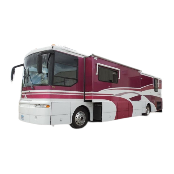
INTRODUCTION EXTERIOR FEATURE IDENTIFICATION Composite model shown for illustration purposes only. Actual locations of features depends on coach model and options. NOTE: Some equipment shown may be optional. *Also contains diesel fuel filter/water separator. **Also contains optional freezer unit if equipped. †Spoiler wing also contains rear monitor camera and clearance marker lights. -
Page 13: Section 1: Safety Precautions
SECTION 1 SAFETY PRECAUTIONS · Make sure all passengers have seat belts fas- Read and understand all instructions and pre- tened in a low and snug position so the force cautions in this manual before operating your exerted by the belt in a collision will be new motor home. -
Page 14: Fuel & Lp Gas
SECTION 1 SAFETY PRECAUTIONS · Driving through water deep enough to wet · Never use an open flame to test for LP gas the brakes may affect stopping distance or leaks. Replace all protective covers and caps cause the vehicle to pull to one side. Check on LP system after filling. -
Page 15: Lp Gas Leaks
SECTION 1 SAFETY PRECAUTIONS Press to stop alarm LP GAS LEAKS The following label is located in the vehicle near the range area. If you smell gas within the vehicle, quickly and carefully perform the proce- dures listed. IF YOU SMELL GAS 1. -
Page 16: Electrical
SECTION 1 SAFETY PRECAUTIONS work. The LP gas alarm breaker is located on the coach breaker fuse panel shown on page 6-8. Because the LP gas alarm is connected direct- ly to the auxiliary battery, it is always drawing a LOADING small amount of current. -
Page 17: Carbon Monoxide Warning
SECTION 1 SAFETY PRECAUTIONS · Each time the vehicle is raised for an oil FORMALDEHYDE INFORMATION change. · Whenever a change in the sound of the ex- WARNING haust system is noticed. Some components in this vehicle con- · Whenever the exhaust system, underbody or tain formaldehyde based adhesives rear of the vehicle is damaged. -
Page 18: Emergency Exit Window
SECTION 1 SAFETY PRECAUTIONS The CO alarm is powered by a 9-volt battery EMERGENCY EXITS and contains a sensor that is designed to detect Emergency Exit Windows toxic carbon monoxide gas fumes resulting from incomplete combustion of fuel. It will detect CO Your motor home is equipped with an emer- gas from any combustion source such as the fur- gency exit window on the left (driver’s) side of... -
Page 19: Fire Extinguisher
SECTION 1 SAFETY PRECAUTIONS should the need arise. To use the windows as exits, slide the window open, then slide the SMOKE ALARM screen open. Your motor home is equipped with a smoke alarm located on the ceiling in the galley and SAFETY DEVICES lounge area. - Page 20 SECTION 1 SAFETY PRECAUTIONS Install a new battery immediately. Be sure to use only batteries specified in manual or on unit. Test unit after installing a new battery. 3. Clean and vacuum the openings on your smoke alarm once a month.Do not open the smoke alarm or try to repair it.
-
Page 21: Before Entering Your Vehicle
SECTION 2 DRIVING YOUR MOTORHOME (See also Safety Precautions, Section 1 of this manual.) WARNING The engine should be shut off unless NOTE: See your Spartan chassis operator's man- specifically required for a certain pro- ual for information on starting the en- cedure. -
Page 22: Section 2: Driving Your Motor Home
125 gal. diesel The key number for your coach is registered in our factory database, so if you ever lose your keys, any Winnebago Industries dealership can STARTING AND easily order a new key for you. They are also... -
Page 23: Engine Block Heater
SECTION 2 DRIVING YOUR MOTOR HOME If a shoreline hookup is not available, just start the auxiliary generator to provide power to the engine heater. REMEMBER! Turn the engine heater switch off after starting the engine. The heater will keep operating for as long as it is supplied with elec- tricity. -
Page 24: Exhaust Braking System
SECTION 2 DRIVING YOUR MOTOR HOME HAZARD WARNING LIGHTS ® JACOBS EXTARDER™ ENGINE EXHAUST BRAKING SYSTEM The hazard warning flasher switch is located on the underside of the steering column near the To Use the Exhaust Brake: The exhaust brake signal/cruise lever. -
Page 25: Keyless Remote Entry System
SECTION 2 DRIVING YOUR MOTOR HOME Lubricate the locks periodically with graphite to maintain good working condition. CAUTION When releasing security night lock, be sure to retract bolt before opening door latch to prevent drag on bolt pin. Instruct all passengers in operation of this door catch system as well as emergency exit window. - Page 26 SECTION 2 DRIVING YOUR MOTOR HOME Recommended 12 volt battery: Gold Peak GP27A or GP23A Bronica B-1 Radio Shack #23-144 or #23-279 NOTE: Keys should always be removed when leaving the vehicle. Since doors can be locked without keys, make sure they have been removed from the ignition before locking the driver’s compartment.
-
Page 27: Entrance Step
SECTION 2 DRIVING YOUR MOTOR HOME Automatic Mode (Operates with Door) With the Power Switch on the On position the WARNING step is in Automatic Mode. This means it will ex- Do not use steps unless it is fully tend and retract automatically when the door is extended. -
Page 28: Power Electric Mirrors
SECTION 2 DRIVING YOUR MOTOR HOME you to stop the travel of the step cover while ex- tending, if necessary. It also allows you to manu- ally push the step cover back into the storage position for use of the step in case of low air pressure. -
Page 29: Remote Controlled Spot/Flood Light
SECTION 2 DRIVING YOUR MOTOR HOME Mirror Heat Switch Mirror Adjustment Control Select the mirror to be adjusted by pushing the Refer to the Owner’s InfoCase for specific switch in the middle of the control to the right or instructions provided by Sony. left. -
Page 30: Seats
SECTION 2 DRIVING YOUR MOTOR HOME Main SEATS Front Rear Seat Up/Down Up/Down Position The driver and co-pilot seats may be indepen- dently adjusted to suit individual preference. The seats may be swiveled to provide easy en- trance and exit. The swivel feature also allows the seats on some models to be turned toward the living area for additional seating while the unit is parked. -
Page 31: Seat Belts
SECTION 2 DRIVING YOUR MOTOR HOME To Fasten: Be sure belt is not twisted. Grasp each part of the belt assembly and push tongue into buckle. Adjust to a snug fit by pulling the loose end away from the tongue. To Release: Press button in center of buckle and slide tongue out of buckle. -
Page 32: Child Restraints
SECTION 2 DRIVING YOUR MOTOR HOME just shoulder belt height, press the lever • Inspect the belts and hardware periodically. down, select the desired position and re- Check for cuts, frays, and loose parts. Dam- lease the lever. A ratcheting mechanism aged parts should be replaced. - Page 33 SECTION 2 DRIVING YOUR MOTOR HOME attached to the restraint typically provides this information. 4. Review the instructions for installation and use of the restraint. Be sure that you under- stand them fully and can install the restraint properly and safely in your vehicle. 2-13...
-
Page 34: Instrument Panel
SECTION 2 DRIVING YOUR MOTOR HOME INSTRUMENT PANEL 12. Rearview (Backup) Monitor 1. Rearview Monitor Speaker 13. Cigarette Lighter/12V Socket 2. Windshield Wiper/Washer Switch 14. Radio/Cassette Player/CD Control 3. Aux. Start Switch 15. Automotive Heater/AC Controls 4. Fog Lamps Switch 16. -
Page 35: Multi-Function Signal Lever
SECTION 2 DRIVING YOUR MOTOR HOME MULTI-FUNCTION SIGNAL LEVER The multi-function signal lever controls the turn signals, high/low beam changing, and the electronic speed control (cruise). See your chassis operating guide for complete operating information. Pull to Tilt Push to Telescope To Adjust Telescoping Column: Push the lever toward the dash. -
Page 36: Comfort Controls
SECTION 2 DRIVING YOUR MOTOR HOME WINDSHIELD WASH/WIPE SWITCH 1. Front Heater Fan Switch 2. Temperature Control Knob Wash: Press the control knob to pump washer 3. Mode Selection Knob solution onto the windshield. The wiper will also begin operating. The wiper will continue for 5 wipes after you release the washer knob. -
Page 37: Air Conditioning
SECTION 2 DRIVING YOUR MOTOR HOME AIR CONDITIONING A. For maximum cooling. 1. Turn the mode selection knob to MAX A/C. 2. Turn the temperature control knob all the way left to the COOL (blue) position. 3. Turn the fan speed switch in to high (largest dot). -
Page 38: Compact Disc (Cd) Changer
SECTION 2 DRIVING YOUR MOTOR HOME • Place the Radio Power Switch in AUX posi- tion and the Ignition Switch in ACC posi- tion. • A speaker selector switch in the Video Cen- ter lets you switch the deluxe speakers to your desired sound source, whether the dash radio or the TV and VCR for theater sound listening. -
Page 39: Cb Radio Wiring
SECTION 2 DRIVING YOUR MOTOR HOME CB RADIO WIRING (Optional) Your coach is pre-wired for CB radio installa- tion. The wires are located beneath the dash to the left of the steering wheel. Look for a pair of wires, yellow (+) and white (-), with connectors and flag labels, suspended from the wiring harness. -
Page 40: Slideout Room Extension
SECTION 2 DRIVING YOUR MOTOR HOME CAUTION Do not try to drive vehicle unless ‘TRAVEL’ light is glowing with igni- tion switch on. Do not try to drive the vehicle until the air suspension system has built up sufficient pressure if you have used the coach leveling system or have used the DUMP button to manually exhaust the air suspension system. - Page 41 SECTION 2 DRIVING YOUR MOTOR HOME coach sidewall to maintain an effective weather seal while the vehicle is in motion. They are not designed to withstand the force exerted by the hydraulic extension mechanism and will not pre- vent extension of the room. Travel straps are located on the floor near the ends of the slideout room.
- Page 42 SECTION 2 DRIVING YOUR MOTOR HOME · Level the coach. · Set the Parking Brake. An interlock relay system will then provide power to the slide- out control switches. · Release travel straps. · Press slide-out switch and hold until room is fully extended, then release switch.
-
Page 43: Front Slideout Emergency Crank-In
SECTION 2 DRIVING YOUR MOTOR HOME · One of the fuses may be blown. Fuses are located on the interior firewall beneath the dash, beneath the instrument panel dash pod, and inside the leveling control pad housing. Unfasten the control pad from the driver side armrest panel to inspect the fuse. - Page 44 HEAT tighten. Overtightening may cause inter- REGISTER nal damage to the valves. See your Authorized Winnebago Industries Dealer for service of the slideout system before NOTE: Be sure the bracket extensions face away using again. from the slideout room as shown for proper support while cranking.
-
Page 45: Section 3: In Case Of Driving Emergency
When it is necessary to leave the vehicle, the Winnebago Industries does not assume re- flasher system will continue to operate with the sponsibility for damage incurred while towing ignition key removed. -
Page 46: Jump Starting
SECTION 3 IN CASE OF DRIVING EMERGENCY JUMP STARTING 2. Position the vehicle with the good battery so that the jumper cables will reach, but do not If your coach will not start from the automo- allow the vehicles to touch. tive batteries, try using the aux. -
Page 47: Connecting A Battery Charger
SECTION 3 IN CASE OF DRIVING EMERGENCY - a leak in the cooling system - a hose failure WARNING - water pump failure Do not attempt to push-start this vehi- cle. Damage to the transmission or Also, be aware of the following situations, other parts of the vehicle could occur. -
Page 49: Loading The Vehicle
SECTION 4 TRAVELING WITH YOUR MOTORHOME (See also SAFETY PRECAUTIONS, Section 1 of this manual.) FRONT AXLE TIRE LOADING THE ALIGNMENT VEHICLE We recommend that you have the front When loading the vehicle, distribute the cargo suspension and steering alignment checked and load equally so that you do not exceed either the adjusted after you have fully loaded the vehicle Front or Rear Gross Axle Weight Rating... -
Page 50: Section 4: Traveling With Your Motor Home
GVWR, the rear axle GAWR, or the ada. chassis GCWR. See preceding items “Loading To calculate the NCC or CCC, Winnebago the Vehicle” and “Weighing Your Loaded Vehi- uses vehicle sleeping capacity, however your cle” for explanation of these weight ratings. Al-... -
Page 51: Pre-Travel Checklist
SECTION 4 TRAVELING WITH YOUR MOTOR HOME WARNING WARNING For safety towing and vehicle hand- Never check oil level in generator ling, maintain proper trailer weight while engine is operating. distribution. - Fire Extinguisher - Make sure it is fully The total weight of the motor home charged and secured in mounting bracket. -
Page 52: Severe Weather Information
SECTION 4 TRAVELING WITH YOUR MOTOR HOME by wetting down, turning off the water, soap- the side view mirror frequently to observe ing thoroughly and then rinsing. how close you are driving to the center line. 4. Dump sewage only at approved dumping sta- tions. -
Page 53: Nighttime Driving
SECTION 4 TRAVELING WITH YOUR MOTOR HOME · During a flash flood, if you cannot move your recorded or “live” as the situation demands. vehicle, abandon it. Do not attempt to return The frequencies used for NOAA Weather Ra- to your vehicle before the water has receded. dio (National Oceanic and Atmospheric Admin- istration) nationwide are 162.40, 162.475 or ·... -
Page 54: Campsite Selection
SECTION 4 TRAVELING WITH YOUR MOTOR HOME DESCENDING A HILL may give false readings because water level is greater at one side of the tank than the other. When going down a long grade, you may need The refrigerator is installed level at the to manually shift to a lower gear, rather than factory. - Page 55 SECTION 4 TRAVELING WITH YOUR MOTOR HOME coach, you should take immediate action to min- imize their affects. You can help reduce exces- sive moisture inside the motor home by taking the following steps: Ventilate with outside air: Partially open one or more windows and a roof vent to circulate out- side air through the coach.
-
Page 57: Section 5: Lp Gas System
SECTION 5 LP GAS SYSTEM (See also Safety Precautions, Section 1 of this at each tank filling. Also inspect before and manual.) after each trip, and any time trouble is sus- pected. · Turn the LP supply valve off when not using the LP gas system. -
Page 58: Selecting Fuel Types
SECTION 5 LP GAS SYSTEM SELECTING LP FUEL TYPES LP TANK SYSTEM We recommend using straight propane in your The storage reservoir for the LP gas system is LP tank. Propane gas is commonly available at a horizontally mounted tank which is permanent- all LP gas outlets in the U.S. -
Page 59: Air In The Lp Gas Tank
SECTION 5 LP GAS SYSTEM NOTE: The LP tank is equipped with an auto- matic 80% stop-fill device. TRAVEL WITH LP GAS It is illegal for vehicles equipped with LP LP Gas Tank Capacity: tanks to travel on certain roadways or through certain tunnels in the U.S. -
Page 60: Regulator
SECTION 5 LP GAS SYSTEM REGULATOR The pressure regulator is protected from the elements by a plastic cover which should be left in place at all times. Only your dealer or a quali- fied LP gas service should remove the regulator cover for adjustments. -
Page 61: Winter Use Of Lp Gas
SECTION 5 LP GAS SYSTEM BTU’s Available at 0° F. IF YOU SMELL GAS Tank Level BTU’s 64,000 Extinguish any open flames, pilot lights and all 50,400 smoking materials. Do not touch electrical switches. 33,000 Shut off the gas supply at the tank valve(s) or gas supply connection. -
Page 63: Section 6: Electrical Systems
SECTION 6 ELECTRICAL SYSTEMS (See also Safety Precautions, Section 1 of this manual.) Your coach is equipped with an electrical sys- tem consisting of two separate voltages; a 12-volt DC system and a 110-volt AC system. The 12- volt system consists of two internal power sources, while the 110-volt system is operated from an outside power source, or from the optional 110-volt generator or 110-volt inverter... -
Page 64: Connecting The Shoreline
SECTION 6 ELECTRICAL SYSTEMS CONNECTING THE SHORELINE To connect to an external source, remove the cord from the storage compartment and plug the coach end of the cord into the coach input recep- tacle. (The coach end is the large, yellow plug.) 1. -
Page 65: Powerline Energy Management System
SECTION 6 ELECTRICAL SYSTEMS shoreline circuit breaker. This system works together with the energy efficient central air con- WARNING ditioner to allow you to run both compressor Do not plug the power cord into an units at the same time on a 30-amp shoreline outlet which is not grounded, or adapt connection. -
Page 66: Power Converter System
SECTION 6 ELECTRICAL SYSTEMS CAUTION Do not store items too closely around POWER CONVERTER the inverter unit in the storage com- SYSTEM partment. The inverter generates heat while operating and needs unre- The power converter changes 110-volt AC stricted airflow for proper cooling. current from the auxiliary generator or the shore- line into 12-volt DC current for use by 12-volt ·... - Page 67 SECTION 6 ELECTRICAL SYSTEMS 1 - Off 2 - Off 3 - Off 4 - Off 5 - Off 6 - Off 7 - Off 8 - On · 12-Volt House Circuit Breakers: The 12- Inverter Panel - Model 38KD volt house breaker panel contains pop-out On Model 40JD the Inverter Panel is located breakers;...
-
Page 68: 110-Volt Circuit Breakers
SECTION 6 ELECTRICAL SYSTEMS House 12V Breakers Model 40JD 110-Volt Circuit Breakers *Typical view of breaker panel. Actual fuse or breaker behind door on bedroom forward wall labels may vary according to appliance and equipment op- tions. Fuses and breakers are labeled on panel. CHARGING SECTION 110-VOLT CIRCUIT BREAKERS The house batteries are automatically charged... -
Page 69: Thermal Overload Protector
SECTION 6 ELECTRICAL SYSTEMS THERMAL OVERLOAD tion occurs, the GFCI will break the circuit by turning off the power to the protected outlets. If PROTECTOR this happens, unplug all the appliances on that A thermal overload protector will shut down circuit and press the reset button on the GFCI the converter if it becomes overheated. -
Page 70: Auxiliary 110-Volt Generator
SECTION 6 ELECTRICAL SYSTEMS · Systems Monitor Panel · Bedroom (underside of cabinet above bed) AUXILIARY 110-VOLT Starting The Diesel Generator GENERATOR 1. Press and hold the generator switch ON. 2. If the engine is cold, the starter will not Your coach is equipped with a diesel powered engage until after the glow plugs have pre- generator. - Page 71 SECTION 6 ELECTRICAL SYSTEMS 5. Allow the generator to stabilize running NOTE: While the generator is running it is nor- mal for the hourmeter to make a periodic before turning on appliances. “ticking” sound. 6. Apply electrical loads. Refer to SPECIFI- CATIONS section of generator manual for generator set output and performance OPERATION WARNINGS AND...
- Page 72 SECTION 6 ELECTRICAL SYSTEMS GENERATOR SLIDE OUT SERVICE 2. Push the power slide switch downward and TRAY: The generator service tray can be hold until generator frame is fully extended. extended and retracted by a power slideout Lift the switch upward and hold to retract the mechanism.
-
Page 73: 12-Volt Dc System
SECTION 6 ELECTRICAL SYSTEMS 12-VOLT CHASSIS CIRCUIT BREAKERS The 12-volt automotive and coach circuit breakers are located on a panel on the firewall in the engine compartment. See page 9-7 for fur- 12-VOLT DC SYSTEM ther information. The DC voltage system consists of the auto- motive batteries and the 12-volt coach auxiliary Auto Chassis 12-Volt Breaker Panel batteries. -
Page 74: Battery Information
SECTION 6 ELECTRICAL SYSTEMS BATTERY INFORMATION CHASSIS (Starting) BATTERY The chassis batteries are used solely to operate the engine starter and all automotive accessories and controls found on the instrument panel. This includes the horn, speed control, all exterior lights, radio, windshield wipers, rear auto heater fan, etc. -
Page 75: House Batteries
SECTION 6 ELECTRICAL SYSTEMS HOUSE BATTERIES A further precaution is to remove the battery from the vehicle and store it in a cool location on The house batteries supply current to all 12- a wooden or rubber pad, checking charge period- volt equipment located in the living area of the ically to avoid discharge or sulfating. -
Page 76: Trailer Wiring Connector
SECTION 6 ELECTRICAL SYSTEMS The diagram below shows proper connection WARNING of trailer or tow vehicle wiring to the coach light To prevent wiring damage, it is system. To access the wire connections inside the essential when replacing the cables plug, remove the small screw near the end of the on the battery, or when using a plug and slide the contact assembly out of the... -
Page 77: Section 7: Plumbing Systems
SECTION 7 PLUMBING SYSTEMS FRESH WATER SYSTEM Fresh Water Tank..99 gal. The fresh water system provides water to the galley sink, shower, bathroom lavatory, toilet and water heater. Water may be supplied by either of two sources: - a water tank located within the motor home, - any external water source to which the motor home may be connected, known as “city water”. -
Page 78: Water Pump
SECTION 7 PLUMBING SYSTEMS 5. Turn on pump switch. 6. Close each faucet as it begins to deliver a WATER PUMP steady stream of water (close cold water first). Leave hot water faucets on until they Pressure for the water system is supplied by a also deliver a steady stream of water. - Page 79 SECTION 7 PLUMBING SYSTEMS Adjusting Precharge Pressure the water system. If a 100 ppm concentration A tire-type valve stem is provided on the end is required as discussed in item 3, use 1/2 or top of the accumulator tank to check or add cup of household bleach with 1 gallon of air pressure.
-
Page 80: Water Purifier System
SECTION 7 PLUMBING SYSTEMS Water Filter Assembly - Below Galley Sink 4. Turn on the external water source. Replacing the water filter cartridge: Replace the filter cartridge when water flow from When connected to an outside source of the purifier faucet is too slow for convenience. water, the water bypasses the demand pump and storage tank and supplies pressure directly to ·... -
Page 81: Shower Hose Vacuum Breaker
SECTION 7 PLUMBING SYSTEMS See “Winterizing the Water Purifier System” Exterior Shower in Section 10. SHOWER HOSE VACUUM BREAKER After using the shower, you may notice water dripping from the shower faucet assembly. The dripping results when vacuum in the shower hose (after closing the shower faucet) slowly releases and allows water remaining in the hose to drain down. -
Page 82: Flushing Black Water Holding Tank
SECTION 7 PLUMBING SYSTEMS closed to avoid sewage back-up into grey 1. Dump your black water holding tank in the tank. Grey water also rinses any black usual manner at approved sewage disposal water solids from the drain hose. station. 2. -
Page 83: Utility Light
SECTION 7 PLUMBING SYSTEMS When using a sewer hook-up, keep the dump when preparing the motor home for storage or valves closed until a tank becomes full or when when sanitizing the water system. preparing to leave the site. This keeps the solids in suspension, allowing them to be carried out To Drain Tanks and Water Lines: with the liquids when the dump valve is opened. -
Page 84: Tank Capacities
SECTION 7 PLUMBING SYSTEMS Water Heater Drain Plug: The water heater drain plug is located on the outside of the coach behind the water heater service panel. Use a socket to remove the plug. Drain Plug Water Tank Drain Valve (pull to open) Shower Line Drain Valve: Water Heater... - Page 85 SECTION 8 APPLIANCES & INTERIOR FEATURES (See also Safety Precautions, Section 1 of this manual.) CAUTION To prevent permanent damage to the NOTE: Some items described in this section may refrigerator cooling unit, turn the be optional and, therefore, may not be in refrigerator off if the vehicle will be your vehicle.
- Page 86 SECTION 8 APPLIANCES & INTERIOR FEATURES The ON/OFF button (E) turns the refrigera- available, an alarm will sound and the refrigera- tor on or off. If the button is pressed, it will turn tor will cease operation. Refer to the Diagnostic the refrigerator on and set the mode to auto.
- Page 87 SECTION 8 APPLIANCES & INTERIOR FEATURES will display Diagnostic Code C5 and will switch ICE MAKER - Norcold automatically to the BOS mode. This mode pro- Some Norcold refrigerators are optionally vides refrigeration until the refrigerator is ser- equipped with an automatic ice maker system. viced.
- Page 88 SECTION 8 APPLIANCES & INTERIOR FEATURES SHUT-OFF ARM ICE BIN 4. Start the refrigerator the day before ice cubes Ice Maker Water Supply Connection are needed. When the refrigerator is started 3. Let the ice maker run through a cycle, then (from room temperature), it is normal to take raise the shut-off arm.
-
Page 89: Lp Gas Cooktop
SECTION 8 APPLIANCES & INTERIOR FEATURES B. If too much, attach water pressure regula- B. Check door gasket for proper sealing. tor. 4. Is the water supply inlet valve on? A. If not enough, turn city water faucet open REFRIGERATOR SERVICE ACCESS further or check for blockage. -
Page 90: Microwave Convection Oven
SECTION 8 APPLIANCES & INTERIOR FEATURES Lighting Cooktop Burners (w/Pilotless Ignition) 1. Be sure LP gas tank main supply valve is open. 2. Rotate the Spark knob clockwise to provide ignition spark. 3. While rotating the Spark knob, turn the selected Burner knob to ON. -
Page 91: Monitor Panel
SECTION 8 APPLIANCES & INTERIOR FEATURES switches are located on the microwave control panel. To Clean Grease Filter or Replace Light Bulb See the manufacturer’s information in your Owner InfoCase for instructions on replacement of light bulbs and grease filter elements. SYSTEMS MONITOR PANEL The monitor panel provides central location of switches for the water pump battery meter and... -
Page 92: Water Pump Switch
SECTION 8 APPLIANCES & INTERIOR FEATURES at that level. There is generally more water in a tank than indicated on the monitor panel. For example, a water level of 1-2” below the FULL probe, the monitor will show the level to be only 2/3 even though the tank is nearly full. -
Page 93: Washer-Dryer
SECTION 8 APPLIANCES & INTERIOR FEATURES Water Supply Faucets GAS/ELECTRIC WATER HEATER WASHER-DRYER (Optional) For complete operating instructions, see the Water Heater Capacity: 10 gal. manufacturer’s information provided in your Owners InfoCase. The 10 gallon water heater has a dual power feature. - Page 94 Do not use a phone in your coach. Follow the dealer’s or gas sup- plier’s instructions. • If you cannot reach a Winnebago Industries dealer or a local gas supplier, call the fire department. • Have the source of the leak corrected before using the LP gas system again.
- Page 95 SECTION 8 APPLIANCES & INTERIOR FEATURES 7. If lockout happens before main burner lights, P-T Valve turn switch OFF, wait five seconds and turn (Lift Straight Out Slowly - switch back on. This will restart the ignition Let Snap Back) cycle.
-
Page 96: Lp Gas Furnace
SECTION 8 APPLIANCES & INTERIOR FEATURES 4. Let the handle of the P-T valve snap shut. To Shut Down: 1. Slide thermostat/system switch OFF. 5. Close the faucet and turn on the water supply 2. Close LP tank valve. before switching the water heater on. Manually operate the pressure temperature re- For Further Information lief valve at least once a year. -
Page 97: Heat Pump
SECTION 8 APPLIANCES & INTERIOR FEATURES • Adjust the temperature setpoint to personal preference if needed. See “Changing Tem- perature Setpoints”. Fan: • Slide the system switch down to “Fan” posi- tion. The fan will run continuously at high speed and is not controlled by thermostat set- ting. -
Page 98: Central Air Conditioner
SECTION 8 APPLIANCES & INTERIOR FEATURES • To turn the heat pump Off and use the LP gas air returns to the air conditioner through a filter Furnace only, place the switch in GAS posi- system beneath the rear bed. (See “Air Condi- tion. -
Page 99: Tv Antenna
SECTION 8 APPLIANCES & INTERIOR FEATURES A/C Filter Size: 14” x 20” x 1” Operation Raising Antenna - Turn elevating crank NOTE: Do not block the filter in any way, such clockwise in “UP” direction about 13 turns or as by setting packages or newspapers, until some resistance to turning is noted. -
Page 100: Digital Satellite System
SECTION 8 APPLIANCES & INTERIOR FEATURES Turn elevating crank (counterclockwise) in To check the antenna amplifier, raise the an- “DOWN” direction until resistance is noted. tenna, select a TV channel and rotate the antenna Antenna is now locked in travel position. Turn for best picture. -
Page 101: Video Selector System
SECTION 8 APPLIANCES & INTERIOR FEATURES signal from, such as cable TV, VCR, the roof VIDEO SELECTOR SYSTEM antenna, or satellite dish antenna. Press the cor- responding button to connect to the desired sig- nal source. The video selector system allows you to switch the antenna, cable TV, satellite TV system •... -
Page 102: Central Vacuum Cleaner
SECTION 8 APPLIANCES & INTERIOR FEATURES CABLE TV AND PHONE HOOK-UPS (Input) The cable television and telephone input con- nectors are located in the shoreline compartment. The cable and phone lines can be routed through the hatch in the bottom of the compart- ment so the door can remain shut while connect- Front Phone Jack: On rear facing end of the passenger sidewall armrest just behind the copi-... -
Page 103: Bedroom Radio
SECTION 8 APPLIANCES & INTERIOR FEATURES Hose Connector Access Panel Central Vacuum Cleaner System See the Audiovox operator guide on your Owner InfoCase for full operating instructions by To Change Filter Bags: Remove the lower the manufacturer. drawer from the refrigerator cabinet and pull the cover from the square metal canister. -
Page 104: Dinette Chairs
SECTION 8 APPLIANCES & INTERIOR FEATURES Pull the leaf upward out of the pocket using NOTE: Fastening and unfastening will be the handle provided. easier if you clip the open end of the snap hook upward onto the wall loop bracket as shown. Lower the leaf into position and slide the table top toward the wall. -
Page 105: Sleeping Facilities
SECTION 8 APPLIANCES & INTERIOR FEATURES SLEEPING FACILITIES WARNING Do not use sleeping facilities while vehicle is moving. COUCH-BED CONVERSION To Convert Sofa to Bed: • Pull the front edge of the sofa seat upward and outward from the wall while pushing downward on the backrest until the cushions lie flat. -
Page 106: Power Roof Vents
SECTION 8 APPLIANCES & INTERIOR FEATURES 2. To flush the toilet, push the lever all the way See instructions in Section 10 to prepare the down until sewage leaves the toilet and bowl toilet for storage in freezing conditions. is rinsed clean. 3. -
Page 107: Slider Windows
SECTION 8 APPLIANCES & INTERIOR FEATURES Fan On/Off Fuse Fan Speed Switch Selector Auto/Manual Manual Dome Elevation Dome Crank Switch Power Ventilator SLIDER WINDOWS Swing the latch handle straight out from the window. Grasp the sliding window edge frame and slide the window to the side. Be sure the latch is open before trying to slide the window closed. -
Page 109: Roof
Appropri- not recommended, however, that very large or ate compounds are sold at Winnebago and Itasca heavy objects be carried on the roof while the ve- dealers, and the materials are quickly and easily hicle is in motion. -
Page 110: Compartment Doors
SECTION 9 CARE & MAINTENANCE - Test any cleaning solution on a small section shades should be closed when the motor of decal before using. home is parked for an extended period of - Do Not use any aromatic solvents such as time. -
Page 111: Tables And Countertops
SECTION 9 CARE & MAINTENANCE Care Instructions NOTE: Cabinetry and furniture items through- out this motor home are constructed ei- t Spot clean with mild soap and water. ther partially or completely of real t Air dry, or dry quickly with hair dryer on warm hardwoods. -
Page 112: Vinyl Wallboard
SECTION 9 CARE & MAINTENANCE VINYL WALLBOARD face material and should be cleaned with a mild soap and water solution. Abrasive cleaners or Decorative vinyl covered wallboards may be harsh detergents should not be used. See “Tables cleaned with a mild soap and water solution. Do and Countertop Surfaces”... - Page 113 SECTION 9 CARE & MAINTENANCE Air Filter Engine Oil Indicator Dipstick Top View of Engine with Cover Open (beneath rear bed) Transmission Fluid Oil Fill Engine Coolant Dipstick/Fill Tube Tube Reservoir FUEL/WATER SEPARATOR Diesel fuel often contains small quantities of With the service panel open, you can access water which can damage the engine if not filtered the following service points:...
-
Page 114: Engine Cooling System
SECTION 9 CARE & MAINTENANCE See the Vehicle Certification Label affixed to the wall near the driver’s seat for tire informa- tion. WARNING Make sure all replacement tires are of the same size and ply rating as those installed as original equipment. Fuel/Water Drain Valve SUSPENSION ALIGNMENT Dispose of the drained liquid in an environ-... -
Page 115: Windshield Washers And Wipers
SECTION 9 CARE & MAINTENANCE switch. An overload on the breaker will cause the WINDSHIELD WASHERS AND lights to flicker on and off. Headlight wiring WIPERS should be checked immediately anytime this con- dition is apparent. Refer to your chassis operating See your chassis operating guide for recom- guide for further information. -
Page 117: Section 10: Storing Your Motor Home
SECTION 10 STORING YOUR MOTOR HOME 2. Level the motor home and drain the entire PREPARING VEHICLE FOR plumbing system as described in the follow- STORAGE ing steps. 3. Then turn on Wash Station Shower Head and Properly preparing your vehicle for storage lay shower head on ground to drain any will lessen the possibility of damage to your water left in shower line. - Page 118 SECTION 10 STORING YOUR MOTOR HOME NOTE: If your coach is equipped with the refrig- NOTE: Before using again the following erator ice maker option, the ice maker spring: water lines must also be drained. See “Winterizing the Ice Maker” on page •...
- Page 119 30 psi or less to force air sink drain and shower drain. This prevents through the system. (A “blow-out” plug can any holding tank odors from entering the be purchased at any Winnebago or Itasca coach during storage. dealer. P/N 701705-01-000.) WARNING...
- Page 120 SECTION 10 STORING YOUR MOTOR HOME tainer to determine the correct 24. Wash and wax the coach. amount to use for your coach. 25. Inspect all seams and seals around doors, windows, vents, and any other joints. See “RV ANTIFREEZE WATER Replace or repair any that are damaged.
-
Page 121: Removal From Storage
SECTION 10 STORING YOUR MOTOR HOME 2. Have the entire LP gas system checked for leaks. 3. Check window operation. 4. Check cabinet and door hinges. Lubricate with penetrating oil, if necessary. 5. Close all faucets and drain valves that are open. - Page 123 INDEX LP Gas Tank..........5-2 Accumulator Tank, Water System....7-2 Water Heater ..........8-9 Air Conditioner, Automotive ....... 2-16 Carbon Monoxide Alarm ......1-5 Air Conditioner, Central ......8-14 Carbon Monoxide Warning ......1-5 Air Conditioner Filter ........8-14 Carpets, Care of ..........9-2 Air Release, Stepwell Cover ......
- Page 124 INDEX Dishwasher Info ..........8-8 Filling ............7-1 Disinfection of Fresh Water Tank ....7-3 Fresh Water Toilet ........8-21 Door Handles and Locks........ 2-4 Front Axle Tire Alignment ......4-1 Doors and Windows, Care of......9-4 Fuel Selection ..........2-2 Drain Valves, Water ........
- Page 125 INDEX LP Gas Pressure Regulator ......5-4 Recovery Towing........... 3-1 LP Gas Safety ..........5-1 Refrigerator ........... 8-1 LP Gas Selection..........5-2 Regulator, LP Gas ........5-4 LP Gas Tank, Air in the ....... 5-3 Relief Valve, Water Heater......8-11 LP Gas Tank, Refilling ........
- Page 126 INDEX Water Heater ..........8-9 Table and Countertop Surfaces...... 9-3 Water Heater Capacity........8-9 Table, Dinette..........8-19 Water Line Drain Valves ....... 7-7 Tank , Fresh Water Filling ......7-1 Water Pump ........... 7-2 Tank Capacities, Water and Holding ..... 7-8 Water Pump Switch .......
- Page 127 IMPORTANT SERIAL NUMBERS Motor Home (Coach): Year _________ Model ___________________ Serial _____________ Chassis: Make ___________________ Serial (VIN) ______________ Roof Air Conditioner: Brand ___________ Model ____________ Serial _ ___________ Furnace: Brand ___________ Model ____________ Serial _ ___________ Water Heater: Brand ___________ Model ____________ Serial _ ___________ Power Converter: Brand ___________ Model ____________ Serial _ ___________ 110-Volt Generator:...
- Page 128 MAINTENANCE RECORD Odometer Date Mileage Description of Service Cost...
- Page 129 FUEL & OIL RECORD Odometer Fuel Odometer Fuel Date Mileage Gal. Qts. Cost Date Mileage Gals. Qts. Cost...
- Page 130 FUEL & OIL RECORD Odometer Fuel Odometer Fuel Date Mileage Gal. Qts. Cost Date Mileage Gals. Qts. Cost...
Need help?
Do you have a question about the 2000 Freedom and is the answer not in the manual?
Questions and answers