Table of Contents
Advertisement
Quick Links
Advertisement
Table of Contents

Related Manuals for Ubiquiti mPort-S mPort Serial


Summary of Contents for Ubiquiti mPort-S mPort Serial
- Page 1 mFi Networked Serial Interface Model: mPort-S...
-
Page 3: Package Contents
Introduction Introduction Thank you for purchasing the Ubiquiti Networks mFi ™ mPort Serial. The mPort Serial is designed for use with ™ the mFi platform. Once connected, you can use the mFi Controller software to monitor your devices and define automation rules using your web browser. -
Page 4: Hardware Overview
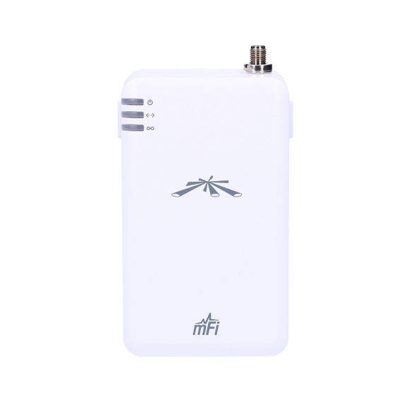
mPort Serial ™ ™ Hardware Overview Front View Antenna Connector Power LED Ethernet LED Status LED Power The Power LED will light steady green when the mPort Serial is properly connected to a power source. Ethernet The Ethernet LED will light steady green when an active Ethernet connection is made and flash when there is activity. -
Page 5: Side View
Hardware Overview Side View Ethernet Port Wall-Mount Bracket Serial DB9 Port Serial TB Port Port Serial DB9 Port Connects to a switch, router, or other device for remote access. Serial TB (Terminal Block) Port Connects to an industrial networking device for automation, such as script execution from the mFi Controller software. -
Page 6: Hardware Installation
mPort Serial ™ ™ Hardware Installation Remove the Wall-Mount Bracket from the mPort Serial by pressing the Release Tabs. Release Tabs Wall-Mount (Optional) Position the Wall-Mount Bracket with the Release Tabs on top. Release Tab Release Tab... - Page 7 Hardware Installation To secure the Wall-Mount Bracket to the wall: a. Use a pencil to mark the holes on the wall. b. Use a 6 mm drill bit to drill the holes in the wall. c. Insert the four Anchors into the wall. d.
- Page 8 mPort Serial ™ ™ Antenna Installation (Optional) The mPort Serial uses the internal antenna by default. If you want to use an external antenna, then attach the included Antenna and configure its use in the mFi Controller software.
-
Page 9: Connecting A Serial Device
Connecting a Serial Device Connecting a Serial Device Each serial port supports RS232, RS422, and RS485. Use the appropriate serial port for your serial cable (not included). Note: Only one serial port can be used at a time. Serial DB9 Connect one end of the serial cable to the console port of the switch, router, or other device. - Page 10 mPort Serial ™ ™ Serial TB The Serial TB port is labeled for RS485 pinout. The table lists the pinouts for RS232, RS422, and RS485. For more information, refer to the mFi User Guide available at www.ubnt.com/mfi Function Ground Pinout ✓...
- Page 11 Connecting a Serial Device Wire the other end of the serial cable to the Terminal Block included with the mPort Serial. Insert the Terminal Block into the Serial TB port of the mPort Serial.
- Page 12 mPort Serial ™ ™ Connecting Ethernet and Power Connect an Ethernet cable to the Ethernet port on the mPort Serial. Connect the other end of the Ethernet cable to the Ethernet port labeled POE on the PoE Adapter.
- Page 13 Connecting Ethernet and Power Connect an Ethernet cable from your LAN to the Ethernet port labeled LAN on the PoE Adapter. Note: Wi-Fi settings for the mPort Serial can be configured via LAN or by connecting an Ethernet cable directly from your computer to the LAN port on the PoE Adapter.
-
Page 14: Software Download And Installation
Controller software locally. Skip to Accessing the Configuration Portal on page 19. The mFi Controller software can be downloaded from the Ubiquiti Networks website. Go to downloads.ubnt.com/mfi Mac users should download mFi.dmg and Windows users should download mFi-installer.exe. - Page 15 Software Download and Installation Click Continue and follow the on-screen instructions to install the software. Go to Go > Applications and double-click the mFi icon. Proceed to Configuring the mFi Controller Software on page 16.
- Page 16 mPort Serial ™ ™ PC Users Launch mFi-installer.exe. Click Install. If your computer doesn’t have Java 1.6 or above installed, you will be prompted to install it. Click Install to continue.
- Page 17 Software Download and Installation Ensure that the Start mFi Controller after installation option is checked and click Finish. Note: The mFi Controller software can also be launched from Start > All Programs.
- Page 18 mPort Serial ™ ™ Configuring the mFi Controller Software The mFi Controller software startup will begin. Click Launch a Browser to Manage the Network. The mFi Configuration Wizard will appear the first time you launch the mFi Controller software. On the Welcome screen, select your language and country.
- Page 19 Software Download and Installation Select the device(s) that you want to configure. The Refresh button can be used to refresh the list of devices. Click Next to continue. Enter an administrator name in the Admin Name field. Enter a password in the Password and Confirm fields. Click Next.
- Page 20 mPort Serial ™ ™ Click Finish to confirm your settings. A login screen will appear for the mFi Controller management interface. Enter the Admin Name and Password that you created and click Login.
- Page 21 Accessing the Configuration Portal Accessing the Configuration Portal You need to connect to the Configuration Portal to configure any of the following: • Cloud access • Access to local mFi Controller on a different IP network • Wireless network access (Wi-Fi settings) Note: If you are not using these configurations, you do not need to access the Configuration Portal.
- Page 22 Serial ™ ™ Configuration Portal via LAN with DHCP If it is not already installed, download the Ubiquiti Device Discovery Tool (v2.3) at www.ubnt.com/download#app Launch the Ubiquiti Device Discovery Tool. A list of Ubiquiti devices on the network will appear.
- Page 23 Accessing the Configuration Portal Configuration Portal Interface Settings The login screen will appear. Enter ubnt in the Username and Password fields. Note: Once a device has been connected to the cloud, the Configuration Portal login information changes. The new username/password combination can be found on the Info tab in the cloud UI.
- Page 24 mPort Serial ™ ™ Enter your configuration information on the Configuration tab: mFi Controller Enter the mFi Controller settings: a. Enter the mFi Controller address. • For local mFi Controller installations, this is the IP address and http port used by the Controller. (The port is usually 6080, for example: 192.168.25.161:6080 or mfi.acme.com:6080) •...
- Page 25 Accessing the Configuration Portal Wireless Settings To use the mPort Serial on a Wi-Fi network, configure the Wireless Settings: a. Click Scan for a list of available SSIDs. Select the appropriate SSID or type in the name manually in the SSID field. b.
-
Page 26: Specifications
mPort Serial ™ ™ Specifications mPort Serial Dimensions 100 x 60 x 27.5 mm (H x W x D) 100 x 60 x 36.5 mm (with Bracket) Weight 119 g (with Bracket) Power Supply 24V, 0.5A Surge Protection Integrated PoE Adapter (Included) Max. -
Page 27: General Warranty
Products furnished hereunder shall be free from defects in material and workmanship for a period of one (1) year from the date of shipment by UBIQUITI NETWORKS under normal use and operation. UBIQUITI NETWORKS sole and exclusive obligation under the foregoing warranty shall be to repair or replace, at its option, any defective Product that fails during the warranty period. -
Page 28: Warranty Conditions
Disclaimer: UBIQUITI NETWORKS does not warrant that the operation of the products is error-free or that operation will be uninterrupted. In no event shall UBIQUITI NETWORKS be responsible for damages or claims of any nature or description relating to system performance, including coverage, buyer’s selection of products for buyer’s... -
Page 29: Safety Notices
Safety Notices Safety Notices 1. Read, follow, and keep these instructions. 2. Heed all warnings. 3. Only use attachments/accessories specified by the manufacturer. WARNING: Do not use this product in location that can be submerged by water. WARNING: Avoid using this product during an electrical storm. -
Page 30: Rf Exposure Warning
Serial ™ ™ Compliance Changes or modifications not expressly approved by Ubiquiti Networks, Inc. could void the user’s authority to operate the equipment. This device complies with Part 15 of the FCC Rules. Operation is subject to the following two conditions: 1. -
Page 31: Industry Canada
Compliance Industry Canada Under Industry Canada regulations, this radio transmitter may only operate using an antenna of a type and maximum (or lesser) gain approved for the transmitter by Industry Canada. To reduce potential radio interference to other users, the antenna type and its gain should be so chosen that the equivalent isotropically radiated power (e.i.r.p.) is not more than that necessary for successful communication. -
Page 32: Declaration Of Conformity
UBIQUITI NETWORKS device, megfelel a vonatkozó alapvetõ követelményeknek és az 1999/5/EC irányelv egyéb elõírásainak. Íslenska [Icelandic] Hér me l sir UBIQUITI NETWORKS yfir ví a UBIQUITI NETWORKS device, er í samræmi vi grunnkröfur og a rar kröfur, sem ger... - Page 33 UBIQUITI NETWORKS device, è conforme ai requisiti essenziali ed alle altre disposizioni pertinenti stabilite dalla direttiva 1999/5/CE. Latviski [Latvian] Ar o UBIQUITI NETWORKS deklar , ka UBIQUITI NETWORKS device, atbilst Direkt vas 1999/5/EK b tiskaj m pras b m un citiem ar to saist tajiem noteikumiem.
- Page 34 Serial ™ ™ mFi Products Ubiquiti Networks offers a variety of products for the mFi platform. For additional details, visit www.ubnt.com/mfi Ceiling Mount Wall Mount Temperature Motion Sensor Motion Sensor Sensor mFI-MSC mFi-MSW mFi-THS Current Sensor Door Sensor Thermostat...
- Page 36 Support support.ubnt.com Wiki Page wiki.ubnt.com Support Forum forum.ubnt.com Downloads downloads.ubnt.com w w w . u b n t . c o m © 2012-2013 Ubiquiti Networks, Inc. All rights reserved.
Need help?
Do you have a question about the mPort-S mPort Serial and is the answer not in the manual?
Questions and answers