Table of Contents
Advertisement
Quick Links
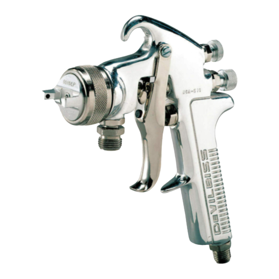
SERVICE MANUAL
JGA-510 (HVLP)
SUCTION/PRESSURE FEED
SPRAY GUN
MAJOR REPAIR KIT KK-4987-2
(GOVERNMENT NSN NO. 4940-01-046-9919 = KK-4987-2)
MINOR REPAIR KIT KK-5034
IMPORTANT: Before using this equipment,
read all safety precautions and instructions.
Keep for future use.
DESCRIPTION
The high volume low pressure JGA-HVLP gun
is designed to apply a wide variety of finish-
ing materials. This gun was manufactured
to provide maximum transfer efficiency by
limiting air cap pressure to 10 psi (complies
with rules issued by SCAQMD and other air
quality authorities). The gun is available in
both suction feed and pressure feed versions
of fluid delivery.
This gun will produce approximately
10 psi cap pressure at 50 psi gun inlet
pressure, as measured at the gun inlet.
An air cap test kit (see Accessories, Page
6) should be used to insure 10 psi air cap
pressure is not exceeded.
Note
This gun includes 300 series
stainless steel fluid passages
and 400 series tip and needle.
Guns may be used with chlorinated
solvent materials. See Page 2 for
additional warnings.
IMPORTANT: This gun may be used with
most common coating and finishing ma-
terials. It is designed for use with mildly
corrosive and nonabrasive materials. If
used with other high corrosive or abra-
sive materials, it must be expected that
frequent and thorough cleaning will be
required and the necessity for replacement
of parts will be increased.
INSTALLATION
For maximum transfer efficiency, do not use
more pressure than is necessary to atomize
the material being applied.
Connect the gun to a clean, moisture and oil
free air supply using a hose size of at least
5/16" I.D. Do not use 1/4" I.D. hose (25' x 1/4"
hose at 18 CFM has a pressure loss of 25 psi.
25' x 5/16" hose at 18 CFM has a pressure
loss of 8 psi.
Note
Depending on hose length, larger
I.D. hose may be required. Install a
HAV-501 air gauge at the gun handle
and air cap test kit over tip. When
gun is triggered on, adjust regulated
pressure to desired setting to pro-
vide a maximum of 10 psi at the air
cap. Do not use more pressure than
SB-2-248-M (9/2015)
is necessary to atomize the mate-
rial being applied. Excess pressure
will create additional overspray and
reduce transfer efficiency.
Note
If quick connects are required,
use only high flow quick con-
nects approved for HVLP use
such as DeVilbiss HC-4419 &
HC-4699. Other types will not flow
enough air for proper gun operation.
Note
If an air adjusting valve is used
at the gun inlet, use DeVilbiss Model
HAV-500 or HAV-501. Some compet-
itive adjusting valves have signifi-
cant pressure drop that can adverse-
ly affect spray performance. Models
HAV-500 and 501 have minimal
pressure drop, which is important
for HVLP spraying.
OPERATION
Strain material thru 60 or 90 mesh screen.
Best atomization will occur with 10 psig
air cap pressure. However, some materials
can be sprayed at lower pressures, improving
transfer efficiency.
Open fluid adjusting screw (27) by turning
counterclockwise. If gun is a suction feed
version, make sure vent hole in suction
cup is clean. If gun is a pressure feed
version, turn on air to paint supply
and adjust fluid pressure to deliver the
desired paint volume.
Turn on air supply to gun and set gun
inlet pressure to lowest recommended
pressure for material being sprayed. Spray
a test area. Air pressure and paint flow
should be adjusted to provide a uniform
dispersion of atomized paint throughout
the pattern. Keep air pressure as low as
possible to minimize bounce-back and
overspray. Excessive fluid flow will result
in heavy center spray patterns. Inade-
quate flows may cause the pattern to split. See
TROUBLESHOOTING, page 5, if any problems
occur. If finer atomization is required, increase
gun inlet pressure. If a reduced fluid flow rate
is required, turn fluid adjusting screw (27)
clockwise until desired fluid flow is obtained
or reduce fluid pressure (pressure feed only).
Order a free copy of Spray Gun Troubleshoot-
ing and Preventive Maintenance Guide, SB-
2-001 latest revision, for details concerning
setup of spray guns.
1 / 8
PREVENTIVE MAINTENANCE
To clean air cap and fluid tip, brush exterior
with a stiff bristle brush. If necessary
to clean cap holes, use a broom straw
or toothpick. Never use a wire or hard
instrument. This may scratch or burr
holes causing a distorted spray pattern. See
page 6 for gun cleaning accessories.
To clean fluid passages, remove excess
material at source Then proceed as follows:
Suction Feed Guns - Wash out cup with
solvent. Wipe off cup suction tube, then
fill cup with solvent. Spray until fluid
passages are clean.
Pressure Feed Guns - Flush fluid delivery sys-
tem with a suitable solvent using a device such
as the SolventSaver™ (see ACCESSORIES).
Wipe exterior with a solvent dampened cloth,
or use 29-3100 Scrubs
(shown on page 6.)
®
Never completely immerse in solvent as this
is detrimental to the performance and gun
life expectancy, as well as destroying the
lubricants and packings.
Note
When replacing the fluid tip or fluid
needle, replace both at the same
time. Using worn parts can cause
fluid leakage. See Chart 1 for order-
ing information. Also, replace the
needle packing at this time. Lightly
lubricate the threads of the fluid tip
before reassembling.
Torque to
20-25 ft. lbs.
To prevent damage to fluid tip
(3) or fluid needle (32), be sure
to either 1) pull the trigger and
hold while tightening or loos-
ening the fluid tip, or 2) re-
move fluid needle adjusting screw
(27) to relieve spring pressure
against needle collar.
EN
Advertisement
Table of Contents

Related Manuals for DeVilbiss JGA-510


Summary of Contents for DeVilbiss JGA-510
-
Page 1: Spray Gun
If an air adjusting valve is used solvent. Wipe off cup suction tube, then of fluid delivery. at the gun inlet, use DeVilbiss Model fill cup with solvent. Spray until fluid HAV-500 or HAV-501. Some compet- passages are clean. -
Page 2: Safety Precautions
SAFETY PRECAUTIONS This manual contains information that is important for you to know and understand. This information relates to USER SAFETY and PREVENTING EQUIPMENT PROBLEMS. To help you recognize this information, we use the following symbols. Please pay particular attention to these sections. Note Important information that tells how to Information that you should pay special... -
Page 3: Spray Gun Lubrication
•A Material Safety Data Sheet is available baffle gasket and gun body. See Part No. Baffle Air Cap Baffle from DeVilbiss upon request. Figure 2. Do not loosen the fluid tip JGHV-101-57 JGHV-457-57 more than three (3) turns, as Trigger Points damage may occur. -
Page 4: Parts List
#Ref. No. 34 includes Ref. Nos. 3 and 32. Copper tip gasket also 34411-122-K10 Packing Nut Kit (Kit of 10) ....... 1 included but not used with JGA-510 gun. — Screw ............1 Sufixes -K10 designates kit of multiple parts. Example: JGS-478 Stud and Screw Kit ........ - Page 5 TROUBLESHOOTING CONDITION CAUSE CORRECTION Heavy top or Clean. Ream with non-metallic point. Horn holes plugged. bottom pattern Clean. Obstruction on top or bottom of fluid tip. Clean. Cap and/or tip seat dirty. Heavy right or left Clean. Ream with non-metallic point. Left or right side horn holes plugged.
- Page 6 Joins any single piece C o m p a t i b l e w i t h DeVilbiss air cap with a l l p a i n t m a t e r i a l s : latest version MBC-368...
- Page 7 NOTES SB-2-248-M (9/2015) 7 / 8...
-
Page 8: Warranty Policy
WARRANTY POLICY DeVilbiss products are covered by Finishing Brands one year materials and workmanship limited warranty. The use of any parts or accessories, from a source other than Finishing Brands, will void all warranties. For specific warranty information please contact the closest Finishing Brands location listed below.
Need help?
Do you have a question about the JGA-510 and is the answer not in the manual?
Questions and answers