COBHAM SAILOR 6210 VHF User And Installation Manual
Hide thumbs
Also See for SAILOR 6210 VHF:
- Installation manual (468 pages) ,
- User and installation manual (78 pages)
Table of Contents
Advertisement
Quick Links
Advertisement
Table of Contents

Related Manuals for COBHAM SAILOR 6210 VHF


Summary of Contents for COBHAM SAILOR 6210 VHF
- Page 1 SAILOR 6210 VHF User and installation manual...
- Page 3 SAILOR 6210 VHF User and installation manual Document number: 98-128432-THR-F Release date: October 15, 2013...
- Page 4 Thrane & Thrane A/S is not responsible for the content or accuracy of any translations or reproductions, in whole or in part, of this manual from any other source. Thrane & Thrane A/S is trading as Cobham SATCOM. Copyright © 2013 Thrane & Thran3 A/S. All rights reserved. Printed in Denmark.
-
Page 5: Safety Warning
Safety warning The following general safety precautions must be observed during all phases of operation, service and repair of this equipment. Failure to comply with these precautions or with specific warnings elsewhere in this manual violates safety standards of design, manufacture and intended use of the equipment. -
Page 6: Emergency Calls
Emergency calls M M M M M ak ak ak ak ake sur e sur e sure e e e e your e sur your your V V V V V HF your HF HF HF R R R R Radi adio o o o o i i i i i s on C s on C s on C... -
Page 7: Manual Overview
SAILOR 6210 VHF is designed for occupational use only and must be operated by licensed personnel only. SAILOR 6210 VHF is not intended for use in an uncontrolled environment by general public. SAILOR 6210 VHF is designed for installation by a skilled service person. -
Page 9: Table Of Contents
Hailer and Fog horn setup ............. 25 Replay function .................. 26 Chapter 3 Installation Unpacking the SAILOR 6210 VHF ..........27 Installing the VHF radio ..............28 Power, VHF antenna and external equipment ..... 35 System setup ..................42 SAILOR 6201 Handset cradle (optional) ........ 43 Chapter 4 Service &... - Page 10 Table of Contents Equipment and accessories ............48 Warranty ....................48 App. A Technical specifications App. B Maritime channels App. C Declaration of conformity Glossary ........................57 Index ........................59 viii...
-
Page 11: Chapter 1 Introduction
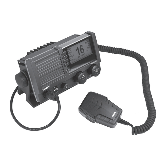
You can use the loudhailer as a 2-way on-board communicator. The loudhailer also functions as a fog horn. You can select from several programmed fog-horn patterns. For a list of other accessories available for the SAILOR 6210 VHF check with your nearest distributor. - Page 12 Chapter 1: Introduction Controls on the front plate 1. Loudspeaker. 2. Four soft keys with function title in the display. 3. Quick selection key for channel 16 and the programmed call channel. 4. Large display. 5. Connector for Handmicrophone or handset. If not used, put the cap from the ACC connector on the front connector to prevent water ingress.
- Page 13 Chapter 1: Introduction SAILOR 6210 VHF display The picture shows the display after start-up.The display holds various fields of information, HI/LO DUAL WATCH depending on the currently WATCH selected function. SCAN 1. Current working channel. MORE... SHIP - SHIP 2. Functions you can select with the soft keys.
- Page 14 Chapter 1: Introduction System configuration - example RX/TX Aerial SAILOR 6201 SAILOR 6204 Handset Control Speaker Microphone SAILOR 6202 Service Hand Microphone Cable SAILOR 6210 SAILOR 6201 Handset Option SAILOR 6207 N163S Connection Box SAILOR 6090 for parallel handsets Power Converter External 12V Battery DSC modem...
-
Page 15: Chapter 2 Operation
Chapter 2 Operation Before using the VHF radio make sure that the VHF antenna, Note power and other external equipment are connected properly. For instructions see chapter Installation on page 27. In this chapter you find detailed instructions and guidelines for: •... -
Page 16: General Use And Navigation
Chapter 2: Operation General use and navigation Power on and speaker volume The VHF radio has a dual-function on/off wheel knob for power on/off and volume control. • To power on the VHF radio press the on/off wheel knob. • To power off the VHF radio, press and hold the on/off wheel knob and follow the instructions in the display. -
Page 17: Adjusting The Squelch
Chapter 2: Operation Speaker devices The VHF radio can be equipped with the following speaking devices: • SAILOR 6202 Handmicrophone with a PTT (Push To Talk) button. • Handset with a microphone, ear piece and a PTT button. The volume in the ear piece can be adjusted, for details see Controller setup on page 8. -
Page 18: Controller Setup
Chapter 2: Operation The functions of the SAILOR 6210 VHF are accessed and set using the four soft keys to the left of the display. The current function of a soft key is shown in the display next to the soft key. For some applications there are two control levels: •... -
Page 19: Vhf Radio Communication
Chapter 2: Operation Parameter Description Handset 1 vol: Adjust earpiece volume for handset 1: OFF, 1 to 14 Note: Default setting is OFF. If a handset is connected to the front connector this value must be configured to a value (1-14). Handset 2 vol: Adjust earpiece volume for handset 2: OFF, 1 to 14 Note: Default setting is OFF. - Page 20 Chapter 2: Operation Basic VHF operation You can make VHF calls using the Handmicrophone or another speaking device. A single, short press on the 16/C key will always bring Note you to channel 16, the international calling and distress channel, no matter what menu the radio is in. Quick guide to radio telephone calls 1.
- Page 21 Chapter 2: Operation 7. Switch to the new channel by turning the selector wheel knob to the agreed channel and begin your conversation. Press PTT only when you are talking. Making a radio telephone call on channel 16 To make a radio telephone call, proceed as follows: 1.
- Page 22 Chapter 2: Operation VHF channels You can change channels whenever the channel designator is displayed. Turn the selector wheel knob to browse through all channels that are available in the selected channel mode. The channels appear in the display in the following order: •...
- Page 23 Chapter 2: Operation Programming a call channel To program a call channel (or quick selection), do as follows: 1. Make an extra-long press (2.5 s duration) on the 16/C key. 2. Press the soft key CALL CH. The channel designator is flashing.
- Page 24 Chapter 2: Operation Display for non-VHF applications When the radio is used for functions other than VHF, the display is arranged differently. The large channel display moves to the bottom line along with selected icons. The channel displayed in this line will always reflect the communication channel on which the radio is tuned into for communication.
-
Page 25: Hi/Lo Transmission Power
Chapter 2: Operation HI/LO transmission power Press the soft key HI/LO to toggle the transmit power between low (1 W) and high (25 W). If LO is not displayed, the transmit power is HI. US channels: Local mode, 10 dB attenuation To attenuate to the incoming signal, do as follows: 1. -
Page 26: Watch
Chapter 2: Operation Watch The SAILOR 6210 VHF radio can be set to dual watch or triple watch. In dual watch, the working channel and channel 16 are watched. In triple watch the working channel, channel 16 and the programmed call channel are watched. -
Page 27: Scan
Chapter 2: Operation Scan The radio has a scanning function for tagged channels. Any available channel, including weather and private channels, can be tagged and added to the scanning sequence. As default the radio scans with priority scanning of channel 16. If a signal is received while in any scanning mode, only channel 16 continues to be watched. - Page 28 Chapter 2: Operation US channels: Watch alarms for NOAA Weather alerts NOAA weather channels are available in the waters of USA and Note Canada only. You can turn on or off an independent watch alarm for a specific weather channel. To turn on or off an independent NOAA weather alarm do as follows: 1.
-
Page 29: Radio Setup
Chapter 2: Operation Radio setup In the RADIO SETUP you set scan and watch mode, select the channel table and can set and view the ATIS code. To change a setting in the RADIO SETUP, do as follows: 1. Press the soft key SETUP. If it is not in the display, press the soft key MORE until SETUP appears. - Page 30 Chapter 2: Operation Para- Description meter Priority ON: All channels tagged for scanning are scanned while monitoring Scan channel 16. (default). OFF: Only the channels tagged for scanning are scanned in sequence, not channel 16, unless it is tagged for scanning. To select the channel table for the primary channel.
- Page 31 Chapter 2: Operation Para- Description meter ATIS The ATIS code (Automatic Transmitter Identification System) is code used for identification to marine coast and inland stations and its use is mandatory in a number of European inland waterways such as e.g. the river Rhine. Like the MMSI number the ATIS number is issued by the relevant authority.
-
Page 32: Loudhailer With Talk-Back
Chapter 2: Operation Loudhailer with talk-back The SAILOR 6210 VHF supports a loudhailer with a talk-back function. When the hailer is in talk-back mode and a radio signal is Important received, the radio signal has a higher priority and is heard in the loudspeaker. -
Page 33: Automatic Foghorn
Chapter 2: Operation Automatic foghorn The SAILOR 6210 VHF has an automatic fog horn application with several foghorn patterns. Once started, it runs in the background while running any other application. The fog horn may be combined with the loudhailer talk- back mode. - Page 34 Chapter 2: Operation 2. Use the selector wheel knob to browse through the patterns available. 3. Press the selector wheel knob at the wanted pattern to accept the pattern. 4. To deactivate the foghorn, turn the selector wheel knob to browse to OFF and press the selector wheel knob.
-
Page 35: Hailer And Fog Horn Setup
Chapter 2: Operation Hailer and Fog horn setup To change a setting in the HAILER/FOGHORN SETUP, do as follows: 1. Press the soft key SETUP. If it is not in the display, press the soft key MORE until SETUP appears. to advance to HAILER/FOGHORN 2. -
Page 36: Replay Function
Chapter 2: Operation Replay function Replay allows the operator to playback received voice messages in the loudspeaker. Recording is activated automatically when a signal is received. Recording is not possible during playback. Up to 60 tracks or 90 seconds can be handled. The recorded channel is displayed. -
Page 37: Chapter 3 Installation
• Installing the VHF radio • Power, VHF antenna and external equipment Unpacking the SAILOR 6210 VHF The following items are included in the delivery of a SAILOR 6210 VHF: • SAILOR 6210 VHF • SAILOR 6202 Handmicrophone with spiral cable •... -
Page 38: Installing The Vhf Radio
Provide space enough to access the front panel connectors and for installing a cradle for the speaking device. Provide at least 120 mm space at the back of the SAILOR 6210 VHF radio to allow free air circulation. Compass safe distance Make sure that the VHF radio is far enough from any magnetic compass to avoid influence of the loudspeaker magnet on the compass reading. - Page 39 Chapter 3: Installation SAILOR 6210 VHF with U mounting bracket The mounting bracket and two knobs are included in the delivery. Desktop mounting Installing the VHF radio...
- Page 40 Chapter 3: Installation Overhead mounting Installing the VHF radio...
- Page 41 Chapter 3: Installation Mounting with U mounting bracket To mount the VHF radio as tabletop, do as follows: 1. Find a suitable location for the VHF radio. Check that the space is wide/deep enough to accommodate the VHF radio. 2. Fasten the bracket with 4 screws (included in the delivery.)
- Page 42 Chapter 3: Installation SAILOR 6210 VHF for flush mount You can mount the VHF radio to a flat surface, e.g. an instrument panel.The flush mount installation kit is included in the delivery. R2.5mm x 4 177mm Remove material from shaded area only! The scaling in the above drawing is not 1:1.
- Page 43 Chapter 3: Installation 1. Find a suitable location for the VHF radio. Check that the space is deep enough to accommodate the VHF radio and an additional min. 120 mm space for cable entry. 2. Keep free distance to allow free air circulation around the VHF radio and to allow sufficient space for access to cables, see the drawing on this page.
- Page 44 Chapter 3: Installation SAILOR 6202 Handmicrophone Handmicrophone with spiral cable and PTT button. Installing the VHF radio...
-
Page 45: Power, Vhf Antenna And External Equipment
Chapter 3: Installation Power, VHF antenna and external equipment 1. ACC connector for accessories 2. CTRL connector for control speaker microphone 3. Power, Loudhailer, foghorn and external speaker 4. VHF antenna 5. Ground stud ACC connector Use the connector marked ACC to connect GPS input. The interface for GPS is NMEA 0183 (EN61 162-1 NMEA0183/ EN61 162-2 NMEA0183 Highspeed). -
Page 46: Pin Description
Chapter 3: Installation Description Wire color NMEA out+ Green Mike 2 / Line in Yellow EAR 2 / Line out Grey Hook_PTT Pink Battery supply when radio is Internal GND = - Battery Black Internal GND = - Battery Orange — SCREEN (Drain) External DSC controller Note... - Page 47 Chapter 3: Installation NMEA interface description NMEA Specifications interface Impedance: 600 Ohm NMEA input: Max. 2mA at min. level of 2V Load Impedance: > 60 Ohm NMEA output Drive load: < 35 mA The NMEA interface supports NMEA 0183 v2.0, v2.1 and v2.3. Power, VHF antenna and external equipment...
- Page 48 Chapter 3: Installation The following sentences are supported: • FSI: All fields are decoded. • GGA: UTC, "Position", "quality indicator" (indicators 1-5). All other fields are unused. • GLL: UTC, "Position", "Status" and "mode" (indicators A and D). All other fields are unused.
- Page 49 Chapter 3: Installation CTRL connector for control speaker microphone Connector type: Circular connector, 12pin. Pin assignment: Connector front view on the VHF radio: Description Description GND for cable screen Internal GND = - Battery Internal GND=- Battery not used Battery supply when radio is on RX out + Battery supply when radio is on 10 RX out - CAN+...
- Page 50 Chapter 3: Installation Power, Loudhailer, foghorn and external speaker Use the connector marked PWR/EXT to connect power, loudhailer and an external speaker. The cable for this connector is part of the delivery. 1. Blue wire: Power - 2. Red isolation on inner connector: loudhailer 3.
- Page 51 Chapter 3: Installation Protection against water ingress You must protect the cable connection with rubber vulcanizing Important tape as shown in the pictures below. This protection prevents water seeping into the VHF radio, cable and connectors. VHF antenna Use the connector marked ANT to connect the VHF antenna to the radio with a 50 Ohm coaxial cable with low loss, e.g.
-
Page 52: System Setup
Chapter 3: Installation System setup To change a setting in the SYSTEM SETUP, do as follows: 1. Press the soft key SETUP. If it is not in the display, press the soft key MORE until SETUP appears. to advance to SYSTEM SETUP. 2. -
Page 53: Sailor 6201 Handset Cradle (Optional)
Chapter 3: Installation SAILOR 6201 Handset cradle (optional) Drilling plan * 120 Space for handset access This Handset has a hook-on/off function, which is activated by a small magnet embedded in the cradle. The cradle must be installed as illustrated in order to ensure the hook-on/off functionality of the Handset. - Page 54 Chapter 3: Installation SAILOR 6201 Handset cradle (optional)
-
Page 55: Chapter 4 Service & Maintenance
Maintenance Preventive maintenance Maintenance of the SAILOR 6210 VHF can be reduced to a maintenance check at each visit of the service staff. Inspect the radio for mechanical damages, salt deposits, corrosion and any foreign material. Due to its robust construction and ruggedness the radio has a long lifetime. -
Page 56: Troubleshooting Guide
Chapter 4: Service & maintenance Troubleshooting guide Action Symptom Remedy The radio will The display is Check if power is present. not turn on empty. Check fuse which is placed in the + supply wire. Check performance of power supply if connected to one. - Page 57 Chapter 4: Service & maintenance Replacing the fuse in the red wire (Power +) One fuse is installed in the supplied DC cable. If the fuse is blown, track down why the fuse was blown and solve the problem. To replace the fuse, do as follows: 1.
-
Page 58: Equipment And Accessories
Chapter 4: Service & maintenance Equipment and accessories SAILOR 6209 Accessory connection box You can use the SAILOR 6209 Accessory Connection Box to combine DSC modem and the SAILOR 6201 Handset option. The wire terminal blocks are connected in parallel. 36090 Warranty For repair or replacement of the VHF radio within terms of warranty,... -
Page 59: Technical Specifications
Appendix A Technical specifications Item Specification Weight SAILOR 6210 VHF approx. 1.2 kg Weight SAILOR 6210 VHF and approx. 1,5 kg including SAILOR 6202 Handmicrophone Handmicrophone and mounting bracket Height: Outer dimension 106 mm, hole Dimensions height for flush mount 89 mm... -
Page 60: Nmea Data Rates And Formats
Appendix A: Technical specifications Item Specification Number of P channels The radio may be programmed with up to 40 private channels that can be managed in all channel modes. Transmit power Hi/Lo: 25 W and <1 W RF output power 25 W +0 dB / - 1.5 dB 1 W +0 dB / - 1.5 dB RF output power, Canada... -
Page 61: Maritime Channels
Appendix B Maritime channels International channels Channels SIMPLEX DUPLEX Channels SIMPLEX DUPLEX Intership Port Port Public Intership Port Port Public 156,050 160,650 156,025 160,625 156,100 160,700 156,075 160,675 156,150 160,750 156,125 160,725 156,200 160,800 156,175 160,775 156 250 160 850 156,250 160,850 156 225 160 825 156,225 160,825... - Page 62 Appendix B: Maritime channels US channels Channels SIMPLEX DUPLEX Channels SIMPLEX DUPLEX Channels 156,050 156,050 162,550 162,400 162,475 156,175 156,175 162,425 156,250 156,250 162,450 156,300 156,300 156,275 156,275 162,500 156,350 156,350 156,325 156,325 162,525 156,400 156,400 156,375 156,375 156,450 156,450 156,425 156,425 156,500 156,500 156,475 156,475...
- Page 63 Appendix B: Maritime channels Ca channels Channels SIMPLEX DUPLEX Channels SIMPLEX DUPLEX Channels 156,050 160,650 156,025 160,625 162,550 156,100 160,700 156,075 156,075 162,400 156,150 160,750 156,125 156,125 162,475 156,200 156,200 156,175 156,175 162,425 156,250 156,250 156,225 160,825 162,450 156,300 156,300 156,225 156,225 162,500 156,350 156,350...
-
Page 64: Private Channels
Appendix B: Maritime channels Bi channels Channels SIMPLEX DUPLEX Channels SIMPLEX DUPLEX Intership Port Port Public Intership Port Port Public 156,050 160,650 156,025 160,625 156,100 160,700 156,075 160,675 156,150 160,750 156,125 160,725 156,200 160,800 156,175 160,775 156,250 160,850 156,225 160,825 156,300 156,300 156,275 160,875 156,350 160,950... -
Page 65: Declaration Of Conformity
Appendix C Declaration of conformity The SAILOR 6210 VHF is certified as stated in the “Declaration of Conformity with R&TTE Directive, enclosed in copy on the next page. - Page 66 Appendix C: Declaration of conformity Thrane & Thrane A/S Declaration of Conformity with R&TTE Directive Equipment included in this declaration Equipment Applicability Declaration Manufacturer Place and Date Svend Åge Lundgaard Jensen · · · · Page 1 of 1 Page 1 of 1...
-
Page 67: Glossary
Glossary Glossary Accessories Automatic Identification System, a short range coastal tracking system used on ships and by Vessel Traffic Services for identifying and locating vessels by electronically exchanging data with other nearby ships. ATIS Automatic Transmission Identification System CTRL Control External NMEA sentence, essential fix data which provide 3D location and accuracy data. - Page 68 Glossary Power NMEA sentence, version of essential gps position, velocity, time data. Very High Frequency NMEA sentence, date and time.
-
Page 69: Index
Index Index Numerics CE, 55 change 16/C, 10 dual and triple watch, 16 90 s replay, 26 channel add to scan, 17 naming, 13 program, 13 remove from scan, 17 ACC connector, 35 select, 6 accessories, 48 working, 6 activate channel table foghorn, 23 ALT, 54... - Page 70 Index contact, 45 foghorn, 1, 23, 24 controls, front plate, 2 activate, 23 cradle for 6201, installation, 43 connector, 40 CTRL connector, 39 patterns, 1 test tone, 24 foghorn frequency, setup, 25 frequency range, VHF, 49 front plate, controls, 2 data rate fuses, how to replace, 47 NMEA, 50...
- Page 71 Index INT, 51 IP rating, 50 NAME, 13 name a call channel, 13 night vision, how to dim, 6 NMEA, 35 key 16/C, 10 data rate, 50 keys on front plate, 2 NMEA input, 42 NMEA interface, 37 NMEA output, 37 LO/HI, 15 LOCAL, 15 loud hailer, 22...
- Page 72 Index replay, 1, 26 soft key button, 2 FOG, 23 reset to default, 42 HAIL, 22 resume time, 19 HORN, 24 RF exposure hazards, iii LOCAL, 15 RTTE, 55 MORE, 8 NAME, 13 OVRIDE, 15 STOP, 26 TAG, 17 safety summary, iii WATCH, 16 salt deposits, 45 WX, 18...
- Page 73 Index temperature water ingress, 50 operational, 49 weather channels, 12 storage, 49 weight, 49 testing, foghorn, 24 wheel knob timeout, 42 selector, 2 triple watch, 19 volume, 2 change to dual, 16 working channel, 6 WX, 18 US, 52 US channel table, 52 antenna cable, 41 antenna connector, 41 channels, 12...
- Page 74 Index...
- Page 76 98-128432-THR-F www.cobham.com/satcom...
Need help?
Do you have a question about the SAILOR 6210 VHF and is the answer not in the manual?
Questions and answers