COBHAM SAILOR 6300 User Manual
Mf/hf dsc 150w/150w fcc/250w/500w
Hide thumbs
Also See for SAILOR 6300:
- User manual (98 pages) ,
- Installation manual (2 pages) ,
- Installation manual (2 pages)
Table of Contents
Advertisement
Advertisement
Table of Contents

Subscribe to Our Youtube Channel
Related Manuals for COBHAM SAILOR 6300


Summary of Contents for COBHAM SAILOR 6300
- Page 1 SAILOR 6300 MF/HF DSC 150W/150W FCC/250W/500W User manual...
- Page 3 SAILOR 6300 MF/HF DSC 150W/150W FCC/250W/500W User manual Document number: 98-131070-THR-E Release date: December 7, 2015...
- Page 4 In the event of any discrepancies, the English version shall be the governing text. Thrane & Thrane A/S is trading as Cobham SATCOM. Copyright © 2015 Thrane & Thrane A/S. All rights reserved. Printed in Denmark.
- Page 5 Write "source for product SAILOR 6300 MF/HF DSC" in the memo line of your payment. This offer is valid to anyone in receipt of this information. http://www.cobham.com/about-cobham/communications-and- connectivity/about-us/satcom/free-and-open-source-software-(foss).aspx You may also find a copy of the source at http://www.thrane.com/foss. This offer is valid to anyone in receipt of this information.
- Page 6 Safety summary The following general safety precautions must be observed during all phases of operation, service and repair of this equipment. Failure to comply with these precautions or with specific warnings elsewhere in this manual violates safety standards of design, manufacture and intended use of the equipment.
- Page 7 RF exposure hazards and instructions Your Thrane & Thrane radio generates electromagnetic RF (radio frequency) energy when transmitting. To ensure that you and those around you are not exposed to excessive amounts of energy and thus to avoid health hazards from excessive exposure to RF energy, all persons must obey the following: Caution! Never touch the MF/HF...
-
Page 8: Emergency Calls
Emergency calls L L L L L if if if if ift C t C t C t Cov ov ov ov over er er er er P P P P P r r r r r e e e e e s s s s s s RED Button s RED Button s RED Button s RED Button... -
Page 9: Manual Overview
SAILOR 6300 MF/HF DSC is designed for occupational use only and must be operated by licensed personnel only. SAILOR 6300 MF/HF DSC is not intended for use in an uncontrolled environment by general public. Manual overview This manual has the following chapters: •... - Page 10 The radio is thus NOT intended for use in an uncontrolled environment by general public. The SAILOR 6300 MF/HF DSC has been tested and complies with the FCC RF exposure limits for Occupational Use Only. The radio also complies with the...
- Page 11 Antenna Safety distance 150W Calculated: 1.71 m or 5.7 feet 250W Calculated: 2.21 m or 7.3 feet 500W Calculated: 3.12 m or 10.3 feet Calculations cover a whip antenna with a maximum gain of 3dBi, worst case frequency (30 MHz), full power and 100% duty cycle (transmitter always on) considering the most conservative limits mentioned in: •...
- Page 12 Related documents Document Title and description number SAILOR 630x MF/HF Control Unit, 98-132396 Installation Guide SAILOR 6300 MF/HF Transceiver Unit 98-133081 & Antenna Tuning Unit 150/250/500 98-144542 W, Installation Guide SAILOR 6000 MF/HF 150/250/500 W 98-130890 System, Installation Manual...
-
Page 13: Table Of Contents
Table of contents Chapter 1 Introduction SAILOR 6301 Control Unit DSC Class A ........1 Accessories available ................6 Chapter 2 Operation Overview ....................11 General use and navigation ............11 Basic MF/HF radio communication .......... 19 Watch function ................... 21 Scan ......................22 DSC calls .................... - Page 14 Table of contents Glossary ........................65 Index ........................67...
-
Page 15: Chapter 1 Introduction
Chapter 1 Introduction SAILOR 6301 Control Unit DSC Class A The SAILOR 6301 Control Unit DSC Class A is a modular and flexible MF/HF radio that can be customized to your specific needs for MF/HF communication on work boats, high seas fishing vessels and merchant vessels of all kinds. -
Page 16: Features
Chapter 1: Introduction Features Rugged and reliable design. Full power range on all ITU channels: 1.6 — 30 MHz for 150 W, 250 W and 500 W systems (Reduced power in the frequency range 1.6 — 4.0 MHz for 500 W according to legislation). Powerful transceiver (150, 250 or 500 W). -
Page 17: System Overview
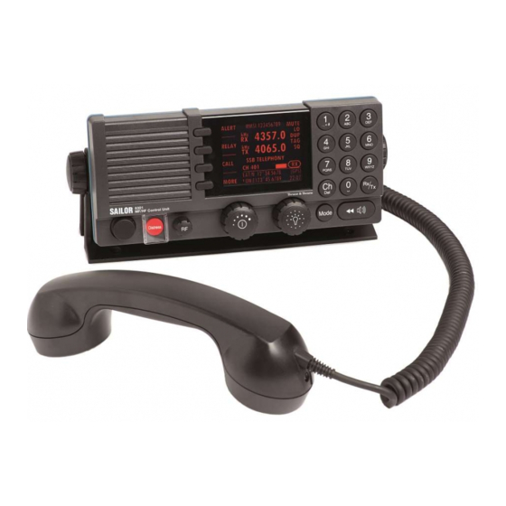
Chapter 1: Introduction System overview The MF/HF radio consists of a Control Unit with a handset, a Transceiver Unit and an automatic Antenna Tuning Unit. The MF/HF radio is available in the following power classes: System sales item numbers 4063xxA-00500 Control Antenna Tuning System... - Page 18 Chapter 1: Introduction Controls on the front 1. Loudspeaker. 2. Four soft keys with function title in the display. 3. Large TFT color display. 4. Alphanumerical keys to enter Rx or Tx frequency or text strings. 5. CH button for channel selection. 6.
-
Page 19: Display Overview
Chapter 1: Introduction Display overview The picture shows the display after start-up. The display holds various fields of information, depending on CALL the currently selected function. 4357.0 kHz/Rx 4065.0 ALERT 1. Functions you can select with kHz/Tx the soft keys. If there are more than 4 functions in the list press DROBOS MMSI: 123456789... -
Page 20: Accessories Available
SAILOR 6201 One SAILOR 6201 Handset with Handset with cradle is included in the delivery of cradle the SAILOR 6300 MF/HF DSC. If needed, you can connect another SAILOR 6201 Handset with cradle. SAILOR 6203 SAILOR 6203 Handset with cradle, Handset with waterproof to IPx6. - Page 21 With the SAILOR 6103 Multi Alarm Panel Multi Alarm Panel GMDSS Distress Alarms can be initiated and monitored. The Multi Alarm Panel is connected to the SAILOR 6300 MF/HF DSC via the Ethernet interface (LAN connector). SAILOR 6081 The SAILOR 6081 Power Supply Unit...
-
Page 22: Transceiver Tt-636Xa And Antenna Tuning Unit Tt-638Xa
Chapter 1: Introduction System configuration - examples Transceiver TT-636xA and Antenna Tuning Unit TT-638xA MF/HF DSC Telex Aerial MF/HF TT-608xA 250W MF/HF with 6 ch. Scanning Power Supply DSC Watch receiver TT-6201A TT-6201A Handset Handset TT-638xA Antenna Tuning TT-636xA Unit Transceiver Unit TT-6209A (Optional) - Page 23 Chapter 1: Introduction Transceivers TT-636xB and Antenna Tuning Unit TT-638xB 250W MF/HF with 6 ch. Scanning TT-608xA DSC Watch receiver Power Supply TT-6201A TT-6201A Handset Handset TT-638xB Antenna Tuning TT-636xB Unit Transceiver Unit TT-6209A (Optional) Accessory TT-630xA TT-6270A MF/HF Control Unit Connection Box Other Alarm (Optional)
- Page 24 Chapter 1: Introduction Accessories available...
-
Page 25: Chapter 2 Operation
Chapter 2 Operation Overview In this chapter you find detailed instructions and guidelines for: • General use and navigation • Basic MF/HF radio communication • Watch function • DSC calls • Handling multiple calls — DSC and voice • Phone book •... - Page 26 Chapter 2: Operation Power on, speaker volume and antenna tuning The MF/HF radio has a dual-function on/off knob for power on/off and volume control. Action Procedure Power on Press the on/off knob. Power off Press and hold the on/off knob and follow the instructions in the display.
- Page 27 Chapter 2: Operation SSB, AM BROADCAST, DSC or TELEX mode Press the Mode button to toggle between modes of the MF/HF radio. • SSB: Upper side band mode used for CALL 4357.0 standard MF/HF telephony. kHz/Rx 4065.0 • AM: AM broadcast is a listen-only mode for ALERT kHz/Tx pleasure purposes except for 2182kHz on...
- Page 28 Chapter 2: Operation For fine tuning of frequencies (voice clarify) press the selector knob. Fine tuning step sizes Selector knob SSB mode AM mode Press 1 x 10 Hz 100 Hz Press 2 x 100 Hz 1000 Hz Press 3 x leave fine- leave fine- tuning...
- Page 29 Chapter 2: Operation Soft-key functions A number of functions of the SAILOR CALL 4357.0 6300 MF/HF DSC are accessed using kHz/Rx the four soft keys to the left of the 4065.0 ALERT display. The current function of a soft kHz/Tx key is shown in the display next to the DROBOS soft key.
- Page 30 Chapter 2: Operation Position and MMSI Information The position and MMSI information for the CALL 4357.0 SAILOR 6300 MF/HF DSC radio is shown in the kHz/Rx lower part of the display. The current (latest) 4065.0 ALERT position of the connected GPS, the UTC and...
- Page 31 Chapter 2: Operation Channel information always available in the display For some functions and for the setup pages, EXIT RADIO SETUP the channel and radiotelephony information Scan Hang Time: OFF Scan Resume: OFF is moved to the bottom section of the Scan Mode: VOICE display.
- Page 32 Chapter 2: Operation Changing the display colors and dim function Red text on black background is available for optimal night vision. To dim the display backlight, e.g. to give comfortable night vision, press, hold and turn the selector knob anti-clockwise. The display shows a brightness bar.
-
Page 33: Basic Mf/Hf Radio Communication
Chapter 2: Operation Basic MF/HF radio communication You can make radio calls using the Handset or another speaker device. • Ship-to-ship communication: Use simplex channels. • Ship-to-shore communication: Use duplex channels. Only valid frequencies and channel numbers are accepted. Selecting SSB telephony frequency 1. - Page 34 Chapter 2: Operation 4. Suggest a frequency pair by saying: “Frequencies [suggested frequencies]” and “Over.” and release the PTT button to allow the caller to confirm the suggested new frequencies. 5. Switch to the new frequencies using the RX/TX button and the keypad and begin your conversation.
-
Page 35: Watch Function
Chapter 2: Operation 4. Say: “This is [your ship’s name]” and “Over.” and release the PTT button to listen. The symbol RX shows that the radio is receiving on the working channel displayed. 5. When answered, agree upon a pair of frequencies, enter the new frequencies or ITU channel and start talking. -
Page 36: Scan
Chapter 2: Operation Scan The radio has a scanning function for tagged voice channels. Any SSB voice channel can be tagged and added to the scanning sequence. In scan mode MULTI, the tagged SSB voice channels and the DSC channel are watched in turn (SSB voice —... -
Page 37: Dsc Calls
Chapter 2: Operation DSC calls In this section of the manual you find information on: • Own Distress — sending, acknowledging and cancelling • Sending a Distress from the SAILOR 6103 Multi Alarm Panel • DROBOS — Distress relay on behalf of someone else •... - Page 38 Chapter 2: Operation 2. Press the soft key FREQ if you want to specify a certain band out of the 6 available as the next distress frequency. Thereafter all 6 distress frequencies are transmitted. 3. Press the soft key VIEW (press MORE to advance to VIEW) to see details and start radio communication on the frequency 2182 kHz (automatically set) to inform about your Distress situation.
- Page 39 Chapter 2: Operation 3. Lift the cover of the red Distress button and push the Distress button for 3 seconds. To receive acknowledgement of own Distress When the MF/HF radio receives an SILENT acknowledgement of Distress from another CALL RECEIVED vessel or station, a 2-tone alarm sounds.
- Page 40 Power failure while in Distress In case of a power failure or switch-off during the transmission of a Distress the SAILOR 6300 MF/HF DSC gives an audible warning after power-up and automatically resumes sending Distress 10 seconds after power up. Within the 10 seconds you have the following options: •...
- Page 41 Chapter 2: Operation 3. Press the MUTE button on the Alarm panel to mute the audible alarm for current distress. All audible alarms are muted. For further information see the Alarm Panel Installation and user manual. DROBOS — Distress relay on behalf of someone else To send a Distress message on behalf of someone else, do as follows: 1.
-
Page 42: Receiving Distress Calls
Chapter 2: Operation Receiving Distress calls When the radio receives a Distress call, the 2-tone alarm sounds. The display shows the bands in which the Distress call is received and the category of the Distress call. The types of Distress calls are Distress, Distress ACK, Distress RELAY and DISTR. - Page 43 Chapter 2: Operation Distress call log As long as you are part of a Distress session, i.e. you have not pressed QUIT, you receive Distress messages and can track all Distress messages for the current Distress event. 1. Press the soft key LOG. If it is not in the display, press the soft key MORE until LOG appears.
- Page 44 4. Press the soft key SEND to make the call. Note Routine calls on e.g. 2177 kHz are not automatically monitored on all radios. Enabling DSC mode on 2177 kHz or dual watch or scan will SAILOR 6300 MF/HF monitor the channel on DSC calls...
- Page 45 Chapter 2: Operation Printing DSC calls If a printer is connected to the SAILOR 6300 MF/HF DSC via LAN you can print DSC messages automatically. You can also print entire DSC call logs. To set up a default printer, do as follows: 1.
- Page 46 Chapter 2: Operation Sessions in the MF/HF radio What is a session? A DSC session is defined as a collection of DSC calls (transmitted and/or received) that are related to the same event (e.g. a Distress event) or established call (e.g. an individual call request followed by an acknowledgement).
- Page 47 Chapter 2: Operation Session state icons Session icons in the session view inform you of the severity or category of the DSC call or Voice communication: • D — Distress category • U — Urgency • S — Safety • R — Routine •...
- Page 48 Chapter 2: Operation Session status The following table gives an overview of the information in the session status: Session status Explanation WAIT FOR You made an individual call to a station and are ACKNOWLEDGE awaiting a reply to establish connection. OCCUPIED The DSC transmission mechanism waits until the selected DSC channel is free.
- Page 49 Chapter 2: Operation Soft key — DSC Radio function session Constructs a reply to the caller if an individual call UNABLE is received which is not compatible with the radio modes. SILENT Silences alarms. Any key silences the alarm but this soft key function will do only this.
- Page 50 Chapter 2: Operation Information for DSC sessions (soft key: VIEW) A DSC session is updated based on DSC calls received or transmitted. Press the soft key VIEW to show the details for the current session. For Distress events a sequence of calls may contribute to the complete view and status of the session.
-
Page 51: Receiving Dsc Calls
See also Display for a session on page 32. Handling multiple calls — DSC and voice The SAILOR 6300 MF/HF DSC can control multiple DSC sessions simultaneously including a voice communication session. All sessions keep track of their session state and the communication channel used. -
Page 52: Phone Book
Chapter 2: Operation In case there are simultaneous alarms, they are sorted according to their priorities, the most important ones are shown first. In some cases alarm or pop-up messages terminate automatically, then the display messages and audible alarms also disappear automatically. Geographical area calls When making a DSC area call, enter the position of the ship (x,y) and the radius... - Page 53 Chapter 2: Operation Using the phone book to make a DSC call To call a contact using the phone book do as follows: 1. Press the soft key CALL. If it is not in the display, press the soft key MORE until CALL appears.
-
Page 54: Editing A Contact
Chapter 2: Operation Contact Description Position For SHIP or COAST STATION: Press and turn the Auto Ack selector knob to select YES or NO for this contact, press the soft key OK. This will allow auto-ack of position requests for this contact. Listen to For GROUP: Press and turn the selector knob to select YES or NO for this contact, press the soft key OK. -
Page 55: Radiotelex
In order to send and receive telex messages press the mode button of the MF/HF radio until TLX-SHIP is shown in the display. For detailed instructions on how to send a radio telex message see the SAILOR 6300 MF/HF Radiotelex, User Manual. Radiotelex... -
Page 56: Replay Function
Chapter 2: Operation Replay function With replay you can playback received voice messages in the loudspeaker. Recording is activated automatically when a signal is received. Recording is not possible during playback. Up to 60 tracks or 240 seconds can be handled. -
Page 57: Setup
Chapter 2: Operation Setup The following setup pages are described in this section of the manual: • Radio setup • Channel setup • Power Supply • DSC setup • DSC call logs • System setup • Controller setup • Diagnostics •... -
Page 58: Radio Setup
Chapter 2: Operation Radio setup Item Description Scan Scan hang time, in seconds on an active receiving working channel. Hang The time is measured from the signal is detected. The radio Time remains on the channel for the set time interval, if a signal was detected. -
Page 59: Power Supply
Chapter 2: Operation Power Supply Item Description Monitor Set this to ENABLED if the radio is connected to a SAILOR 6081 Power Supply Unit and Charger. Set this to DISABLED for any other power supply. Status Visible if ENABLED. Current status of the connected power supply. Voltage Visible if ENABLED. - Page 60 Chapter 2: Operation Item Description Distress Inactivity time-out for received Distress DSC automated Inactivity procedures without automatic time-out: Range: OFF, 1 to 30 minutes, in 1 min. steps Default: OFF Comm Inactivity time-out of non DSC communication. Inactivity Range: 10 to 600 seconds, in 10 s steps Default: 30 s Non- Non-Distress DSC alarms...
-
Page 61: System Setup
Chapter 2: Operation DSC call logs DSC call log Description Received Distress Shows a log of up to 20 received Distress calls. Transmitted Calls Shows a log of up to 20 transmitted calls. Received Calls Shows a log of all received non Distress calls. System setup Item Description... - Page 62 Chapter 2: Operation Item Description Select the position input source GPS Input Automatic: Automatically select position source with the best quality. NMEA TU: Low speed NMEA position input on Transceiver NMEA CU: Low speed NMEA position input on Control Unit LWE1: Specific LWE position input (see LWE Talkers below) LWE2: Specific LWE position input (see LWE Talkers...
- Page 63 Chapter 2: Operation Item Description NMEA in (baud) The actual baud rate of the NMEA input port selected 4800 (only displayed when NMEA TU or NMEA CU is selected) LWE Talkers When Automatic mode is selected updating is shown to indicate the equipment is currently scanning for SAILOR (only displayed 6588 DGNSS devices on the LAN network.
-
Page 64: Controller Setup
Chapter 2: Operation Controller setup Item Description Handset 1 vol: Adjust earpiece volume for handset 1: can be adjusted from 0 to 100, in steps of 5. Note: Default setting is 80. The handset connected to the front connector has top priority and is configured to 80. The volume can be adjusted from 0 to 100, in steps of 5. -
Page 65: System Config
Chapter 2: Operation Diagnostics Item Description Diagnostics In this menu you can view a log with system status messages and you can start a system test of the SAILOR 6300 MF/HF DSC: — Log — System Test — ATU Status —... -
Page 66: Top-Level Soft Key Functions And Setup Pages
Chapter 2: Operation Top-level soft key functions and setup pages TOP LEVEL SOFT KEYS SETUP PAGES CALL EXIT RADIO SETUP Scan Hang Time PHBOOK Scan Resume Scan Mode ALERT EXIT External PTT CHANNEL SETUP Watch Receiver DROBOS EXIT Private Channels PHBOOK DSC Watch HI/LO*... -
Page 67: Chapter 3 Service & Maintenance
Maintenance Preventive maintenance Maintenance of the SAILOR 6300 MF/HF DSC can be reduced to a weekly check and a maintenance check at each visit of the service staff. Inspect the radio for mechanical damages, salt deposits, corrosion and any foreign material. -
Page 68: Salt Deposits
Chapter 3: Service & maintenance Salt deposits Antenna system, including Antenna Tuning Unit, whip antenna, feeder wire and especially supporting isolators should be checked regularly and kept clean to avoid flashovers and reduced output power causing poor radiation. In case the indoor equipment has been exposed to sea water there is a risk of salt crystallization on the keyboard, knobs and cable connectors on the control unit, as well as on cable connectors on the transceiver unit, and they may become inoperable. - Page 69 — including the ability to send or receive a Distress message. Contact your dealer immediately for further advice. The Cobham Test station can be called if physical location and Note weather permits. Select softkey Call. Change Type to Safety Test. Input MMSI: 219015591, select appropriate band and press softkey send.
-
Page 70: Troubleshooting
Chapter 3: Service & maintenance Troubleshooting Action Symptom Remedy If position input source is set to Automatic Position source used position (see System Setup) sentences from the is different following talkers GP, GL, GN (and GA) are from the prioritized. expected Position source is selected by the quality indicator:... - Page 71 Chapter 3: Service & maintenance Action Symptom Remedy Potion The SAILOR 6588 DGNSS Receiver can transmit source position over LAN/LWE. Automatic discovery and selected via selection of up to three (LWE1, LWE2 and LWE3) LAN is SAILOR 6588 DGNSS Receiver source inputs are different supported via SLP.
-
Page 72: Diagnostics
Chapter 3: Service & maintenance Diagnostics Diagnostics In the Diagnostics menu in SETUP the following submenus are available: • Log with system status messages • Self Test • ATU status • ATU RX AMP (MF/HF system 6000A only) Log with system status messages In the Log menu you can view the system status, with time, date and a description (besides a technician code). - Page 73 Chapter 3: Service & maintenance Most of the messages are marked as TU (transceiver unit) or ATU (Antenna Tuning Unit) messages. Text in the Explanation Possible cause(s) display Low Tune Power Too little power reaches Poor antenna installation or the antenna tuner to tune cable properly.
- Page 74 Chapter 3: Service & maintenance Text in the Explanation Possible cause(s) display TU: LO Error Local Oscillator is not Local Oscillator not locked within valid range. ATU: Not Tuned ATU did not find a proper Poor antenna connection matching to the antenna grounding etc.
- Page 75 Chapter 3: Service & maintenance Self Test Two different self tests are available: • Tx single-band transmission test • Tx multi-band transmission test The Tx single Band test performs a tone transmitter test on the current TX frequency shown in the display. Note This test transmits a short test signal at full power —...
- Page 76 Chapter 3: Service & maintenance • ATU SWR ratio. For the tuner, the standing wave ratio of last tune session is recorded (for MF/HF system 6000B only). • ATU TX Relays. For the tuner, the actual settings of relays in the different banks of the tuner are shown.
-
Page 77: Warranty And Returning Units For Repair
Your dealer, installer or Cobham SATCOM partner will assist you whether the need is user training, technical support, arranging on-site repair or sending the product for repair. Your dealer, installer or Cobham SATCOM partner will also take care of any warranty issue. Repacking for shipment Should you need to send the product for repair, please read the below information before packing the product. - Page 78 Chapter 3: Service & maintenance 3. Protect the front- and rear panel with cardboard and insert a layer of shock-absorbing material between all surfaces of the equipment and the sides of the container. 4. Seal the shipping container securely. 5. Mark the shipping container FRAGILE to ensure careful handling. Failure to do so may invalidate the warranty.
- Page 79 Glossary Glossary Amplitude Modulation Antenna Tuning Unit DROBOS Distress Relay On Behalf Of Someone else Digital Selective Calling Forward Error Correction. A system of error control for data transmission, whereby the sender adds redundant data to its messages, also known as an error-correcting code. This allows the receiver to detect and correct errors without the need to ask the sender for additional data.
- Page 80 Glossary International Telecommunications Union Local Area Network LGPL Lesser General Public License Light Weight Ethernet Medium Frequency MMSI Maritime Mobile Ship Identification Single Side Band Standing Wave Ratio Thin Film Transistor. Type of liquid crystal display. Transceiver Unit Coordinated Universal Time defined by ITU...
- Page 81 Index Index buttons description, 4 accessories, 6 acknowledgement, Distress, 25 action line, display, 5 activate CALL, 39 scan resume, 44 call scanning, 22 activate, 37 watch, 21 Distress procedure, vi ACTIVE DSC, 23 activate call, 37 end, 17 session, 32 hold, 37 ADD, 39 quick guide, 19...
- Page 82 Index controls, front plate, 4 DSC, 13 cradle for 6201, installation, 6 background sessions, 37 call log, 29, 47 calls, 23 loopback test, 55 making a call, 29 deactivate multiple calls, 37 watch, 21 self test, 54 default reset, 49 session definition, 32 DELETE, 40 setup, 45...
- Page 83 Index frequencies knob simplex, entering, 13 selector, 4 frequencies, entering, 13 volume, 4 front plate, controls, 4 lock geographical area calls, 38 keys, 50 GPS data, 16 log, 51 GPS position louder, volume, 12 display, 16 maintenance, 53 handset cradle manual, document number, i installation, 6 MAYDAY, vi...
- Page 84 Index multi-band transmission test, 61 printer multiple calls, DSC, 37 DSC messages, 47 mute setup, default, 31 speaker, 14 supported, 47 Printer Config, 31 PTT button, 20 neutral crafts, 46 night vision, how to dim, 13 Non-dist Inactivity, 45 QUIT, 17 Non-distr.alarms, 46 radio call password, 49...
- Page 85 Index scan simplex frequencies add channel, 22 enter, 13 hang time, 44 single-band transmission test, 61 mode, 44 soft key, 15 multi, 44 ADD, 39 remove channel, 22 CALL, 39 resume time, 44 DELETE, 40 resume, activate, 44 DISACK, 28 SSB voice, 15, 44 DSC, 34 start, 22...
- Page 86 Index subcommunication mode, 24 urgency call, 33 telex, 24 Use GPS, 16 voice, 24 UTC time, 5 support, 53 enter manually, 16 SW version, 49 system configuration example, 8 system messages, 51 system overview, 3 system setup, 47 variants, 3 voice call, 33 subcommunication, 24...
- Page 88 98-131070-THR-E www.cobham.com/satcom...
Need help?
Do you have a question about the SAILOR 6300 and is the answer not in the manual?
Questions and answers