Table of Contents
Advertisement
FOR YOUR SAFETY
Do not store or use gasoline or other flammable vapors or
liquids in the vicinity of this or other appliance.
302 Spencer Lane • P.O. Box 5369
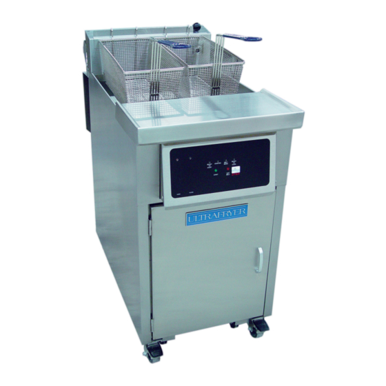
ULTRAFRYER GAS FRYER
MODEL F-P20-18 / 20
OPERATION INSTRUCTIONS
(800) 525-8130 • (210) 731-5000 • Fax: (210) 731-5099
www.ultrafryer.com
WARNING
Improper Installation, adjustment, alteration, service, or main-
tenance can cause property damage, injury, or death. Read the
installation, operating, and maintenance instructions thoroughly
before installing or servicing this equipment.
San Antonio, Texas 78201
30A168
Advertisement
Table of Contents
Troubleshooting

Related Manuals for ULTRAFRYER F-P20-18

Summary of Contents for ULTRAFRYER F-P20-18
-
Page 1: Operation Instructions
ULTRAFRYER GAS FRYER MODEL F-P20-18 / 20 OPERATION INSTRUCTIONS WARNING FOR YOUR SAFETY Improper Installation, adjustment, alteration, service, or main- Do not store or use gasoline or other flammable vapors or tenance can cause property damage, injury, or death. Read the liquids in the vicinity of this or other appliance. - Page 2 PREFACE This Manual was written and published by the Engineering Department, Ultrafryer Systems for use by personnel who will operate a 14” Model PAR-3-H Gas Fryer equipped with an Hard Dock Filtration System in a commercial cooking environ- ment. ENGINEERING DEPARTMENT...
-
Page 3: Table Of Contents
TABLE OF CONTENTS GENERAL INFORMATION PAGE Warranty..............2 Safety . - Page 4 TABLE OF CONTENTS..Continued ELECTRONIC THERMOSTAT CALIBRATION PAGE General ..............21 Electronic Thermostat Calibration .
-
Page 5: General Information
GENERAL INFORMATION Page 1 of 56 30A168... -
Page 6: Warranty
ULTRAFRYER PARTS – All parts on the Ultrafryer® are covered for a period of one (1) year from the initial date of start up. This is to include gas valves, switches, thermostats, etc. Ultrafryer Systems reserves the right to charge for certain parts such as computers, filter pumps and motors or any item over the amount of $100.00 until Ultrafryer Systems receives the defective part... -
Page 7: Safety
Product should always be “PLACED” into the shortening, NOT THROWN. Safety googles, neoprene insulated gloves and an apron must be worn while filtering or boiling-out a fryer vat. Electrical controls on all Ultrafryer Fryers operate on 120 volts single phase electrical power. No adjustments or replacement of electrical controls should ever be attempted without first disconneting electrical power. -
Page 8: Operating Controls Location
E. OPERATING CONTROLS LOCATION 14" MODEL PAR-3-H GAS FRYER Transformer Venturi Hi-Limit Temperature Probe Temperature Control Probe Burner Drain Valve Electric Gas Safety Switch Valve Drain Valve Drain Valve Handle Docking Connection Manual Gas Docking Release Valve Handle Docked Filter Topside Shortening Return Lever (shown Open) -
Page 9: Operating Controls
W.C. ; minimum inlet gas required, orifice size; and type of gas. This data is essential for proper identification when com- nicating with ULTRAFRYER SYSTEMS or requesting special parts or information. The rating plate is located on the inside of the Service Access door. -
Page 10: Inlet Gas Line Sizing
The Flexible Gas Line used to connect the gas manifold to the building gas supply line must be rated for the BTU/Hr (MJ/Hr) designated for the Fryer. Flexible gas lines and their ratings stocked by Ultrafryer Systems are listed below:... -
Page 11: Pre-Installation
PRE-INSTALLATION Page 7 of 56 30A168... -
Page 12: General
A. GENERAL: Safe and satisfactory operation of a Model PAR-3-H gas fryer depends on its proper installation. Installation must conform to local codes or, in the absence of local codes, with the current National Fuel Gas Code ANSI Z223.1 (latest edi- tion). -
Page 13: Receiving & Installing
RECEIVING & INSTALLING Page 9 of 56 30A168... -
Page 14: Unpacking
NOTE: CONNECT-IT inc. 3⁄4" (19mm), 1" (25mm) and 1 1⁄4" (32mm) flexible gas hose 4 feet long (1219mm) with a quick disconnect coupling on one end is available from Ultrafryer Systems under PN 24322 (3⁄4" (19mm) hose), PN 24323 (1" (25mm) hose) and PN 24456 (1 1⁄4" (32mm) hose). These hoses are euipped with a fusible link, which melts at 361°F (183ºC) that will SHUT OFF the gas supply when it melts. -
Page 15: Gas Connection
D. GAS CONNECTION: The gas supply (service) line must be the same size or greater than the inlet line of the appliance. THE GAS SUPPLY LINES MUST BE SIZED TO ACCOMMODATE ALL THE GAS FIRED EQUIPMENT THAT MAY BE CONNECTED TO THAT SUPPLY. -
Page 16: Optional Controls
When the computer is in operation it will DISABLE the fryer if the drain valve is OPENED. Operation of the Ultrastat 11Cooking Computer is covered in the Ultrastat 11 Ultrafryer Computer Operation Instrutction PN 30A053 provided with Fryers equip- ped with that Cooking Computer. - Page 17 LED readout, and display board, the Ultrastat 25 Cooking Computer has been customized for Ultrafryer Systems applications by the addition of up to (10) stage cook- ing profiles for each of the (8) product keys, exit melt feature, optional temp- erature setback and filtering promp, and can be programmed to cook prod- ucts under “Flex”...
-
Page 18: Initial Start-Up
INITIAL START-UP Page 14 of 56 30A168... -
Page 19: Cleaning
Initial calibration or adjustment is the responsibility of the customer and will not be covered by the Ultrafryer Systems warranty. NOTE: Calibration and adjustments must be performed by qualified personnel. -
Page 20: Test Start-Up
TEST START-UP : TO TEST OPERATE an Ultrafryer Gas Fryer equipped with a Default-to-Manual-Restart (DTMR) control: 1) Ensure the fryer’s Toggle ON/OFF Switch is in the OFF position. 2) Fill the fryer vat with hot or cold water to the middle of the “E” in the word LEVEL of the applicable shortening level mark on the rear of the vat. -
Page 21: Optional Cooking Computer
OPTIONAL COOK COMPUTER 1. TO TEST OPERATE a Ultrafryer Gas Fryer equipped with an Ultrastat 11 Cooking Computer, use the procedures contained in the “Ultrastat 11 Gas Fryer Computer Operation Instruction”, PN 30A053, provided with the fryer. 2. TO TEST OPERATE a Ultrafryer Gas Fryer equipped with an Ultrastat 25 Cooking Computer, use the procedures contained in the “Ultrastat 25 Gas Fryer Computer Operation Instruction”, PN 30A051, provided... -
Page 22: Abbreviated Operating Instructions
ABBREVIATED OPERATING INSTRUCTIONS Page 18 of 56 30A168... -
Page 23: General
A GENERAL: This gas fryer is equipped with a shortening filter system which is to be operated and cleaned according to the FRYER OPERATION section of this manual. SHORTENING: Use a high quality shortening to achieve a consistent quality product as well as a long term savings. SHORTENING TEMPERATURE: Most products should be cooked with a shortening temperature about 350˚F (177˚C);... -
Page 24: Electronic Thermostat Calibration
ELECTRONIC THERMOSTAT CALIBRATION Page 20 of 56 30A168... - Page 25 A. GENERAL - If the gas fryer is equipped with an Ultrastat 11, 21, or 25 Cooking Computer, NO maintenance is required on the Temperature Sensing Probe. However, if the fryer is equipped with a Default-to-Manual-Restart (DTMR) Control, the Elec- tonic Thermostat may need to be adjusted or calibrated according to the following procedure: B.
-
Page 26: Preventive Maintenance & Troubleshooting
PREVENTIVE MAINTENANCE & TROUBLESHOOTING Page 22 of 56 30A168... -
Page 27: Preventive Maintenance
Determine that the blower is operating. TROUBLESHOOTING CHART: Should a problem occur that cannot be corrected after performing the above CHECKS, contact an AUTHORIZED repairman and/or Ultrafryer Systems Systems Customer Service 1-800-525-8130 and provide the information acquired while performing these checks. -
Page 28: Troubleshooting Chart
TROUBLESHOOTING CHART ITEM PROBLEMS POSSIBLE SOLUTIONS A. Check the Blower air pressure Switch by temporarily disconnecting the two (2) ORANGE air switch wires and connecting them together. If the IGNITOR sparks when these wires are connected, the air pressure switch is defective and it will Main burner will not ignite. -
Page 29: Cleaning
CLEANING Page 25 of 56 30A168... -
Page 30: Daily
CLEANING - Any item of equipment operates better and lasts longer when it is kept clean and properly maintained. The Gas Fryer is no exception. In order for this fryer to provide years of trouble-free service, it must be CLEANED and MAINTAINED according to instruc- tions herein and at the intervals listed below: TO ASSURE PRODUCING A QUALITY PRODUCT WHILE PROLONGING THE LIFE EXPECTANCY OF WARNING!!! -
Page 31: Cleaning
NOTE: Magnepad Filter Pad not shown c. CLEANING THE FILTER TUB AFTER FILTERING SHORTENING 1) Disassemble the Filter tub by removing the following items in the order listed; 1) FILTER TUB COVER, 2) CRUMB CATCHER SCREEN, 3) FILTER SCREEN W/STANDPIPE/DOCKING attached; then 4) separate the STANDPIPE and DOCKING ASSEMBLY from the Filter Screen. -
Page 32: Weekly
7) CAREFULLY position the FILTER TUB COVER on the OPEN end of the Filter Tub with the SLOT on the cover seated around the Standpipe Handle Docking Assembly. Then, SECURE the cover to the standpipe assembly by locking the latch on the cover. 8) Position the ASSEMBLED Filter Tub in front of the FILTER TUB GUIDES beneath the fryer;... - Page 33 d) Reassemble the “Micro-Mesh stainless steel filter according to DAILY steps 1 c 4) a) (6) . “Magnepad” Envelope Filter – Disassemble, clean, and re-assemble the “Magnepad” Filter Assembly according to DAILY cleaning steps 1 d 2) . Place the CRUMB CATCHER PAN and SLUDGE CATCHER SCREEN in the fryer with the Boil-Out Solution for cleaning, and after they are cleaned, ENSURE they are sprayed with a solution of vinegar/water as described in WEEKLY above.
-
Page 34: Fryer Operation
FRYER OPERATION Page 30 of 56 30A168... -
Page 35: General
A. GENERAL - The “basic” gas fryer is equipped with a Default-to-Manual-Restart (DTMR) Control, which uses an Electronic Thermostat. Some fryers are equipped with an Ultrastat 11,21 or 25 Cooking Computer that use the same Temperature Sensing Probe. In this section, the operation of the gas fryer will cover the Default-to-Manual-Restart (DTMR) Control. NOTE: Refer to Manual PN 30A053, ULTRASTAT 11 Cooking Computer Operating Instruction;... -
Page 36: Dtmr Operation
e. EXIT MELT BUTTON - When this button is momentarily depressed, the melt cycle timing module in the DTMR’s Default-To-Melt circuit will switch to the FULL-ON position allowing the Electronic Thermostat to heat shortening to it’s PRE-SET temperature. DTMR OPERATION - Prior to operating the gas fryer, ENSURE the Filter Tub Assembly is properly installed and DOCKED to the fryer’s Bulkhead socket and the Temperature Control Access Door is closed, the fryer vat is filled with shortening to the middle of the “E”... -
Page 37: Filter Tub Assembly & Installation
FILTER TUB ASSEMBLY & INSTALLATION Page 33 of 56 30A168... - Page 38 FILTER TUB ASSEMBLY - ENSURE all components of the filter tub have been thoroughly cleaned and that the Filter Screen has been assembled according to the CLEANING Section of this manual; then assemble the filter tub as follows: 1. Connect the KNURLED KNOB to the STANDPIPE DOCKING HANDLE ASSEMBLY;...
-
Page 39: Filtering & Polishing Shortening
FILTERING & POLISHING SHORTENING Page 35 of 56 30A168... -
Page 40: Filtering Shortening
A. FILTERING SHORTENING 1. Turn the TOGGLE ON / OFF SWITCH to the fryer OFF, turn the MANUAL GAS VALVE OFF, and ensure the filter tub is properly docked beneath the drain valve. NOTE: Pull on the filter tub Handle to ASSURE the male docking plug is SEATED in the female bulkhead socket. 2. -
Page 41: Polishing Shortening
3) Use the “L” shaped brush to push the sediment through the drain valve to keep the drain clear. Hose off the heat exchanger and vat walls until all sediment and debris has been flushed through the drain into the filter tub. 4) Turn the RIGHT HAND Topside Shortening Return Lever 1⁄4 turn counter clock wise;... -
Page 42: Shortening Disposal, Boil-Out & Installation
SHORTENING BOIL-OUT, DISPOSAL & INSTALLATION Page 38 of 56 30A168... -
Page 43: General
A. GENERAL -The gas fryer should be BOILED-OUT every 7 DAYS to remove carbon buildup and other encrusted material. B. SHORTENING DISPOSAL 1. CAREFULLY assemble and install the Filter Tub assembly according to the instructions in the FILTER TUB ASSEMBLY AND INSTALLATION section. -
Page 44: Boil-Out
When all shortening has been pumped into the rendering tank, TURN the APPLICABLE TOPSIDE SHORTEN- ING RETURN LEVER 1/4 TURN CLOCKWISE, remove the Disposal Hose from the TOPSIDE FEMALE SOCKET. Hang the hose in an upright position so shortening in the hose can drain into a container. 8. - Page 45 SOLID SHORTENING: Cut a block of solid shortening into small pieces. Place small pieces of solid shortening EVENLY on top of the HEAT EXCHANGER TUBES or THOROUGHLY PACK these pieces of solid shortening between, below and above the HEAT EXCHANGER TUBES. While packing solid shortening is messy and time consuming, it is the safest and fastest way to melt solid shortening.
-
Page 46: Technical Assistance
TECHNICAL ASSISTANCE, ORDERING INFORMATION Page 42 of 56 30A168... -
Page 47: Ordering Information
Carriers must be notified immediately and freight inspections must be requested from the carrier. Ultrafryer Systems can and will gladly assist you in prepar- ing and processing of the necessary claims only if proper notification has been accomplished on the carrier deliv- ery document. -
Page 48: Recommended Spare Parts
RECOMMENDED SPARE PARTS Page 44 of 56 30A168... - Page 49 RECOMMENDED SPARE PARTS: To minimize downtime on the Model PAR-3-H gas fryer upon failure of a component part, at least one (1) of the following items should be kept as a spare part in the local area: MODEL PAR-3-H GAS FRYER RECOMMENDED SPARE PARTS LISTING Description Manufacturer’s Part Number...
-
Page 50: Parts Identification
PARTS IDENTIFICATION Page 46 of 56 30A168... - Page 51 PARTS IDENTIFICATION - Locate the part on the following sketches and note the index number i.e, 3, 6, etc; then obtain the part number and description for that index number on the page facing the sketches. Use that part number when ordering a replacement part.
- Page 52 ULTRAFRYER MODEL PAR-3-H GAS FRYER FRONT VIEW � �� �� �� �� � � �� � �� � � � � � � �� � � � � �� Page 48 of 56 30A168...
- Page 53 ITEM DESCRIPTION Drain Clean-out Rod 12569 14" Model PAR-3-H Vat Cover 12A500 Model S87B1008 Spark Ignitor Module 18179 120 Volt to 24 Volt Step-Down Transformer 18180 Drain and Filter Valve Lever Microswitch 18185 Model 39212S-1 Ignitor Rod Cable w/plugs 18187 Electric Gas Combination Control Valve 18227 Electronic Thermostat for use with Default-to-Manual-Restart (DTMR) Control PN 12B014...
- Page 54 ULTRAFRYER MODEL PAR-3-H GAS FRYER REAR VIEW � � � �� � � �� �� ELECTRICAL BOX PN 12A447 �� �� ITEM DESCRIPTION Model SMD 1204 Air Pressure Switch 18A291 Rear Exit Weldment Baffle 19A463 Exhaust Blower Motor Drip Pan 19A527 14"...
- Page 55 � � � � � � ITEM DESCRIPTION Toggle On/Off Switch Guard. 18129 120 Volt 6 Amp SPDT Toggle ON/OFF Switch. 18A287 125 Volt Watt Snaplight w/RED Lens. 23362 Toggle ON/OFF Switch Protective Boot. 23402 125 Volt Watt Snaplight w/AMBER Lens. 23A056 COOKING CONTROLS Default-To-Manual-Restart (DTMR) Control f/ Model PAR-3-H.
- Page 56 PAR-3-H EZ DOCK FILTER TUB ASSEMBLY 14" With Micromesh Filter PN 12B112 14" With Magnepad Filter PN 12B177 � ITEM DESCRIPTION Filter Tub Scraper 12567 � Micromesh S/S Filter Screen Assembly with 12B113 StandPipe & Docking Assembly � Magepad Magnesol Impregnated Filter Pad 12B178 with Standpipe and Docking Assembly Wash Down Hose Assembly...
- Page 57 FILTER SCREEN ASSEMBLY ITEM DESCRIPTION Replacement Frame Set 21A284 Replacement “Upper” Screen 21A285 Replacement Baffle Assembly 21A286 Replacement “Lower” Screen 21A287 � �� � �� � � � �� STANDPIPE CLIP, BAFFLE AND MAGNEPAD ASSEMBLY PN 12B178 ITEM DESCRIPTION 1/2" (13mm) Black Iron Close Nipple 24003 3/8"(10mm) x 7"...
- Page 58 ULTRAFRYER MODEL PAR-3-H GAS FRYER AUTOMATIC VAT CLEANER � � 14” PN 12B157 � � � � � � �� ����� ITEM DESCRIPTION Proximity Actuator Sensor 18A059 Cool II Handle 22734 1⁄2” (13mm) HH-2236 SQ Spray Nozzle 22A111 1⁄2" (13mm) x 90˚ Black Iron Elbow 24007 1⁄2"...
-
Page 59: Wiring Diagrams
WIRING DIAGRAMS Page 55 30A168... - Page 60 WIRING DIAGRAM - Since minor wiring changes may occur in the future, USE the diagram pasted to the fryer for circuit tracing and/or troubleshooting a gas fryer. Page 56 of 56 30A168...
Need help?
Do you have a question about the F-P20-18 and is the answer not in the manual?
Questions and answers