Table of Contents
Advertisement
Quick Links
Advertisement
Table of Contents

Related Manuals for Black Box LR120A


Summary of Contents for Black Box LR120A
- Page 1 LR120A, LR121A, LR122A, LR125A WAN Access Routers Getting Started Guide...
-
Page 2: Compliance Information
AC outlet (such that the computing equipment and receiver are on different branches). CE Notice The CE symbol on your Black Box equipment indicates that it is in compliance with the Electromagnetic Compatibility (EMC) directive and the Low Voltage Directive (LVD) of the European Union (EU). A Certifi- cate of Compliance is available by contacting Technical Support. - Page 3 Trademarks Used In This Manual All applied-for and registered trademarks are the property of their respective owners. Normas Oficiales Mexicanas (NOM) Electrical Safety Statement Instrucciones De Seguridad Todas las instrucciones de seguridad y operación deberán ser leídas antes de que el aparato eléctrico sea operado.
- Page 4 El cable de corriente deberá ser desconectado del cuando el equipo no sea usado por un largo periodo de tiempo. Cuidado debe ser tomado de tal manera que objectos liquidos no sean derramados sobre la cubierta u orificios de ventilación. Servicio por personal calificado deberá...
- Page 5 Ethernet LAN Port ............................34 Serial Port Configuration..........................38 Services..............................45 Security ................................62 DHCP and DNS configuration........................76 IP Services ..............................87 System Configuration.............................90 SNTP Client Configuration ...........................99 System Status..............................102 Specifications ..............................106 Cable recommendations ..........................110 Black Box physical connectors ........................112 Command Line Interface (CLI) Operation ....................117...
-
Page 6: Table Of Contents
Table of Contents Compliance Information ..........................2 Radio and TV Interference ..........................2 CE Notice .................................2 FCC Part 68 (ACTA) Statement (LR120A only) ....................2 Industry Canada Notice ............................2 Summary Table of Contents ..........................5 Table of Contents ............................1 List of Figures ..............................6 List of Tables ..............................8... - Page 7 What you will need ............................23 Interface cable installation ..........................23 Installing an interface cable on the Black Box LR120A’s T1/E1 interface port ..........24 Installing an interface cable on the Black Box LR121A’s X.21 interface port ..........26 Installing an interface cable on the Black Box LR122A’s V.35 interface port ..........28...
- Page 8 WAN Access Routers Getting Started Guide Table of Contents Frame Relay Routed ..............................57 Remote site configuration ..........................57 Central site configuration ..........................60 Security ................................62 Introduction................................63 Configuring the router ............................63 Configuring the security interfaces.........................65 Configuring security policies ...........................66 Deleting a security Policy ..........................67 Enabling the Firewall.............................67...
- Page 9 Power and Power Supply Specifications.......................109 AC universal power supply ........................109 48 VDC power supply ..........................109 Cable recommendations ..........................110 Ethernet Cable ..............................111 Adapter................................111 Black Box physical connectors ........................112 RJ-45 shielded 10/100 Ethernet port........................113 RJ-45 non-shielded RS-232 console port (EIA-561)....................113 Serial port................................114...
-
Page 10: Summary Table Of Contents
WAN Access Routers Getting Started Guide Table of Contents V.35 (M/34 and DB-25 Connector) ......................114 X.21 (DB-15 Connector) ..........................115 E1/T1 (RJ-48C Connector) ..........................116 Command Line Interface (CLI) Operation ....................117 Introduction................................118 CLI Terminology ..............................118 Local (VT-100 emulation) ..........................118 Remote (Telnet) ............................118 Using the Console ............................118 Administering user accounts... -
Page 11: List Of Figures
Black Box front panel LEDs and Console port locations (LR120A shown) ......30... - Page 12 WAN Access Routers Getting Started Guide Define ‘ppp-0’ interface as External ............66 Security Policy Configuration hyperlink .
-
Page 13: List Of Tables
LMI Implementation on the Black Box ........ -
Page 14: About This Guide
About this guide This guide describes installing and configuring Black Box WAN Access Routers High Speed Routers. The instructions in this guide are based on the following assumptions: • The router may connect to a serial DTE device or T1/E1 line •... -
Page 15: Precautions
• Ethernet and serial connections • MDI (LAN connector) • LR121A (X.21)—DB-15 port (DTE) • LR122A (V.35)—DB-25 port (DCE, DTE when using special V.35 cable) • LR120A—T1 configuration. RJ-48C (100-ohm) interface • LR125A—E1 configuration. RJ-48C (120-ohm) and dual-BNC interface (75-ohm) -
Page 16: Typographical Conventions Used In This Document
WAN Access Routers Getting Started Guide Typographical conventions used in this document This section describes the typographical conventions and terms used in this guide. General conventions The procedures described in this manual use the following text conventions: Table 1. General conventions Convention Meaning Futura bold type... -
Page 17: General Information
Chapter 1 General Information Chapter contents WAN Access High Speed Routers overview......................13 General attributes ............................13 Ethernet ................................14 Protocol support .............................14 PPP support ..............................14 WAN interfaces ..............................14 Management ..............................14 Security ................................15 Front panel status LEDs and console port .......................15 Console port .............................16 Rear panel connectors and switches .........................17... -
Page 18: Wan Access High Speed Routers Overview
10/100Base-T Ethernet port, MDI-X cross-over switch, console port, and internal or external power supply. There are three versions in the WAN Access Routers corresponding to a choice of WAN interface: • The LR120A is equipped with an integrated T1/E1 CSU/DSU for connection to full and fractional T1/E1 services. •... -
Page 19: Ethernet
WAN Access Routers Getting Started Guide 1 • General Information Ethernet • Auto-sensing full-duplex 10Base-T/100Base-TX Ethernet. • Standard RJ-45 connector • Built-in MDI-X cross-over switch. • IEEE 802.1d transparent learning bridge. • 2 IP address/subnets on Ethernet interface. Protocol support •... -
Page 20: Security
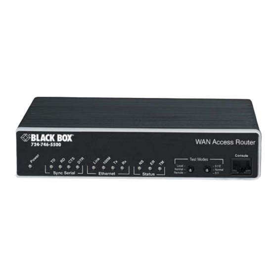
The WAN Access Routers have all status LEDs and console port on the front panel of the unit, and all other electrical connections are located on the rear panel. Figure 1. WAN Access Router (LR120A shown) WAN Access High Speed Routers overview... -
Page 21: Console Port
WAN Access Routers Getting Started Guide 1 • General Information The status LEDs from left to right are (see table 3 for LED descriptions): • Power • Sync Serial TD, RD, CTS, and DTR • Ethernet Link, 100M, Tx, and Rx Table 3. -
Page 22: Rear Panel Connectors And Switches
WAN Access Routers Getting Started Guide 1 • General Information Rear panel connectors and switches On the rear panel from left to right are the following: • Power input connector • Ethernet connector • MDI-X switch • WAN port (V.35, X.21, T1/E1) Power connector AC universal power supply. -
Page 23: Mdi-X
WAN Access Routers Getting Started Guide 1 • General Information MDI-X The MDI-X push switch operates as follows: • When in the default “out” position, the Ethernet circuitry takes on a straight-through MDI configuration and functions as a transceiver. It will connect directly to a hub. •... -
Page 24: Product Overview
Chapter 2 Product Overview Chapter contents Introduction................................20 Applications overview ............................21... -
Page 25: Introduction
The Serial port—Connects to local DTE devices (LR121A and LR122A) • The T1/E1 port—Connects directly to T1/E1 lines (LR120A) the router provides all layer 2 and layer 3 protocols required for end-to-end-link communication. When configuring the WAN Access Router, questions must be answered so the WAN Access Router functions as desired. -
Page 26: Applications Overview
2 • Product Overview Applications overview Black Box’s WAN Access Routers deliver all the advanced features for secure, reliable, and high speed Internet data connections. They combine ease-of-use with powerful data routing to make shared Internet connectivity simple and easy. -
Page 27: Initial Configuration
What you will need ............................23 Interface cable installation ..........................23 Installing an interface cable on the Black Box LR120A’s T1/E1 interface port ..........24 Installing an interface cable on the Black Box LR121A’s X.21 interface port ..........26 Installing an interface cable on the Black Box LR122A’s V.35 interface port ..........28... -
Page 28: Hardware Installation
An WAN Access Router comes with a T1/E1 WAN, V.35, or X.21 interface. Refer to the appropriate section to install an interface cable on your WAN Access Router: • LR120A Router (see “Installing an interface cable on the Black Box LR120A’s T1/E1 interface port” page 24) • LR121A Router (see “Installing an interface cable on the Black Box LR121A’s X.21 interface port”... -
Page 29: Installing An Interface Cable On The Black Box Lr120A's T1/E1 Interface Port
The Black Box Models LR120A and LR125A come with a selectable T1/E1 WAN interface (see figure Located on the back of the Black Box, the T1 and E1 interfaces are presented on an RJ-48C connector with selectable line impedances of 100-ohms for T1 and 120-ohms for E1 lines (see figure... -
Page 30: Rear View Of The Lr125A Showing Location Of Ethernet And Wan Connectors
WAN Access Routers Getting Started Guide 3 • Initial configuration RX connector TX connector (BNC) (BNC) 10/100 Crossover MDI-X Power Ethernet Ethernet connector WAN connector (RJ-45) (RJ-48C) / 1 0 I - X Figure 6. Rear view of the LR125A showing location of Ethernet and WAN connectors The interface cable has been installed, go to section “Installing the AC power cord”... -
Page 31: Installing An Interface Cable On The Black Box Lr121A's X.21 Interface Port
DCE, and a regular straight-through cable can then be used. Do the following to configure the X.21 port as a DCE: 1. Open the Black Box’s case by inserting a screwdriver into the slots and twist the screwdriver head slightly. The top half of the case will separate from the lower half of the case (see figure... -
Page 32: Location Of Dte/Dce Board
WAN Access Routers Getting Started Guide 3 • Initial configuration 2. Locate the small daughter board on the LR121A board to the right of the DB-9 connector (see figure shows location of DTE/DCE daughter board). In this example, the DCE/DTE strap is configured for DCE because the DCE label X.21 connector on the strap is pointed toward the... -
Page 33: Installing An Interface Cable On The Black Box Lr122A's V.35 Interface Port
Figure 11. Connecting the LR122A to a DCE device The serial port on the Black Box LR122A is configured as a DCE; it connects directly to a DTE using a stan- dard straight-through V.35 cable. However, in many applications, the Black Box’s V.35 interface will connect to a DCE (modem or multiplexer), in this situation use the special cable provided with your LR122A. -
Page 34: Installing The Ac Power Cord
AC power cord into the external power supply connector (see figure 12). 2. Insert the female end of the AC power cord into the internal power supply connector (see figure 12). Figure 12. Power connector location on rear panel (LR120A shown) Hardware installation... -
Page 35: Black Box Front Panel Leds And Console Port Locations (Lr120A Shown)
3. Verify that the AC power cord included with your WAN Access Router is compatible with local standards. If it is not, contact Black Box Technical Support to find out how to replace it with a compatible power cord. -
Page 36: Installing The Ethernet Cable
WAN Access Routers Getting Started Guide 3 • Initial configuration Installing the Ethernet cable Do the following: 1. Connect the DB9-RJ45 adapter to the DB-9 serial port on the PC or dumb terminal. Use the RJ45-RJ45 straight-through cable between the adapter and the red marked RJ45 port on the WAN Access Router. 2. -
Page 37: Web Operation And Configuration
1. Launch a standard web browser such as Netscape Communicator or Internet Explorer (IE). 2. Enter the WAN Access Router’s IP address into the URL or Address field of the browser. To see the WAN Access Router home page, refer to the following Figures. LR120A is shown in figure LR121A in figure... -
Page 38: Lr121A Home Page
WAN Access Routers Getting Started Guide 3 • Initial configuration Figure 15. LR121A home page Figure 16. LR122A home page Hardware installation... -
Page 39: Ethernet Lan Port
Chapter 4 Ethernet LAN Port Chapter contents Introduction................................35 LAN connections ............................35 Ethernet Port ..............................35... -
Page 40: Introduction
The secondary IP address must be in the same subnet as the primary IP address. With primary and secondary IP addresses, you can reach the Black Box’s webpages via either IP address. However you will have to login for each separate IP address. -
Page 41: Basic Ethernet Port Attributes
WAN Access Routers Getting Started Guide 4 • Ethernet LAN Port Figure 18. Basic Ethernet port attributes For additional statistical parameters and a few configurable parameters, click on the hyperlink View advanced attributes... (See figure 19.) Figure 19. Advanced Ethernet port attributes The three configurable parameters are all either ‘true’... - Page 42 WAN Access Routers Getting Started Guide 4 • Ethernet LAN Port • Full Duplex Mode: the default value is ‘true’ for Full Duplex operation. Setting it to ‘false’ configures the Ethernet port to operate only in half-duplex mode. Rarely do these parameters require a change from their default operation. Figure 20.
-
Page 43: Serial Port Configuration
Serial interface ..............................39 Variables ..............................39 Web interface configuration ........................40 T1/E1 interface configuration .........................40 Configuring the WAN Access Routers LR120A for T1 operation .............41 Web configuration ..........................41 Configuring the WAN Access Routers LR120A for E1 operation .............42 Web configuration ..........................42 Configuring the WAN Access Routers LR120A for E1 operation .............43... -
Page 44: Wan Serial Port Configuration
WAN services. Below are the configuration options for the WAN interface. Serial interface The serial interface configuration menus allow the user to configure the serial interface for HDLC based con- nections. Variables The following table lists variables that are configurable on the Black Box’s software: Variable Options Function Clock Mode... -
Page 45: Web Interface Configuration
WAN service configuration. T1/E1 interface configuration The WAN Access Routers LR120A is equipped with a user selectable T1/E1 interface. The T1 interface is pre- sented on an RJ-48C (100-ohm) connector, while the E1 interface can use the RJ-48C (120-ohm) or dual BNC (75-ohm) connectors. -
Page 46: Configuring The Wan Access Routers Lr120A For T1 Operation
WAN Access Routers Getting Started Guide 5 • Serial Port Configuration The LR120A T1/E1 serial port configuration page appears in figure Figure 23. LR120A T1/E1 WAN port configuration parameters Configuring the WAN Access Routers LR120A for T1 operation Web configuration. Launch Netscape, Internet Explorer or similar web browser, type the IP address of the... -
Page 47: Configuring The Wan Access Routers Lr120A For E1 Operation
T1 network, set the unit for Receive Recover unless instructed otherwise by your service provider. Idle code: Enabled, Disabled. When enabled, the LR120A inserts idle codes (7E hex) on unused timeslots. Set this option to ‘Disabled’ unless instructed otherwise. -
Page 48: Configuring The Wan Access Routers Lr120A For E1 Operation
FDL Mode: FDL is a T1 application, therefore select ‘Fdl- none’ for E1 applications. Clocking Mode: Options are Internal or Receive Recover Clock (network). In most applications clocking for the LR120A will be derived from the E1 network, set the unit for Receive Recover unless instructed otherwise by your service provider. - Page 49 FDL Mode: FDL is a T1 application, therefore select ‘Fdl- none’ for E1 applications. Clocking Mode: Options are Internal or Receive Recover Clock (network). In most applications clocking for the LR120A will be derived from the E1 network, set the unit for Receive Recover unless instructed otherwise by your service provider.
-
Page 50: Web Configuration
Chapter 6 WAN Services Chapter contents Introduction................................46 PPP Bridged ................................46 Remote site configuration ..........................46 Central site configuration ..........................47 Routed................................48 Remote site configuration ..........................48 Central site configuration ..........................51 LMI Management (Frame Relay links) ........................52 LMI configuration ............................52 Frame Relay Local Management Interface ....................52 LMI Configuration Options ........................53... -
Page 51: Introduction
Remote site configuration The WAN Access Routers can be configured as bridges; in this situation the Black Box typically is at the cus- tomer premise or branch office and connects to a router or bridge at a service provider location (this can be another WAN Access Router). -
Page 52: Central Site Configuration
Create Central site configuration If the central site also has an Black Box, you may configure as described in this section. Refer to the web page images for the Remote Black Box configuration above. In this example, the IP address of interface ip1 is changed to 192.168.100.3/24. -
Page 53: Ppp Routed
First configure the IP address on the Ethernet port (interface ip1) for 192.168.200.2/24 via the command line (CLI). The PC will be on the same subnet as the Black Box Ethernet port. Once this is done, you can complete the configuration using the web pages. -
Page 54: Edit Ip Address Of Wan Port
WAN Access Routers Getting Started Guide 6 • WAN Services – WAN IP address: 192.168.164.2 255.255.255.255 – LLC Header Mode: off – HDLC Header Mode: ON – No authentication – Username: [blank] – Password: [blank] Figure 31. PPP Routed Configuration menu 4. -
Page 55: Configuring The Gateway
WAN Access Routers Getting Started Guide 6 • WAN Services 7. Click on Services Configuration > IP Routes > Create new Ip V4 Route. Create the gateway to the remote router by entering the WAN IP address of the remote router, in this example, enter 192.168.164.3 in the Gateway field. -
Page 56: Central Site Configuration
PC’s IP address is 192.168.172.229/24. Notice that this subnet differs from the subnets of the WAN service link and also the Ethernet port of the remote Black Box (which we just configured). 1. Bring up the web-page management system on your browser by entering the IP address of the Black Box, 192.168.172.3. -
Page 57: Lmi Management (Frame Relay Links)
6. Go to Configuration Menu > Configuration > IP Routes > Click on Create new Ip V4 Route. 7. Create the gateway to the remote Black Box by entering the WAN IP address of the remote Black Box, in this example, enter 192.168.164.2 in the Gateway field 8. -
Page 58: Lmi Configuration Options
WAN Access Routers Getting Started Guide 6 • WAN Services LMI Configuration Options The Frame Relay Local Management Interface is configurable through either the CLI or web interface on the WAN Access Routers. The following variables are available for configuration. •... -
Page 59: Web Configuration Methods
192.168.200.2/24. The PC must be on the same subnet for configuring the Black Box via the web pages. 1. Bring up the web-page management system on your browser by entering the IP address of the Black Box. Frame Relay bridged... -
Page 60: Frame Relay Bridged Creation
WAN Access Routers Getting Started Guide 6 • WAN Services 2. On the Menu, go to Services Configuration, then to WAN. Delete the factory default WAN services already defined. 3. Click on Create a new service in the main window, select “Frame Relay bridged” and click on Continue. 4. -
Page 61: Central Site Configuration
Black Box via the web pages. 1. Bring up the web-page management system on your browser by entering the IP address of the Black Box. 2. On the Menu, go to Services Configuration, then to WAN. Delete the factory default WAN services already defined. -
Page 62: Frame Relay Routed
This conclude the central site configuration. Frame Relay Routed This application shows the configuration for two Black Box units in routed mode. If using a third party router at the Central site, review the router’s configuration for connection to a remote bridge. - Page 63 WAN Access Routers Getting Started Guide 6 • WAN Services 4. Enter the description for the circuit in the Description field. This is a mandatory field. Without a descrip- tion you cannot create a WAN service. (See figure 40.) Figure 40. Frame Relay routed configuration –...
- Page 64 2. Click on System Configuration > IP Routes > Create new Ip V4 Route 3. Create the gateway to the remote Black Box by entering the WAN IP address of the remote Black Box, in this example, enter 192.168.164.3 in the Gateway field.
-
Page 65: Central Site Configuration
First configure the IP address of the Black Box’s Ethernet port (interface ip1) via the command line (CLI) for 192.168.172.3/24. The PC must be on the same subnet for configuring the Black Box via the web pages. - Page 66 2. Click on System Configuration > IP Routes > Create new Ip V4 Route 3. Create the gateway to the remote Black Box by entering the WAN IP address of the remote Black Box, in this example, enter 192.168.164.3 in the Gateway field.
-
Page 67: Security
Chapter 7 Security Chapter contents Introduction................................63 Configuring the router ............................63 Configuring the security interfaces.........................65 Configuring security policies ...........................66 Deleting a security Policy ..........................67 Enabling the Firewall.............................67 Firewall Portfilters ..............................68 Security Triggers..............................69 Intrusion Detection System (IDS) .........................70 Introduction to NAT ............................73 Enabling NAT ..............................73 Global address pool and reserved map... -
Page 68: Introduction
WAN Access Routers Getting Started Guide 7 • Security Introduction Security provides the ability to setup and enforce security policies. The policies define the types of traffic per- mitted to pass through a gateway, either inbound, outbound, or both, and from which origins the traffic may be allowed to enter. -
Page 69: Ppp Routed Wan Service For Security Firewall Example
The next step in configuring the router is to add the default gateway route. The WAN IP address of the routed PPP WAN service at the CO site is 192.168.101.2, so this will be the gateway IP address on the Black Box. -
Page 70: Configuring The Security Interfaces
WAN Access Routers Getting Started Guide 7 • Security 4. Leave Destination and Netmask both as 0.0.0.0 because this is the gateway default route. 5. Click on the Update button. 6. Seeing the green check mark under Valid indicates the IP addresses of the WAN service and the gateway are properly configured. -
Page 71: Configuring Security Policies
WAN Access Routers Getting Started Guide 7 • Security 2. Go to the third section (Security Interfaces) on the Security Interface Configuration webpage. Click on the hyperlink Add interface... 3. Select ip1 beside the Name pull-down menu, and select internal beside the Interface Type pull-down menu. Click on Create. -
Page 72: Deleting A Security Policy
WAN Access Routers Getting Started Guide 7 • Security Figure 49. Security Policy Configuration hyperlink 2. Click on the hyperlink New Policy... (See figure 50.) Figure 50. New Policy link to configuration webpage 3. Select the parameters so the policy is defined as follows: Between interfaces of types: external internal Validators will allow traffic. -
Page 73: Firewall Portfilters
WAN Access Routers Getting Started Guide 7 • Security 1. Return to the Security page. 2. Under Security State select Enabled for Security. Click on Change State. 3. Next select Enabled for Firewall. Click on Change State. The network is now secure. All the interfaces which have been defined are protected and all traffic is blocked between different the different interface types. -
Page 74: Security Triggers
WAN Access Routers Getting Started Guide 7 • Security Figure 52. Defining ICMP port filter for ping You can now ping between the two networks Security Triggers Security triggers are used to allow an application to open a secondary port in order to transport data. The most common example is FTP. -
Page 75: Intrusion Detection System (Ids)
WAN Access Routers Getting Started Guide 7 • Security 2. Set the parameters as follows (See figure 54.): – Transport Type = tcp – Port Number Start = 21 – Port Number End = 21 – Allow Multiple Hosts = Block –... - Page 76 WAN Access Routers Getting Started Guide 7 • Security Attacking Host Attack Name Protocol Blacklisted? SYN/FIN/RST Flood TCP If scanning threshold exceeded Net Bus Scan Back Orifice Scan 1. To enable IDS, click on Enabled for “Intrusion Detection Enabled” on the “Security Interface Configura- tion”...
- Page 77 WAN Access Routers Getting Started Guide 7 • Security – Once the maximum number of unfinished TCP handshaking sessions is reached, an attempted DOS attack is detected. The firewall blocks the suspected attacker for the time limit specified in the DOS Attack Block Duration parameter.
-
Page 78: Introduction To Nat
WAN Access Routers Getting Started Guide 7 • Security Introduction to NAT The basic steps for configuring NAT are: 1. Enable NAT between the internal and external interfaces of the firewall. 2. Create global addresses which will be added to the global pool of IP addresses on the WAN interface. 3. - Page 79 WAN Access Routers Getting Started Guide 7 • Security 3. Set the parameters to the following values (See figure 55.): – Interface Type: internal – Use Subnet Configuration: Use IP Address Range – IP Address: 100.100.100.101 – Subnet Mask/IP Address 2: 100.100.100.102 Click on Add Global Address Pool button.
- Page 80 WAN Access Routers Getting Started Guide 7 • Security Figure 56. NAT Reserved mapping configuration The PC on the Ethernet side of the Black Box can now communicate with the ‘public’ or ‘global’ side through NAT. Introduction to NAT...
-
Page 81: Dhcp And Dns Configuration
Chapter 8 DHCP and DNS configuration Chapter contents Introduction................................77 Services and features normally associated with each other ................77 DHCP Server ..............................78 Parameters for the DHCP Server subnet ....................80 IP Addresses to be available on this subnet ....................81 DNS server option information .........................82 Default gateway option information ......................82... -
Page 82: Introduction
8 • DHCP and DNS configuration Introduction The routers offer a DHCP Server, DHCP Relay capability, and DNS Relay incorporated into the Black Box. Of the two DHCP features, only one can be enabled at a time-either DHCP server or DHCP relay. -
Page 83: Dhcp Server
• When DHCP Relay is used with a Bridged WAN service, the DHCP server must be on the same subnet as the clients and the Black Box. DHCP Server Go to the DHCP Server webpage from the Configuration Menu --> Services Configuration --> DHCP Server. -
Page 84: Dhcp Server Web Page
WAN Access Routers Getting Started Guide 8 • DHCP and DNS configuration Figure 57. DHCP Server web page The server needs to have a subnet of IP addresses which will be allocated when a DHCP client makes a request. Define the subnet by clicking on the hyperlink Create new Subnet... The next webpage, Create new DHCP Server subnet has four sections. -
Page 85: Parameters For The Dhcp Server Subnet
WAN Access Routers Getting Started Guide 8 • DHCP and DNS configuration Figure 58. DHCP server configuration web page Parameters for the DHCP Server subnet Four parameters are in the section for defining the DHCP subnet. (See figure 59.) Figure 59. DHCP Server subnet parameters The first two parameters are applicable when you will define the subnet. -
Page 86: Ip Addresses To Be Available On This Subnet
Get subnet from IP interface: If you use this option, then you will not enter any values in the first two parameters. Should you define another subnet and also select Get subnet from IP interface, the Black Box uses the Get subnet from IP interface as the ruling parameter and sets Subnet value and Subnet mask appropri- ately, overriding your initial selection. -
Page 87: Dns Server Option Information
DNS server. The WAN Access Router merely forwards the packet. The third parameter is ‘Use local host address as DNS server’ which is the IP address of the Black Box. In this scenario, the client considers the Black Box as a DNS server by sending all requests to the Black Box’s IP address. -
Page 88: Additional Option Information
With this webpage, you can enter a list of IP addresses for DHCP servers. When a client requests an IP address, it uses one of the DHCP addresses listed in the DHCP relay webpage. The Black Box forwards (or ‘relays’) the request to the DHCP server. -
Page 89: Dhcp Relay Webpage
WAN Access Routers Getting Started Guide 8 • DHCP and DNS configuration In the first section of the DHCP Relay webpage, click on the Enable button on the DHCP Relay webpage. Figure 64. DHCP Relay webpage In the third section of the DHCP Relay webpage, enter the IP address of a DHCP server, and click on the Cre- ate button. -
Page 90: Dns Relay
8 • DHCP and DNS configuration DNS Relay The DNS Relay webpage contains a configurable list of DNS server IP addresses. The Black Box’s DNS Relay forwards DNS queries from a client to a pre-defined DNS server and DNS server responses to the client. - Page 91 WAN Access Routers Getting Started Guide 8 • DHCP and DNS configuration Enter the IP address of the primary DNS server (see figure 67) and click on the Create button. Similarly enter the IP address of the secondary DNS server. Figure 67.
-
Page 92: Ip Services
Chapter 9 IP Services Chapter contents Introduction................................88 Server................................88 CLI Configuration ............................88 Associated Ports for the different System (IP) Services ..................89... -
Page 93: Introduction
The System Service which must be wisely disabled is the WEB Server. After you disable the WEB Server from the web page, you can no longer access the any of the Black Box’s web pages. The only way to enable it is through the Command Line Interface (CLI). -
Page 94: Associated Ports For The Different System (Ip) Services
WAN Access Routers Getting Started Guide 9 • IP Services Associated Ports for the different System (IP) Services This section is for information purposes only. Consult the table to identify which ports are associated with the different System (IP) Services. Table 6. -
Page 95: System Configuration
Chapter 10 System Configuration Chapter contents Introduction................................91 Detailed Description .............................91 Authentication ..............................91 Alarm ................................92 Remote Access ..............................94 Update ................................94 Save ................................95 Backup/Restore ...............................95 Restart ................................96 Website Settings .............................96 Error Log ................................97 SNMP Daemon ..............................97 System Tools ..............................98... -
Page 96: Introduction
Alarm: shows the Alarm Table and CPU Usage Settings. You can configure the alarm severity for each of the alarms and enable/disable the Alarm Error Log. • Remote Access: enable and set the time limit for a remote user to have access to the Black Box. • Update: update the Black Box software from here. -
Page 97: Alarm
• creating a Username • defining the Password • give the user ability to configure the Black Box or read-only authority • add a comment useful to the administrator Figure 71. Creating new user Alarm Access the configuration and status of the alarms. - Page 98 10 • System Configuration All Black Box routers have the ‘PP over Threshold’ and ‘NP over Threshold’ alarms. The LR120A has addi- tional alarms for the T1/E1 WAN port. An alarm can be tested by clicking on the Generate button. Similarly, by clicking on the Clear button, the alarm is cleared, that is, turned off, however the Time and Count parame- ters remain.
-
Page 99: Remote Access
74). The length of access over a remote connection is set on this webpage. If set for zero (0), no user can access the Black Box remotely. How- ever if a user is authorized for access, then the time is the limit before the remote access session is closed. -
Page 100: Save
76.) If you do not do this, all configuration changes are stored only in volatile memory, meaning that if the Black Box is restarted, all configuration changes are lost. Click on the Save button and wait until seeing the message Saved information model to im.conf. -
Page 101: Restart
10 • System Configuration Restart From this webpage, you can do a soft reboot of the Black Box or restore the Black Box to factory defaults. To restore to factory defaults, click on the box for Reset to factory default settings. (See figure... -
Page 102: Error Log
The Community Table has three configurable parameters. • Password: this is the password which the remote management station must use to access the Black Box for reading/writing the SNMP variables. • Management IP: the IP address of the management station. -
Page 103: System Tools
WAN Access Routers Getting Started Guide 10 • System Configuration To delete an entry, click on the Del box (see figure 81) and click on the Update button. Figure 81. SNMP Daemon configuration The Trap Table identifies the IP address of the SNMP trap along with its Password. System Tools The System Tools webpage provides two utilities for testing network connectivity. -
Page 104: Sntp Client Configuration
Chapter 11 SNTP Client Configuration Chapter contents Introduction................................100 Configuring the SNTP client ..........................100 SNTP Client Mode Configuration Parameters .....................100 SNTP Client General Configuration Parameters ..................101 System Clock Setting............................101... -
Page 105: Introduction
Anycast is a multipoint-to-point mode. Broadcast mode is for use when the SNTP server is on the local network, that is, the same subnet as the Black Box. When Unicast mode is enabled, the Black Box sends a request to the server designated in the field containing the SNTP server’s IP address. (See figure... -
Page 106: Sntp Client General Configuration Parameters
Figure 85. Configuration of the internal system calendar clock After entering the system clock values, click on the Set Clock button to save in volatile memory. If the Black Box is rebooted, either soft or by power-cycling, the Clock Setting returns to its default value. System Clock Setting... -
Page 107: System Status
Chapter 12 System Status Chapter contents System Status...............................103 Port Connection Status ..........................103 LAN Status ..............................104 WAN Status ..............................104 Hardware Status ............................104 Defined Interfaces ............................104 Status LEDs.................................105... -
Page 108: System Status
12 • System Status System Status A quick but thorough summary of the Black Box’s status is provided on this webpage, but it also has links to the detailed webpages for the key subsystems of the Black Box. The webpage is divided the following sections: •... -
Page 109: Lan Status
• Current Time: the time is derived from one of two sources. If the Black Box is configured as an SNTP cli- ent, the time is from an SNTP server. If the SNTP client is not configured, the time derives from the Clock Setting as set by the user. -
Page 110: Status Leds
WAN Access Routers Getting Started Guide 12 • System Status Status LEDs The LEDs indicate the status of the Power, the WAN, Sync Serial port, and the Ethernet connection. All LED indicators will present the same looking profile (e.g., clear) when unlit due to being single color, water clear, high efficiency LEDs. - Page 111 Appendix A Specifications Chapter contents General Characteristics ............................107 Ethernet ................................107 Sync Serial Interface ............................107 T1/E1 Interface ..............................107 Protocol Support ..............................107 Support................................108 Management ...............................108 Security ................................108 Compliance Standard Requirements........................109 Australia Specific .............................109 Dimensions .................................109 Power and Power Supply Specifications.......................109 AC universal power supply ........................109 48 VDC power supply ..........................109...
-
Page 112: A Specifications
WAN Access Routers Getting Started Guide A • Specifications General Characteristics • Compact low-cost router/bridge • 10/100 Ethernet • Comprehensive hardware diagnostics. Easy maintenance and effortless installation. • Built-in web configuration. • Setup allows for standard IP address and unique method for entering an IP address and mask WITHOUT use of a console connection. -
Page 113: Ppp Support
WAN Access Routers Getting Started Guide A • Specifications • Built-in ping and traceroute facilities. • Integrated DHCP Server (RFC 2131). Selectable general IP leases and user specific MAC/IP pairings. Selectable lease period. • DHCP relay agent (RFC 2132/RFC 1542). •... -
Page 114: Compliance Standard Requirements
WAN Access Routers Getting Started Guide A • Specifications • Access list determining up to 5 hosts/networks which are allowed to access management system SNMP/ HTTP/TELNET. • Logging or SMTP on events: POST, POST errors, PPP/DHCP, IP. Compliance Standard Requirements •... -
Page 115: Cable Recommendations
Appendix B Cable recommendations Chapter contents Ethernet Cable ..............................111 Adapter................................111... -
Page 116: Ethernet Cable
WAN Access Routers Getting Started Guide B • Cable recommendations Ethernet Cable Ethernet cable (P/N 10-2500) (refer to “RJ-45 shielded 10/100 Ethernet port” on page 113) Adapter EIA-561 to DB-9 (P/N 16F-561) (refer to “RJ-45 non-shielded RS-232 console port (EIA-561)” on page 113) Ethernet Cable... -
Page 117: C Black Box Physical Connectors
Appendix C Black Box physical connectors Chapter contents RJ-45 shielded 10/100 Ethernet port........................113 RJ-45 non-shielded RS-232 console port (EIA-561)....................113 Serial port................................114 V.35 (M/34 and DB-25 Connector) ......................114 X.21 (DB-15 Connector) ..........................115 E1/T1 (RJ-48C Connector) ..........................116... -
Page 118: Rj-45 Shielded 10/100 Ethernet Port
Direction Output Output Input Input RJ-45 non-shielded RS-232 console port (EIA-561) The RS-232 serial control port of the Black Box is configured to operate as a DCE. Table 9. RS-232 Control Port Pin No. Signal Name Direction Output Output Input... -
Page 119: Serial Port
WAN Access Routers Getting Started Guide C • Black Box physical connectors Serial port V.35 (M/34 and DB-25 Connector) The LR122A has a DB-25 connector for the V.35 interface. table 10 provides the pinouts for the M/34 and DB-25 connectors. -
Page 120: Connector)
WAN Access Routers Getting Started Guide C • Black Box physical connectors X.21 (DB-15 Connector) The X.21 interface in the LR121A may be configured for either DTE or DCE. Default is DCE. Table 11. X.21 Interface (LR121A) Pin No. Circuit... -
Page 121: E1/T1 (Rj-48C Connector)
WAN Access Routers Getting Started Guide C • Black Box physical connectors E1/T1 (RJ-48C Connector) The T1/E1 transmit signals are not polarity sensitive, even though they have the traditional designation of Tip and Ring. Table 12. T1/E1 Port Pin No. -
Page 122: D Command Line Interface (Cli) Operation
Appendix D Command Line Interface (CLI) Operation Chapter contents Introduction................................118 CLI Terminology ..............................118 Local (VT-100 emulation) ..........................118 Remote (Telnet) ............................118 Using the Console ............................118 Administering user accounts ..........................120 Adding new users ............................120 Setting user passwords ...........................121 Changing user settings ..........................121 Controlling login access ..........................121 Controlling user access... -
Page 123: Introduction
WAN Access Routers Getting Started Guide D • Command Line Interface (CLI) Operation Introduction The modem configuration and status can also be view and modified through the console, which is accessible through the RS-232 serial port or through a Telnet session over Ethernet. CLI Terminology In order to use the CLI commands, you need to understand the following CLI terms: •... - Page 124 WAN Access Routers Getting Started Guide D • Command Line Interface (CLI) Operation By entering a keyword followed by a space and “?” the options available will print immediately without press- ing enter. The previously entered commands are reprinted on the next lines. For example: →...
-
Page 125: Administering User Accounts
WAN Access Routers Getting Started Guide D • Command Line Interface (CLI) Operation ip interface ip1 list secondaryipaddresses <enter> Secondary IP addresses for interface: ip1 ID | IP Address -----|----------------- ----------------------- In this example there was not a secondary IP address. Now save the entire configuration in nonvolatile FLASH mem- ory with the following command. -
Page 126: Setting User Passwords
WAN Access Routers Getting Started Guide D • Command Line Interface (CLI) Operation Setting user passwords To change the password for the user you are currently logged in as, use the command: user password Enter the new password twice as prompted: Enter new password: *** Again to verify: *** →... - Page 127 © Copyright 2006. Black Box Corporation. All rights reserved. Released: April 19, 2006 1000 Park Drive • Lawrence, PA 15055-1018 • 724-746-5500 • Fax 724-746-0746...
Need help?
Do you have a question about the LR120A and is the answer not in the manual?
Questions and answers