Table of Contents
Advertisement
Quick Links
Service
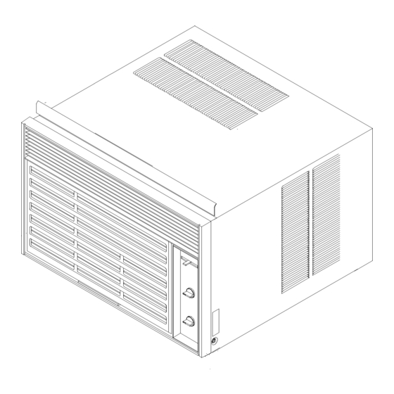
International Compact Room Air
Conditioners
Service manual for
AmanaÒ
This manual to be used by qualified appliance
technicians only. Amana does not assume any
responsibility for property damage or personal
injury for improper service procedures done by
an unqualified person.
Raytheon Appliances
Base manual covers
general information on
Room Air Conditioners.
Refer to individual
technical sheets for
information on specific
models
RS5100002
Revision 0
July 1997
Advertisement
Table of Contents

Subscribe to Our Youtube Channel
Related Manuals for Amana 10c5ez


Summary of Contents for Amana 10c5ez
- Page 1 International Compact Room Air Conditioners Service manual for AmanaÒ This manual to be used by qualified appliance technicians only. Amana does not assume any responsibility for property damage or personal injury for improper service procedures done by an unqualified person. RS5100002...
-
Page 2: Table Of Contents
Table of Contents Performance Tests Important Information Performance Tests ..........28 Important Notices for Consumers and Servicers .. 3 Cooling Performance Test ........28 Recognize Safety Symbols, Words, and Labels ... 3 Cooling Wattage Consumption Test ..... 30 Important Safety Information Performance Test Diagnosis Guide ...... -
Page 3: Important Information
(such as exposure to electrical shock) may result. CAUTION Amana will not be responsible for any injury or property damage from improper service procedures. If performing service on your own product, you assume all responsibility for any personal injury or property... -
Page 4: Important Safety Information
It is This Service Manual describes the operation, extremely important to replace all removed earthing disassembly, troubleshooting, and repair of Amana wires before completing service. Room Air Conditioners. It is intended for use by... -
Page 5: Product Identification
Product Identification Every Amana Room Air Conditioner has an identification Fan motors are sealed to prevent moisture and dirt plate showing the model number, P (manufacturing part) contamination of motor windings. Motor bearings are number, serial number, etc. of unit. Identification plate is permanently lubricated. -
Page 6: Installation Instructions
Do not bend or trim power The following paragraphs describe how to properly install prongs on plug to make them fit a receptacle for an Amana Room Air Conditioner. Before attempting to which they are not intended. install the unit: For your personal safety, air conditioner must be earthed. -
Page 7: Preparing For Installation
General Through-Wall Installation for Slide Out Chassis Model CAUTION Amana Room Air Conditioners with slide out chassis type cases are designed to be installed through a wall or To avoid risk of personal injury or product damage: in a window. The following instructions describe general •... -
Page 8: Brick Veneer Or Frame Wall Construction
Installation Instructions General Instructions Brick Veneer or Frame Wall Construction A finished opening in wall is required. Dimensions of A framed, finished opening 62 cm wide X 42 cm high opening are 62 cm wide X 42 cm high. The lower right high should be cut out or built into wall. -
Page 9: Installation In Walls Exceeding 27 Cm
Installation Instructions Installation in Walls Exceeding 27 cm 1.3 cm Inside wall All air conditioner models have side louvers on outer case. When air conditioner is installed in walls over Wall stud or framing 27 cm Caulk 27 cm thick, provisions must be made in the wall opening Mortar to allow unobstructed air flow to the side louvers. -
Page 10: Operating Instructions
Operating Instructions Air Conditioner Controls There are three types of air conditioner control panels available: a touch control, a rotary control, and an alternate rotary control. CLOSED EXHAUST VENT CONTROL FAN CONTROL CLOSED EXHAUST COOL COOL VENT CONTROL HIGH FAN CONTROL COOL HIGH COOL... -
Page 11: Initial Start Up
Operating Instructions Control settings of 3 and below are ECONOMY Fan Control SETTINGS . Setting control in this range can result in The FAN CONTROL controls operation of indoor fan. energy savings by reducing amount of time compressor This fan circulates air in area being cooled. operates (because room or area is not being cooled as much as with higher settings). -
Page 12: Care And Maintenance
The fan motor is permanently lubricated. Additional lubrication should never be applied. Contact an To avoid risk of electrical shock, personal injury, or authorized Amana Service Center if fan malfunctions in death, disconnect electrical power to unit before any manner. -
Page 13: Troubleshooting Information
Troubleshooting Information WARNING To avoid risk of electrical shock, personal injury, or death, disconnect electrical power source to unit and discharge capacitor through a 10,000 ohm resistor before attempting to service, unless test procedures require power to be connected. Ensure all earth wires are connected before certifying unit as repaired and/or operational. - Page 14 Troubleshooting Information WARNING To avoid risk of electrical shock, personal injury, or death, disconnect electrical power source to unit and discharge capacitor through a 10,000 ohm resistor before attempting to service, unless test procedures require power to be connected. Ensure all earth wires are connected before certifying unit as repaired and/or operational.
- Page 15 Troubleshooting Information WARNING To avoid risk of electrical shock, personal injury, or death, disconnect electrical power source to unit and discharge capacitor through a 10,000 ohm resistor before attempting to service, unless test procedures require power to be connected. Ensure all earth wires are connected before certifying unit as repaired and/or operational.
- Page 16 Troubleshooting Information WARNING To avoid risk of electrical shock, personal injury, or death, disconnect electrical power source to unit and discharge capacitor through a 10,000 ohm resistor before attempting to service, unless test procedures require power to be connected. Ensure all earth wires are connected before certifying unit as repaired and/or operational.
- Page 17 Troubleshooting Information WARNING To avoid risk of electrical shock, personal injury, or death, disconnect electrical power source to unit and discharge capacitor through a 10,000 ohm resistor before attempting to service, unless test procedures require power to be connected. Ensure all earth wires are connected before certifying unit as repaired and/or operational.
- Page 18 Troubleshooting Information WARNING To avoid risk of electrical shock, personal injury, or death, disconnect electrical power source to unit and discharge capacitor through a 10,000 ohm resistor before attempting to service, unless test procedures require power to be connected. Ensure all earth wires are connected before certifying unit as repaired and/or operational.
- Page 19 Troubleshooting Information WARNING To avoid risk of electrical shock, personal injury, or death, disconnect electrical power source to unit and discharge capacitor through a 10,000 ohm resistor before attempting to service, unless test procedures require power to be connected. Ensure all earth wires are connected before certifying unit as repaired and/or operational.
-
Page 20: Low Voltage
Troubleshooting Information WARNING To avoid risk of electrical shock, personal injury, or death, disconnect electrical power source to unit and discharge capacitor through a 10,000 ohm resistor before attempting to service, unless test procedures require power to be connected. Ensure all earth wires are connected before certifying unit as repaired and/or operational. -
Page 21: Checking Overload Protectors
Troubleshooting Information WARNING To avoid risk of electrical shock, personal injury, or death, disconnect electrical power source to unit and discharge capacitor through a 10,000 ohm resistor before attempting to service, unless test procedures require power to be connected. Ensure all earth wires are connected before certifying unit as repaired and/or operational. -
Page 22: Operational Test (Short Term Testing Only)
Troubleshooting Information WARNING To avoid risk of electrical shock, personal injury, or death, disconnect electrical power source to unit and discharge capacitor through a 10,000 ohm resistor before attempting to service, unless test procedures require power to be connected. Ensure all earth wires are connected before certifying unit as repaired and/or operational. -
Page 23: Compressor Burnout
NOTE: Do not use captured or recycled refrigerant in • Drip loop in motor leads must be below wire openings Amana units. Captured or recycled refrigerant in motor housing. voids any Amana and/or compressor manufacture's warranty. -
Page 24: Leak Testing
Troubleshooting Information WARNING To avoid risk of electrical shock, personal injury, or death, disconnect electrical power source to unit and discharge capacitor through a 10,000 ohm resistor before attempting to service, unless test procedures require power to be connected. Ensure all earth wires are connected before certifying unit as repaired and/or operational. -
Page 25: Restriction Testing
3. NOTE: Do not use captured or recycled refrigerant in • Amana units. Captured or recycled refrigerant If temperature of condenser tubing drops at any voids any Amana and/or compressor point, tubing is restricted at point of temperature manufacture's warranty. -
Page 26: Evacuation
Troubleshooting Information WARNING To avoid risk of electrical shock, personal injury, or death, disconnect electrical power source to unit and discharge capacitor through a 10,000 ohm resistor before attempting to service, unless test procedures require power to be connected. Ensure all earth wires are connected before certifying unit as repaired and/or operational. -
Page 27: Charging
Line piercing valves can be used for diagnosis, but are NOTE: Do not use captured or recycled refrigerant in not suitable for evacuating or charging due to holes Amana units. Captured or recycled refrigerant pierced in tubing by valves. voids any Amana and/or compressor NOTE: Do not leave line piercing valves on system. -
Page 28: Performance Tests
Performance Tests WARNING To avoid risk of electrical shock, personal injury, or death, disconnect electrical power source to unit and discharge capacitor through a 10,000 ohm resistor before attempting to service, unless test procedures require power to be connected. Ensure all earth wires are connected before certifying unit as repaired and/or operational. - Page 29 Performance Tests WARNING To avoid risk of electrical shock, personal injury, or death, disconnect electrical power source to unit and discharge capacitor through a 10,000 ohm resistor before attempting to service, unless test procedures require power to be connected. Ensure all earth wires are connected before certifying unit as repaired and/or operational.
-
Page 30: Cooling Wattage Consumption Test
Performance Tests WARNING To avoid risk of electrical shock, personal injury, or death, disconnect electrical power source to unit and discharge capacitor through a 10,000 ohm resistor before attempting to service, unless test procedures require power to be connected. Ensure all earth wires are connected before certifying unit as repaired and/or operational. -
Page 31: Disassembly Procedures
Disassembly Procedures WARNING To avoid risk of electrical shock, personal injury, or death, disconnect electrical power source to unit and discharge capacitor through a 10,000 ohm resistor before attempting to service, unless test procedures require power to be connected. Ensure all earth wires are connected before certifying unit as repaired and/or operational. -
Page 32: Front Frame Removal
Disassembly Procedures WARNING To avoid risk of electrical shock, personal injury, or death, disconnect electrical power source to unit and discharge capacitor through a 10,000 ohm resistor before attempting to service, unless test procedures require power to be connected. Ensure all earth wires are connected before certifying unit as repaired and/or operational. -
Page 33: Fan Control Removal
Disassembly Procedures WARNING To avoid risk of electrical shock, personal injury, or death, disconnect electrical power source to unit and discharge capacitor through a 10,000 ohm resistor before attempting to service, unless test procedures require power to be connected. Ensure all earth wires are connected before certifying unit as repaired and/or operational. -
Page 34: Vent Control Assembly Removal
Disassembly Procedures WARNING To avoid risk of electrical shock, personal injury, or death, disconnect electrical power source to unit and discharge capacitor through a 10,000 ohm resistor before attempting to service, unless test procedures require power to be connected. Ensure all earth wires are connected before certifying unit as repaired and/or operational. -
Page 35: Blower Wheel Removal
Disassembly Procedures WARNING To avoid risk of electrical shock, personal injury, or death, disconnect electrical power source to unit and discharge capacitor through a 10,000 ohm resistor before attempting to service, unless test procedures require power to be connected. Ensure all earth wires are connected before certifying unit as repaired and/or operational. -
Page 36: Condenser Fan And Fan Motor Removal
Disassembly Procedures WARNING To avoid risk of electrical shock, personal injury, or death, disconnect electrical power source to unit and discharge capacitor through a 10,000 ohm resistor before attempting to service, unless test procedures require power to be connected. Ensure all earth wires are connected before certifying unit as repaired and/or operational. -
Page 37: Condenser Removal
Disassembly Procedures WARNING To avoid risk of electrical shock, personal injury, or death, disconnect electrical power source to unit and discharge capacitor through a 10,000 ohm resistor before attempting to service, unless test procedures require power to be connected. Ensure all earth wires are connected before certifying unit as repaired and/or operational. -
Page 38: Compressor Removal
Disassembly Procedures WARNING To avoid risk of electrical shock, personal injury, or death, disconnect electrical power source to unit and discharge capacitor through a 10,000 ohm resistor before attempting to service, unless test procedures require power to be connected. Ensure all earth wires are connected before certifying unit as repaired and/or operational. -
Page 39: Evaporator (Indoor Coil) Removal
Disassembly Procedures WARNING To avoid risk of electrical shock, personal injury, or death, disconnect electrical power source to unit and discharge capacitor through a 10,000 ohm resistor before attempting to service, unless test procedures require power to be connected. Ensure all earth wires are connected before certifying unit as repaired and/or operational. -
Page 40: Electric Heater Assembly Removal
Disassembly Procedures WARNING To avoid risk of electrical shock, personal injury, or death, disconnect electrical power source to unit and discharge capacitor through a 10,000 ohm resistor before attempting to service, unless test procedures require power to be connected. Ensure all earth wires are connected before certifying unit as repaired and/or operational.
Need help?
Do you have a question about the 10c5ez and is the answer not in the manual?
Questions and answers