Table of Contents
Advertisement
Advertisement
Table of Contents
Troubleshooting

Related Manuals for Microtek ScanMaker 4


Summary of Contents for Microtek ScanMaker 4
- Page 1 Microtek ScanMaker 4 User’s Manual...
- Page 2 Federal Communications Commission (FCC) Statement This equipment (Trade name: ScanMaker 4, Model name: MRS-1200TP) has been tested and found to comply with the limits for a Class B digital device, pursuant to Part 15 of the FCC Rules. These limits are designed to provide reasonable protection against harmful interference in a residential installation.
-
Page 3: Table Of Contents
Contents Introduction ......................1 Before You Begin ....................1 Installation under Windows 95/98 ................2 1. Installing the interface card ....................2 2. Checking interface card status ................... 2 3. Installing software ......................3 4. Resetting the scanner’ s SCSI ID if necessary ................ 3 5. - Page 4 Using the 6 x 9 cm batch film holder ............... 17 Miscellaneous ....................... 18 Returning your scanner for repairs ..................18 Locking the carriage ......................18 Locking the ScanMaker 4 for shipping ................. 18 Lamp Replacement ......................19 Components ......................20 Specifications ......................22...
-
Page 5: Introduction
Open your scanner package and check the documents or multimedia presentations. components as stated in your components list (see page 20). If any component is missing, call Microtek The single-pass, 36-bit, high-resolution ScanMaker Sales. 4 has been specifically designed and engineered for... -
Page 6: Installation Under Windows 95/98
Installation under Windows 95/98 2. Checking interface card status To install under Windows 95/98, take the steps below: When you run Windows 95/98, the Adaptec AVA- 1. Install the interface card in your computer 2902E SCSI adapter is detected and the driver is 2. -
Page 7: Installing Software
4. Resetting the scanner’s SCSI ID if necessary Note: If the Microtek Scanner Software is not automatically displayed on the screen, click Start, select Run and type d:\cdsetup (where d: is your CD- This procedure is provided as a reference. You may ROM drive). -
Page 8: Connecting The Scanner
Microtek bears no responsibility two or more SCSI devices for damages that may occur to through the SCSI peripherals due to inexperienced interface card. -
Page 9: Testing Your Scanner
Microtek ScanTest window. This indicates the Scanner Test was successful and the scanner is now ready to scan. 6. Close and exit Microtek ScanTest program. 3. When started up successfully, the screen below appears. For more details on how to operate your scanner 4. -
Page 10: Troubleshooting For Windows 95/98
Troubleshooting for Windows 95/98 After installing the interface card in your computer 5. Select Resources from the top. The dialog box and connecting the scanner, you may find yourself gives you information about the Interrupt unable to use the scanner. This is usually due to any Request (IRQ) and Input/Output (I/O) address of the situations described below: settings, including whether a conflict happens. - Page 11 8. When all the settings are correct, click OK to 6. In the next menu, make a note of the Input/ save the modifications. The dialog box should Output (I/O) range setting, as well as Interrupt now show the correct Interrupt Request and Request (IRQ) number that Windows Input/Output address settings.
-
Page 12: Installation Under Windows Nt 4.0
1. In Windows NT, click on the Start menu, go to document For Windows NT 3.51 in the folder Programs, Administrative Tools (Common), Microtek ScanWizard for Windows in the Programs and select Windows NT Diagnostics. This will menu. To install under Windows NT 4.0, take the... -
Page 13: Installing Software
1. Launch Windows NT 4.0, log in as CD-ROM. Administrator. 5. Connecting the scanner 2. Insert the Microtek CD-ROM into your CD- ROM drive. The Microtek Scanner Software Before connecting the scanner to your computer, installer should come up automatically, and list make sure the scanner driver (ScanWizard) is the available software for you. -
Page 14: Testing Your Scanner
Microtek ScanTest window. This indicates the Scanner Test was successful and the scanner is now ready to be used. 6. Close and exit Microtek ScanTest program. For more details on how to operate your scanner with ScanWizard, refer to the file ScanWizard.pdf in the folder Manuals on the CD-ROM. -
Page 15: Troubleshooting For Windows Nt 4.0
Troubleshooting for Windows NT 4.0 After installing the interface card in your computer Add... button to select Adaptec on the left and and connecting the scanner, you may find yourself “Adaptec AHA-294X/AHA-394X or AIC-78XX unable to use the scanner. This is usually due to any PCI SCSI Controller”... -
Page 16: Installation Under Macintosh
A SCSI ID is a number assigned to each SCSI device in your daisy chain to differentiate the devices from one another. The SCSI ID for your Microtek scanner is factory-set to 6. You won’t need to change the SCSI ID on your... -
Page 17: Installing Software
Using the Manuals installation is complete. Documentation for your scanner is provided on the Microtek CD-ROM. To read the manuals, you will 4. Scanning images be using the Adobe Acrobat Reader program, which is automatically launched when you open the file for 1. -
Page 18: Operating The Scanner
Note: If there are problems with the POWER and READY indicators, you may need service on your scanner. Call Technical Support for help, or outside the U.S and Canada, call your authorized Microtek dealer. 3. The scanning lamp inside the scanner should be on too by this time. -
Page 19: C: Placing Transparent Films
6 x 9 cm film, 4" x 5" film, individual 35mm slides, or 35mm filmstrips. Main Holder 3. Place the Universal Glass Film Holder into the transparency tray of ScanMaker 4. a) 35mm Batch Slide Holder c) 6 x 9 cm Batch Film Holder b) 35mm Filmstrip Holder... -
Page 20: Using The Main Holder
1. Insert the individual your 35mm slide to be Holder, then put this assembly in the scanned into the 35mm Batch Slide Holder. transparency tray of the ScanMaker 4. 35mm Filmstrip Holder 2. Place the 35mm Batch Slide Holder in the Main... -
Page 21: D) Using The 6 X 9 Cm Batch Film Holder
4. Place the 4" x 5" Batch Film Holder in the Main Holder, then put this assembly in the Holder, then put this assembly in the transparency tray of the ScanMaker 4. transparency tray of the ScanMaker 4. 6 x 9 cm Batch Film Holder 4"... -
Page 22: Miscellaneous
No scanner will be scanner needs to be serviced or repaired, do the accepted in a packaging other than the authorized following: Microtek packing box. If your box is lost, call Microtek Sales to purchase a new one. For U.S. users: •... -
Page 23: Lamp Replacement
The lamp inside your scanner is not user serviceable and should be replaced if it does not come on or begins to flicker/dim after some time. If the lamp requires replacement, call Microtek Technical Support to get a Repair Merchandise Authorization (RMA) number, and send the scanner in for lamp replacement. -
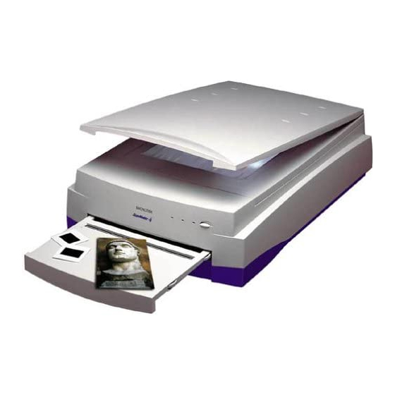
Page 24: Components
Components 1. ScanMaker 4 Scanner 8. Universal Glass Film Holder 2. SCSI cable 9. Main Holder 3. Power Cable 10. 35mm Batch Slide Holder 4. Adaptec SCSI 2902E Interface Card 11. 35mm Filmstrip Holder (for PC model only) 12. 4" x 5" Batch Film Holder 5. - Page 25 Scanner cover Glass surface Reflective material Horizontal ruler Power switch Power indicator (green LED) Ready indicator for reflective materials (orange LED) Ready indicator for transparent films (orange LED) Transparency tray ADF interface (Automatic Document Feeder) Power connector SCSI 50-pin connector SCSI 25-pin connector...
-
Page 26: Specifications
Specifications Media Reflective materials; color or Interface SCSI interface black-and-white originals. Dimensions Transmitted materials; (L x W x H) 566mm x 387mm x 158mm parencies, film slides, and negative film strips. Weight Net 26.5lb. (11.6kg) Image Sensor Trilinear color with cold Voltage AC 100V to 240V cathode lamp.
Need help?
Do you have a question about the ScanMaker 4 and is the answer not in the manual?
Questions and answers