
Related Manuals for H3C MSR 50-40


Summary of Contents for H3C MSR 50-40
-
Page 1: Installation Guide
H3C MSR 50 Routers Installation Guide Hangzhou H3C Technologies Co., Ltd. http://www.h3c.com Document version: T2-08047M-20101217-C-1.05... - Page 2 SecPro, SecPoint, SecEngine, SecPath, Comware, Secware, Storware, NQA, VVG, V G, V G, PSPT, XGbus, N-Bus, TiGem, InnoVision and HUASAN are trademarks of Hangzhou H3C Technologies Co., Ltd. All other trademarks that may be mentioned in this manual are the property of their respective owners Notice The information in this document is subject to change without notice.
- Page 3 Preface The H3C MSR 50 Routers Installation Guide describes how to install the H3C MSR 50 Routers, maintain software and hardware of the router, and solve problems you may encounter during the installation process. This preface includes: Audience • •...
- Page 4 Represents a routing-capable device, such as a router or Layer 3 switch. Represents a generic switch, such as a Layer 2 or Layer 3 switch, or a router that supports Layer 2 forwarding and other Layer 2 features. About the H3C MSR documentation set The H3C MSR documentation set includes: Category...
-
Page 5: Obtaining Documentation
Obtaining documentation You can access the most up-to-date H3C product documentation on the World Wide Web at http://www.h3c.com. Click the links on the top navigation bar to obtain different categories of product documentation: [Technical Support & Documents > Technical Documents] –... -
Page 6: Table Of Contents
Contents Overview ······································································································································································ 1 Introduction ········································································································································································1 Hardware Specifications ·········································································································································1 MSR 50-40/50-60 Routers ·····································································································································2 Generic Modules·······························································································································································4 MPUF/MPU-G2 ························································································································································4 MSCA/MSCB ························································································································································ 12 PSU ········································································································································································· 13 FAN Module ·························································································································································· 13 SIC/DSIC and FIC/DFIC Interface Cards··········································································································· 14 ESM Module ·························································································································································· 14 Voice Module ························································································································································ 15 Installation Preparations ············································································································································16... - Page 7 Powering on the Router········································································································································· 36 Startup Process······················································································································································· 37 Configuration Fundamentals ········································································································································· 38 Basic Configuration Procedures··························································································································· 38 Command Line Interface······································································································································· 38 Arranging Slots and Numbering Interfaces········································································································ 39 Software Maintenance···············································································································································41 Introduction ····································································································································································· 41 Files ········································································································································································· 41 Software Maintenance Methods·························································································································· 43 Maintaining Application Program and Configuration Through Command Lines···················································· 44 Maintaining the Router Through TFTP Server ·····································································································...
- Page 8 Installing/Removing Memory Bar ························································································································ 74 Replacing VPM ······························································································································································· 75 VPM Structure ························································································································································ 75 VPM Slot ································································································································································· 76 Installing/Removing VPM ····································································································································· 76 Installing/Removing ESM/VCPM Card ······················································································································· 76 Troubleshooting ··························································································································································78 Troubleshooting the Power System······························································································································· 78 Troubleshooting the Configuration System ·················································································································· 78 Troubleshooting Application Software Upgrade ········································································································ 79 Index ···········································································································································································81...
-
Page 9: Overview
(VPM) and voice co-processing module (VCPM). The MSR 50-40 routers are 3U in height and the MSR 50-60 are 4U in height. Slot 0 provided on the front panel of both the two models is for the main control board, which can be MPUF or MPU-G2 respectively. -
Page 10: Msr 50-40/50-60 Routers
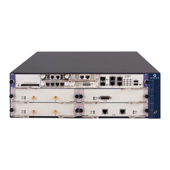
CF card. In this case, do not remove the CF card; otherwise hardware and software damage may occur. MSR 50-40/50-60 Routers Appearance Front view of an MSR 50-40 Figure 1 Front panel of an MSR 50-40 (10) (1) CF card LED (2) CF card (3) SIC slot 1... - Page 11 Rear view of an MSR 50-40 Figure 2 Rear view of an MSR 50-40 (1) MSC slot (2) System power 1 slot (3) System power 0 slot (4) System power socket (5) Grounding terminal (6) Fan slot Front view of an MSR 50-60...
-
Page 12: Generic Modules
Rear view of an MSR 50-60 Figure 4 Rear view of an MSR 50-60 (1) MSC slot (2) System power 2 slot (PoE) (3) System power 1 slot (4) System power 0 slot (5) System power socket (6) Grounding terminal (7) Fan slot NOTE: The figures above illustrate the components of a router with MPUF installed. - Page 13 Appearance Figure 5 MPUF front view Figure 6 MPUF internal structure Figure 7 MPU-G2 internal structure Specifications Table 2 Technical specifications for MPUF/MPU-G2 Item MPUF MPU-G2 3 GE Combo interfaces 2 GE Combo interfaces 1 AUX port 1 AUX port Interfaces 1 console port 1 console port...
- Page 14 Item MPUF MPU-G2 DDR SDRAM DDR II Memory Default: 512 MB Default: 1 GB Max: 1 GB Max: 2 GB Default: 256 MB Default: 256 MB CF Card Max: 1 GB Max: 1 GB Slot 4 SIC slots — NOTE: DDR SDRAM (synchronous dynamic random access memory) is the memory, which provides software •...
- Page 15 Figure 9 Big view of the LEDs and interfaces on an MPUF ( 9 ) (10) (11) (14) (19) (18) (24) (16) (13) (22) (12) (23) (15) (21) (20) (17) (25) (1) System LED (SYS) (2) Fan LED (FAN) (3) Power LED 1 (PWR1) (4) Power LED 0 (PWR0) (5) VPM LED 3 (VPM3) (6) VPM LED 2 (VPM2)
- Page 16 Figure 10 Big view of the LEDs and interfaces on an MPU-G2 (1) Fixed gigabit optical interface 2 (2) Fixed gigabit electrical interface 2 (3) Fixed gigabit optical interface 1 (4) Fixed gigabit electrical interface 1 (5) Fixed gigabit optical interface 0 (6) Fixed gigabit electrical interface 0 (7) Fixed 100 Mbps electrical interface 0 (8) USB interface...
- Page 17 Color Status Meaning The FAN module is not present. Green & Steady green The FAN module is working normally. yellow Yellow The FAN module has failed. VPMx is not present. Green & Steady green VPMx is present, yellow Yellow VPMx has failed. ESMx is not present.
- Page 18 Console port Table 4 Console port attributes Attribute Description Connector RJ-45 Interface standard RS232 9600 bps to 115200 bps Baud rate 9600 bps (default) Connecting to the ASCII terminal Connecting to the serial interface of the local PC and running terminal Function emulation program on the PC.
- Page 19 Table 7 1000 Mbps Ethernet optical interface attributes Description Single-mode Multi-mode Single-mode Single-mode Single-mode Attribute ultra-long short-haul (850 medium-haul long-haul long-haul haul (1550 (1310 nm) (1310 nm) (1550 nm) Connector SFP/LC 62.5/125 μm 9/125 μm 9/125 μm 9/125 μm 9/125 μm Optical fiber multi-mode single-mode...
-
Page 20: Msca/Mscb
MSCA/MSCB Appearance Figure 11 MSCA front view Figure 12 MSCB front view Specifications Table 8 MSCA/MSCB specifications Item MSCA MSCB ESM slot VCPM slot VPM slot NOTE: MSC (multi-service card) is installed in the slot provided on the backplane of the MSR 50 routers to carry •... -
Page 21: Psu
FAN Module Functions The MSR 50-40 is configured with six fans; the MSR 50-60 is configured with eight fans. These fans are working in pairs and the two fans in each pair are working in redundancy. When all these fans are working normally, the operating temperature of the system can be maintained between 0°C and 55°C... -
Page 22: Sic/Dsic And Fic/Dfic Interface Cards
temperature of the system can maintain. The routing speed of the fans is adjusted by the fan controller on the main control board and between 50% and 100% depending on the system temperature. When the system temperature rises above the high-temperature threshold set by the fan controller, the fans are rotating at full speed (100%);... -
Page 23: Voice Module
Table 11 Encryption card attributes Attribute Description Protocol IPsec Key algorithms: DES, 3DES, AES Hardware encryption algorithm Authentication algorithms: HMAC-MD5-96, HMAC-SHA-1-96 Voice Module VPM (Voice Processing Module) functions to implement the encryption/decryption, EC and CNG of voices. VCPM (Voice Co-Processing Module) processes the voice data together with VPM. Voice co-processing module (RT-VCPM) •... -
Page 24: Installation Preparations
Installation Preparations Requirements on Environment The MSR 50 routers are designed for indoor applications. To ensure the normal operation and prolong their service life, the following requirements for installation site must be met. Requirements on Temperature/Humidity To ensure the normal operation and prolong their service life, certain requirements on temperature and humidity in the equipment room shall be met. -
Page 25: Requirements On Electrostatic Discharge Prevention
Table 14 Limitation on harmful gases in equipment room Max. (mg/m 0.006 0.05 0.01 Requirements on Electrostatic Discharge Prevention Although many antistatic considerations have been given to MSR 50, damage to the router’s circuit or even the whole equipment may still happen when the static electricity exceeds the tolerance threshold. In the communication network to which the routers are connected, static induction mainly comes from two aspects: external electric fields such as outdoor high voltage power line or thunder and internal environment like flooring materials or the whole equipment structure. -
Page 26: Requirements On Workbench
Ensure the ground point of the socket of AC power supply is well grounded. • To enhance the lightning protection capability of the power supply, a lightning arrester could be • installed at the input end of the power supply. As for the signal line outdoors to which the interface modules of MSR 50 routers are connected, •... - Page 27 Cables PGND wire and power cord • Console cable • Optional cables • Meters and equipment Hub or LAN switch • Console terminal (it could be a PC) • Equipment related to the selected modules • Multimeter • CAUTION: None of the above-mentioned installation tools, meters, and equipment is shipped with MSR 50 routers.
-
Page 28: Installation
Installation Installation Process Figure 16 MSR 50 Routers installation process Installing the Cabinet If you install the router not in a cabinet or install it in a cabinet from other manufacturers, you can skip this process. Installing the Router Install the router after you have completed the installation preparations. The router can be installed: On a workbench •... -
Page 29: Installing The Router On A Workbench
Do not place heavy objects on the router. • Installing the Router in a Cabinet You can install an MSR 50 router in a 19-inch standard cabinet, such as an H3C N68 rack. For the installation of an N68 rack, refer to N68 Cabinet Installation Guide. Dimensions... -
Page 30: Installing Generic Modules
Figure 17 Installing MSR 50 Router in a rack (1) Mounting brackets (2) Guide rail Installing Generic Modules Installing generic modules includes installing the main control board, PSUs, the FAN module, and FICs. For more information about the main control board, PSUs, FAN module and their installation, refer to Chapter 6 “Hardware Maintenance”... -
Page 31: Connecting The Power Cord
Connecting the Power Cord Based on power supply mode, the MSR 50-40 and MSR 50-60 each have two models: DC, AC. You can choose suitable models as needed. -
Page 32: Connecting The Dc Power Cord
Figure 19 Power socket on AC-powered units (1) Power switch (2) AC input AC power socket (recommended) You are recommended to use a three-terminal single-phase power socket with ground contact, which must be grounded reliably. Normally, the ground contact of the power supply system in a building was buried during construction and cabling. -
Page 33: Connecting The Console Terminal
Connecting the DC power cord Figure 21 Sketch map of DC power cord Table 17 Connection of the DC power cord between the DC power supply and the router –48 VDC power supply Router X2 (–48 VDC connector, blue) X1.A1 X3 (BGND connector, black) X1.A3 Make sure that the PGND is properly grounded to the earth. -
Page 34: Fixed Interfaces
Console cable Console cable is an eight-wire shielded cable. At one end of the cable is a crimped RJ-45 connector to the console port on the router; at the other end of the cable is a DB-9 (female) connector to the serial port on the console terminal. - Page 35 1000 Mbps Ethernet interface MSR 50 Routers are available with fixed 1000 Mbps Ethernet COMBO interface, and Ethernet modules/cards for expansion. For more information, refer to the appendix in MSR Series Routers Interface Module Manual. The following table describes Ethernet interface attributes. Table 20 1000 Mbps Electrical Ethernet interface attributes Attribute Description...
- Page 36 NOTE: The fiber-optic and electrical connections that a 10/100/1000 Mbps Ethernet interface provides cannot • be used at the same time. If both connections are present, you can configure which connection takes effect through commands. By default, the electrical connection works. MDI (media dependent interface) is a typical type of Ethernet interface provided by network adapters.
-
Page 37: Connecting Aux To A Modem
Connecting electrical Ethernet interface cable Follow the steps below to connect an Ethernet cable: Connect one end of the Ethernet cable to an Ethernet port on the router and the other end to another Step1 device. For a 10/100/1000 Mbps port, connect it to a PC or another router using a crossover cable or to •... -
Page 38: Interface Card Module
Figure 24 AUX cable Connecting the AUX cable Follow these steps to connect the AUX cable. Plug the RJ-45 connector of the cable into the AUX port on the main control board. Step1 Plug the DB-25 or DB-9 connector into the serial port on the analog modem. Step2 When using the AUX interface for remote configuration or dial backup, you need to connect the local modem to the remote modem through PSTN and then to the remote device. -
Page 39: Installing Slide Rail
FIC slide rail Figure 26 FIC slide rail Installing Slide Rail Figure 27 Install an FIC slide rail Figure 28 Installation finished... -
Page 40: Removing Slide Rail
CAUTION: The design of demountable slide rail greatly facilitates users to extend their services. The slide rail is fixed • on chassis through special structure. When you need to install a DFIC, you only need to uninstall the rail and install the module. The rail may deviate out of external force when you install a DFIC, thus the DFIC on the other side cannot be installed normally. -
Page 41: Verifying Installation
Verifying Installation During router installation, you must verify installation each time you power on the router, making sure that: There is enough space around the router for heat-dissipation, and the workbench is stable enough. • The power supply that the power cord connects to is compliant with that required by the router. •... -
Page 42: Startup And Configuration
Startup and Configuration Startup You can only configure the router through the console port if it is the first time you use it. Setting up Configuration Environment Connecting the router to a console terminal To set up the local configuration environment, RJ-45 connector of the console cable needs to be connected to the console port on the router, and DB-9 connector to the serial interface of a PC, as shown in the following figure. - Page 43 Figure 32 Local configuration connection interface Set serial interface parameters. As shown in Figure 33, in the properties dialog box of the serial interface, Step2 set the baud rate to 9600, data bit to 8, no parity check, stop bit to 1, and flow control to none. Then, click OK to return to the HyperTerminal window.
-
Page 44: Powering On The Router
Figure 34 Set terminal type Powering on the Router Checking before power-on Check according to the following items before powering on the router. Whether the power cord and PGND wire are correctly connected. • Whether the voltage of the power supply complies with the requirement of the router. •... -
Page 45: Startup Process
After power-on or during the reboot process, the following information is displayed on the terminal: System application is starting... Booting Normal Extend BootWare..************************************************************************** H3C MSR50-40 BootWare, Version 1.08 ************************************************************************** Copyright (c) 2004-2008 Hangzhou H3C Technologies Co., Ltd. Compiled Date : Apr 16 2008 CPU Type : MPC7448 CPU L1 Cache : 32KB... -
Page 46: Configuration Fundamentals
Press Enter. The router enters user view and you can configure the router. Configuration Fundamentals In general, the configuration steps are as follows: Before configuring the router, the networking requirements should be made specific, which include Step1 networking purpose, the role of the router in the network, the division of subnets, WAN type and transmission medium, the network security policy and reliability. -
Page 47: Arranging Slots And Numbering Interfaces
The MSR 50 provides many types of interfaces, such as Console, AUX, Ethernet, serial (synchronous/asynchronous), and asynchronous port. The following describes how these interfaces are numbered. Figure 35 Slot arrangement on the MSR 50-40 (1) Slot 0 (2) Slot 1... - Page 48 • left to right. If you install an FIC- 1 FE and an FIC-2FE respectively in SLOT5 and SLOT6 on the MSR 50-40, the Ethernet interfaces are numbered as follows: The Ethernet interface on the FIC- 1 FE is Ethernet 5/0;...
-
Page 49: Software Maintenance
Software Maintenance Introduction Files BootWare program file The file is used to boot an application. A complete BootWare file includes two segments: basic and extended. The basic section is used for the basic initialization of the system. • The extended section provides abundant human-computer interaction (HCI) functions and is used to •... - Page 50 NOTE: The application programs for system boot can be type M, B and S, but not type N. You can store them • in Flash memory, but only one for each. For example, if an M+B file exists, it is impossible to have another M or B file.
-
Page 51: Software Maintenance Methods
CAUTION: The file name cannot be longer than 64 characters (including drive letter and a string terminator. If the • drive letter is “CFA0: /”, the file name can be at most [ 64-1-6 ] = 57 characters in length; or, errors will occur in file operation. -
Page 52: Maintaining Application Program And Configuration Through Command Lines
Figure 37 Upgrade flowchart for BootWare and Comware under Comware V5 environment Start Comware version Upgrade Comware ? Choose correct Comware Choose upgrade mode Via network interface Xmodem upgrade TFTP upgrade upgrade Upgrade Maintaining Application Program and Configuration Through Command Lines After the router is booted, you can upgrade and back up an application program, and back up and restore configurations through command lines. - Page 53 Figure 38 Network diagram for maintenance through command lines Configure the IP addresses of both sides on the same network. For example, the IP address of the TFTP server is set to 192.168.1.1, and that of the Ethernet interface connected to it (GigabitEthernet 0/0 in this example) is set to 192.168.1.2.
- Page 54 TFTP: 1045 bytes received in 0 second(s) File downloaded successfully. If a startup.cfg file already exists in the router, the system prompts you whether to overwrite it. You can type Y or y to overwrite it. Upgrading the application programs After setting up the environment, perform the following operations on the device (the application name is msr.bin for example): Use the save command to save the current configuration:...
-
Page 55: Maintaining The Router Through Ftp Server
Before using FTP, you need to install the FTP client. No FTP client is shipped with the H3C MSR 20- 1 X routers. In the following example, the FTP client application program is the built-in Windows XP FTP client. - Page 56 Figure 39 Maintain the router serving as the server Ethernet cable Router TFTP/FTP Server Console cable TFTP/FTP Client Configure the IP addresses of both sides on the same network. In this section, the IP address of the FTP client (PC) is set to 192.168.1.1, and that of the connected Ethernet interface on the router (GigabitEthernet 0/0) is set to 192.168.1.2.
- Page 57 After you correctly enter the username and password, the system prompts login success. You can then maintain the router, for example, modify transmission mode and local path, and back up files. In this example, the main.bin file on the router is copied to the PC. ftp>...
-
Page 58: Bootware Menu
Configure the IP addresses of both sides on the same network. In this section, the IP address of the FTP server is set to 192.168.1.1, and that of the connected Ethernet interface on the router (GigabitEthernet 0/0 in this example) is set to 192.168.1.2. Use the ping command to check the connectivity. Maintain the router through the terminal connected with the console interface of the router. - Page 59 ************************************************************************** Copyright (c) 2004-2008 Hangzhou H3C Technologies Co., Ltd. Compiled Date : Apr 16 2008 CPU Type : MPC7448 CPU L1 Cache : 32KB CPU L2 Cache : 1024KB CPU Clock Speed : 1700MHz Memory Type : DDR2 SDRAM Memory Size...
-
Page 60: Bootware Submenus
Enter your choice(0-9): This menu is described as follows: Table 23 Main BootWare menu Item Description <1> Boot System Bootstrap. Enter the serial interface submenu. For details about <2> Enter Serial SubMenu the submenu, refer to Serial interface submenu page 52. Enter the Ethernet interface submenu. - Page 61 Enter your choice(0-5): The submenu is described as follows: Table 24 BootWare serial interface submenu Item Description <1> Download Application Program To SDRAM And Download an application program to SDRAM and run <2> Update Main Application File Upgrade the main application program. <3>...
- Page 62 |<1> Display All File(s) |<2> Set Application File type |<3> Set Configuration File type |<4> Delete File |<0> Exit To Main Menu ========================================================================== Enter your choice(0-4): The submenu is described as follows: Table 26 File control submenu Item Description <1> Display All File Display all files.
-
Page 63: Upgrading An Application Program Through An Ethernet Interface
Upgrading an Application Program Through an Ethernet Interface Enter 3 in the BootWare menu to enter the Ethernet interface submenu. For details about the submenu, refer to BootWare Submenus on page 52. Configuring Ethernet Interface Parameters Before upgrading an application program through an Ethernet interface, we need to configure the Ethernet interface on the router as follows: Enter 3 in the BootWare menu to enter the Ethernet interface submenu. -
Page 64: Upgrading Procedure
Parameter Description FTP User Name This option is not available for TFTP. FTP User Password This option is not available for TFTP. NOTE: Upon upgrade failure, the system prompts “Loading failed”. In this case, please reboot the router to • validate the reset IP address. - Page 65 Modify Ethernet interface parameters. For details, refer to Configuring Ethernet Interface Parameters Step2 page 55. Enter 3 in the main BootWare menu to enter the Ethernet Interface submenu. For example, when Step3 upgrading the main application program, enter 2: Loading.............................
-
Page 66: Upgrading Bootware Through Ethernet Interface
CAUTION: If the input file name is the same as the original one in the Flash memory, the system prompts that “The • file is exist, will you overwrite it? [Y/N]”. Enter Y to overwrite the original file. The new application program file will then overwrite the original file of this type, ensuring the uniqueness of the application program on the device. -
Page 67: Modifying Serial Interface Parameters
If the check is passed, the receiver sends an acknowledgement message to the sender. Upon • receiving the message, the sender continues to send the next packet. If the check fails, the receiver sends a negative acknowledgement message to the sender. Upon •... -
Page 68: Upgrading Bootware
Figure 43 Modify baud rate Select Call > Call to establish a new connection. Figure 44 Establish a new connection Press Enter to view the current baud rate and return to the previous menu. The system displays: The current baudrate is 115200 bps NOTE: Restore the baud rate in the HyperTerminal to 9600 bps after upgrading the BootWare. - Page 69 Enter 3 in the BootWare operation menu. The system displays: ===================<BOOTWARE OPERATION SERIAL SUB-MENU>=================== |<1> Update Full BootWare |<2> Update Extend BootWare |<3> Update Basic BootWare |<4> Modify Serial Interface Parameter |<0> Exit To Main Menu ========================================================================== Enter your choice(0-4): Enter 1, and the system displays: Please Start To Transfer File, Press <Ctrl+C>...
-
Page 70: Upgrading An Application Program Through A Serial Interface
NOTE: The file name, size and path vary in different situations. Before upgrading, check the current version of • BootWare and application program. Restore the baud rate in the HyperTerminal to 9600 bps after upgrading the BootWare. This ensures that •... - Page 71 Displaying all files Enter 1, and the system displays: Display all file(s) in cfa0 'M' = MAIN 'B' = BACKUP 'S' = SECURE 'N/A' = NOT ASSIGNED ========================================================================== |NO. Size(B) Time Type Name 640199 Dec/20/2007 09:53:16 N/A cfa0:/logfile/logfile.log 22165484 Dec/20/2007 09:18:10 B+S cfa0:/update.bin 1181 Dec/20/2007 09:42:54 N/A...
-
Page 72: Dealing With Password Loss
========================================================================== |<1> +Main |<2> -Main |<3> +Backup |<4> -Backup |<0> Exit ========================================================================== Enter your choice(0-4): You can set the file type to M (main) or B (backup) or cancel the setting by entering digits 1 to 4. Refer Introduction on page for details. -
Page 73: Bootware Password Loss
The system prompts the setting succeeds. When the main BootWare menu appears again, enter 0 to reboot the system. Step2 Set a new password in system view. Step3 [SYSTEM]user-interface console 0 [SYSTEM-ui-console0]authentication-mode password [SYSTEM-ui-console0]set authentication password simple 123456 The above information indicates that the password authentication is adopted on the console interface and the password is set to 123456 and stored in plain text. -
Page 74: Backing Up And Restoring Bootware
After you clear the super password, quit the menu and reboot the router, you can directly enter system view. The setting is valid for the first reboot of the router only. The super password will be restored after a second reboot. Backing Up and Restoring BootWare Enter 7 under the main BootWare menu to enter the BootWare operation submenu. -
Page 75: Hardware Maintenance
The tools are not available with the MSR 50. You must prepare one yourself. Internal Structure In the following section, the MSR 50-40 installed with the MPUF and MSCA is taken as an example. Figure 47 Internal structure (1) Power and SIC slot... -
Page 76: Removing/Installing Psus
Figure 48 MPUF internal structure (1) Memory bar slot (2) SIC slot (3) CF card slot Figure 49 MSCA internal structure (1) VPM slot (2) VCPM slot (3) ESM slot 1 (4) ESM slot 0 Removing/Installing PSUs Removing a PSU Follow these steps to remove a PSU: Remove the power cord connected to the PSU and loosen the two captive screws fastening the module Step1... -
Page 77: Installing A Psu
CAUTION: If you do not plan to replace the PSU soon, install a blank filler panel to ensure adequate ventilation and prevent dust. Installing a PSU Follow these steps to install a PSU: Hold the handle of the PSU, gently push it into the chassis along the guides until it well touches the power Step1 backplane inside the power slot. -
Page 78: Installing The Fan Module
Installing the Fan Module Hold the handle on the fan module with one hand and the bottom with the other hand. Slowly insert the Step1 fan module into the chassis along the guides until it well touches the backplane. Fasten the captive screws on the fan module. Step2 Power on the router and check that the FAN LED is solid ON. -
Page 79: Installing The Mpuf
Turn off the power switch (or switches if two PSUs are installed). Step1 Loosen the captive screws at both sides of the MPUF. Step2 Pull the handles at both side of the MPUF outward and gently pull the card out along the guides until it Step3 is completely separated from the chassis. -
Page 80: Installing/Removing Cf Card
Align the edges of the MSCA with the guides in the MSCA slot and push the card into the router. Push Step2 the ejector levers at both side of the MSCA inward until they form the smallest degree with the MPUF panel. -
Page 81: Replacing Memory Bar
Push the spring button hard in the orientation shown in the figure below, and the CF card on the right Step3 pops up a little. Take it out. Figure 56 Press the spring button to make the card spring out CAUTION: Do not insert or remove the card when the router is booting or the LED is blinking to avoid hardware damage. -
Page 82: Memory Bar Structure
CAUTION: Hold the memory bar by its edge and avoid touching the components on its surface. An improper • operation might result in damage. It is normal that you feel hard when removing the memory bar, but do not overexert. •... -
Page 83: Replacing Vpm
Figure 60 Install memory bar into the slot Follow the steps below to remove the memory bar: Make sure all power interfaces are shut down, and then proceed. Step1 Press the spring clips on the two sides of the memory bar, and pull outwards levelly until the memory bar Step2 separates with the spring clips and forms an angle of 45 degrees with the main board. -
Page 84: Vpm Slot
VPM Slot Figure 63 VPM slot Installing/Removing VPM Follow the steps below to install the VPM: Make sure all power interfaces are shut down, and then proceed. Step1 Align the VPM golden finger with the slot on the main board. Step2 Insert the VPM vertically into the slot. - Page 85 Align the card interface with the slot and press down vertically to install the card on the board. Then, Step4 align the screw eye with the card bracket. Fasten the card on the bracket with dedicated screws, making sure the card is level and firm. Step5 Install the interface board and power it on.
-
Page 86: Troubleshooting
Troubleshooting Troubleshooting the Power System Symptom: The PWR LED RUN is OFF or blinking. Solution: Check that: The power switch on the router is turned on. • The switch of the power source is turned on. • The power cord is correctly connected. •... -
Page 87: Troubleshooting Application Software Upgrade
Troubleshooting Application Software Upgrade Symptom 1: When upgrading the Comware software using TFTP/FTP, the system displays: =========================<ETHERNET PARAMETER SET>========================= |Note: '.' = Clear field. '-' = Go to previous field. Ctrl+D = Quit. ========================================================================== Protocol (FTP or TFTP) :tftp ftp Load File Name :host Target File Name... - Page 88 11487495 bytes downloaded. Something wrong with the file. Solution: Fault occurs because an incorrect application file is downloaded. Download the correct application program file. NOTE: The bar code labels on the chassis and the FICs contain information about production and servicing. •...
-
Page 89: Index
Index Removing/Installing the Fan Module Removing/Installing the MPUF Backing Up and Restoring BootWare Replacing Memory Bar BootWare Menu Replacing VPM Requirements on Environment Configuration Fundamentals Connecting the Console Terminal Safety Precautions Connecting the PGND Startup Connecting the Power Cord Troubleshooting Application Software Upgrade Dealing with Password Loss Troubleshooting the Configuration System Troubleshooting the Power System...
Need help?
Do you have a question about the MSR 50-40 and is the answer not in the manual?
Questions and answers