Table of Contents
Advertisement
Quick Links
Digital Wireless
Transmitter
The supplied CD-ROM includes the Operating Instructions for the DWT-P01
Digital Wireless Transmitter (English, French, German, Italian, and Spanish
versions) and the frequency lists (English version) in PDF format.
For more details, see "Using the CD-ROM manual" on page 8.
Operating Instructions
Before operating the unit, please read this manual thoroughly
and retain it for future reference.
DWT-P01
© 2010 Sony Corporation
4-261-563-06 (1)
F
Advertisement
Table of Contents

Related Manuals for Sony DWT-P01


Summary of Contents for Sony DWT-P01
-
Page 1: Operating Instructions
4-261-563-06 (1) Digital Wireless Transmitter The supplied CD-ROM includes the Operating Instructions for the DWT-P01 Digital Wireless Transmitter (English, French, German, Italian, and Spanish versions) and the frequency lists (English version) in PDF format. For more details, see “Using the CD-ROM manual” on page 8. - Page 2 - Increase the separation between the For the customers in the U.S.A. equipment and receiver. - Connect the equipment into an outlet on Use of Sony wireless devices is regulated a circuit different from that to which the by the Federal Communications receiver is connected.
- Page 3 Inc. remplies. Address: 16530 Via Esprillo, San Diego, CA 92127 U.S.A. L’usage des appareils sans fil Sony est Telephone Number: 858-942-2230 réglementé par l’Industrie Canada comme décrit dans leur Cahier des Normes This device complies with part 15 of the Radioélectriques CNR-123.
- Page 4 MODULE INTÉGRÉ RM-215 Pour les clients en Europe Avant d’utiliser l’appareil, prière de lire le ID FCC : AK8RM215 document de précautions R&TTE fourni IC : 409B-RM215 séparément. For the customers in the U.S.A. Für Kunden in Europa You are cautioned that any changes or Bevor Sie dieses Gerät benutzen, lesen Sie modifications not expressly approved in bitte das separate die R&TTE-Richtlinien...
- Page 5 Για τους πελάτες που διαμένουν ostrożności wynikających z dyrektywy w sprawie urządzeń radiowych i σε χώρες της Ευρώπης końcowych urządzeń Πριν χρησιμοποιήσετε αυτήν τη telekomunikacyjnych oraz wzajemnego μονάδα, διαβάστε το ξεχωριστ uznawania ich zgodności (dyrektywa έγγραφο λήψης προφυλάξεων της R&TTE). οδηγίας...
-
Page 6: Table Of Contents
Table of Contents Features .......... 7 Displaying the accumulated Using the CD-ROM manual ..8 use time (TIME) .....22 Parts Identification ......9 +48 V power supply setting Power Supply ....... 11 (+48V) ........23 Installing the batteries ... 11 Setting the encrypted Setting the Transmission transmission function Channel ........ -
Page 7: Features
Wireless Studio control software installed on a computer The DWT-P01 is a digital wireless connected to the receiver. transmitter for a UHF synthesized wireless For example, the settings of a transmitter... -
Page 8: Using The Cd-Rom Manual
For details, see “+48 V power supply setting want to read. (+48V)” on page 23. Note If you have lost or damaged the CD-ROM, you can purchase a new one from your Sony dealer or Sony service counter. Using the CD-ROM manual... -
Page 9: Parts Identification
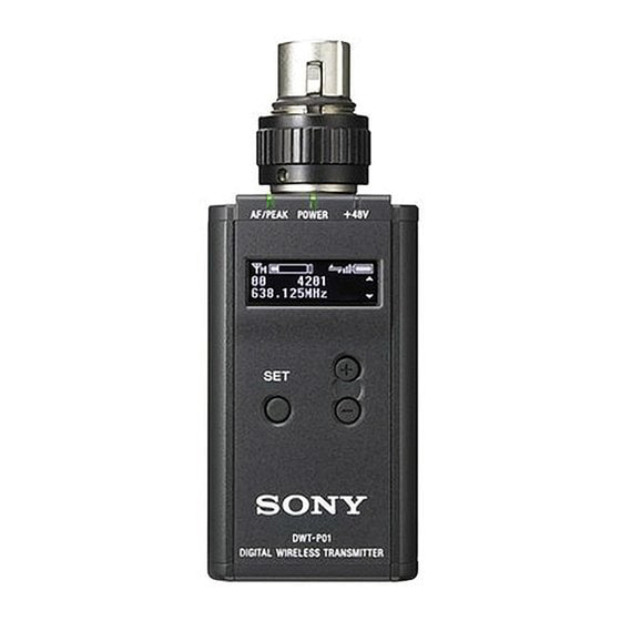
Parts Identification To connect a microphone or a cable Microphone or a cable (optional) Front Turn the connector ring clockwise (1) and insert the microphone or cable connector into the audio input connector until it is fully engaged (2). Then turn the connector ring counterclockwise to Bottom secure the latch (3). - Page 10 e Display section G Cross Remote condition indication Indicates the signal transmission condition of the wireless remote control function (4 levels). : Good transmission : Somewhat good transmission : Somewhat poor transmission : Poor transmission : Unable to communicate with paired receiver A RF (radio frequency) transmission When the wireless remote control function...
-
Page 11: Power Supply
i POWER switch Power Supply Turns the transmitter ON or OFF. j Battery compartment Accommodates two LR6 (size AA) alkaline batteries. The transmitter can operate on two LR6 (size AA) alkaline batteries continuously For details on how to insert the batteries, see for about 5.0 hours at 25 °C (77 °F). -
Page 12: Setting The Transmission Channel
TYPE1, the power status is indicated Transmission based on the use of new LR6 (size AA) Channel Sony Alkaline batteries. An incorrect indication may result when a different kind of batteries, a different brand of batteries or old batteries are used. If you... -
Page 13: Selecting The Group/ Channel
Set the transmitter group (GP) and channel (CH) as follows: For details, see“Pairing with a receiver” on page 14. For details on groups and channels, refer to “Sony Digital Wireless Microphone System Frequency Lists” on the supplied CD-ROM. For details on menu operation, see “Basic Menu Operations”... -
Page 14: Using The Cross Remote
To carry out pairing through menu Using the Cross operations on the transmitter, do the following. Remote Set the receiver to be used for controlling the transmitter to pairing mode. This transmitter is equipped with a wireless For details, refer to the operating instructions remote control function that can be used to supplied with the receiver. - Page 15 you must perform the pairing procedure • When it becomes hard to use the remote for that receiver. control, the remote control may be • Multiple transmitters cannot be paired improved by switching the wireless with the same receiver. remote control function off, then on again •...
-
Page 16: Using The Encrypted Transmission Function
The encryption key used by the transmitter Using the and receiver is newly generated for each key transmission, resulting in highly secure Encrypted communication. The encryption key used between the Transmission transmitter and the receiver is saved when the power is turned off, so the encrypted Function transmission can be resumed the next time the power is turned on. -
Page 17: Using Password Mode (Password)
Press the + or – button repeatedly to USB cable (supplied) select PASSWORD, and then press the SET button. Input a password of up to eight characters on the transmitter. To enter a password, use the procedure described in “Naming of transmitter (NAME)” on page 20. -
Page 18: Using A Usb Keyboard
Characters that can be entered from Using a USB a USB keyboard: (space), 0, 1, 2, 3, 4, 5, 6, 7, 8, 9, A, B, C, D, E, F, G, H, I, J, K, L, Keyboard M, N, O, P, Q, R, S, T, U, V, W, X, Y, Z, !, #, &, $, @, +, -, =, _, (, ), [, ] (Passwords may consist of the numbers 0 to 9 and letters A to Z only.) -
Page 19: Basic Menu Operations
• RF REMOTE (wireless remote control) Basic Menu function • BRIGHTNESS (display brightness) Operations setting • DIMMER MODE (automatic dimming of the display) setting • FACTORY PRESET (factory setting) function Function name • VERSION (software version) indication Item to be set Press the + or –... -
Page 20: Setting Menus
(BAND) Naming of transmitter Match the frequency range on this (NAME) transmitter to that of the Sony digital wireless receiver. You can specify a transmitter name of up to See “Carrier Frequencies and Channel 16 characters. The factory setting for the Steps”... -
Page 21: Selecting The Group/Channel (Gp/Ch)
power on. And then, change the setting Selecting the group/ after the signal transmission has stopped. channel (GP/CH) • To start signal transmission with the selected RF output power setting, turn off See “Carrier Frequencies and Channel the power and then turn it on again. Steps”... -
Page 22: Low-Cut Filter Setting (Lcf)
TYPE1: The power status is indicated Low-cut filter is set according to the based on characteristics of new LR6 (size selected frequency. AA) Sony Alkaline batteries. Select this for LR6 (size AA) alkaline batteries. Using wireless remote control, this function TYPE2: Select this for rechargeable can be controlled from the receiver and nickel-metal-hydride batteries. -
Page 23: Power Supply Setting (+48V)
For details on wireless remote control function, see Generating an internal “Using the Cross Remote” on page 14. signal (INTERNAL SG) +48 V power supply setting This transmitter generates a 1-kHz reference level sine wave that can be used to (+48V) adjust or check the audio level of the You can turn the +48 V power supply on or... -
Page 24: Cross Remote (Rf Remote)
AUTO OFF: The display turns off after 30 For details on wireless remote control function, see “Using the Cross Remote” on page 14. seconds. The display goes on again when you press the SET, +, or – button. AUTO DIMMER: The display dims after Cross Remote (RF REMOTE) 30 seconds. -
Page 25: Block Diagram
Block Diagram Digital signal processor Attenuator Head amp. Low-cut filter High- Audio A/D converter frequency codec circuit modulator Internal SG Block Diagram... -
Page 26: Troubleshooting
If you encounter a problem using this transmitter, use the following checklist to find a solution. For any problems with the receiver or adapter, refer to the operating instructions supplied with the respective device. If the problem persists, consult your Sony dealer. Symptom... - Page 27 Symptom Meanings Remedy There is too The microphone connected to Use the low-cut filter to cut the much bass. the transmitter produces bass. excessive bass because the frequency response of the transmitter extends into the low 20-Hz range. The power The POWER switch is locked.
-
Page 28: Important Notes On Operation
Position the wireless and analog wireless devices. transmitter so that interference is For details, refer to “Sony Digital Wireless minimized. Microphone System Frequency Lists” on the • To avoid degradation of the signal-to- supplied CD-ROM. -
Page 29: Specifications
Note on microphone and Specifications transmitter combinations It is recommended that you use the Sony ECM-673/9X, ECM-674/9X, or ECM-678/ 9X Electret Condenser Microphone with Transmitting section this transmitter. The transmission signal Oscillator type may cause noise on some microphones. If... - Page 30 Operating temperature Always verify that the unit is operating 0 °C to 50 °C (32 °F to 122 °F) properly before use. SONY WILL NOT Storage temperature BE LIABLE FOR DAMAGES OF ANY –20 °C to +60 °C (–4 °F to +140 °F)
-
Page 31: Carrier Frequencies And Channel Steps
Carrier Frequencies and Channel Steps Underlined items are the factory setting. US models Channel step: 25 kHz Group/channel Model No. Frequency band Frequency (factory setting) TV14-17 470.125 - 493.875 MHz U1424 TV18-21 494.125 - 517.875 MHz 00 1801 494.125 MHz TV22-25 518.125 - 541.875 MHz TV30-33... - Page 32 European models Channel step: 25 kHz Group/channel Model No. Frequency band Frequency (factory setting) TV33-35 566.025 - 590.000 MHz CE3338 TV36-37 590.025 - 606.000 MHz 00 3301 566.125 MHz TV38-40 606.025 - 630.000 MHz TV42-44 638.025 - 662.000 MHz CE4248 TV45-47 662.025 - 686.000 MHz 00 4201 638.125 MHz...
- Page 33 Carrier Frequencies and Channel Steps...
- Page 34 Carrier Frequencies and Channel Steps...
- Page 35 Carrier Frequencies and Channel Steps...
- Page 36 Sony Corporation Printed in Japan...
Need help?
Do you have a question about the DWT-P01 and is the answer not in the manual?
Questions and answers