Sony DWT-B01 Operating Instructions Manual
Digital wireless transmitter
Hide thumbs
Also See for DWT-B01:
- Brochure & specs (12 pages) ,
- Quick manual (12 pages) ,
- Operating instructions manual (44 pages)
Table of Contents
Advertisement
Quick Links
Digital Wireless
Transmitter
The supplied CD-ROM includes the Operating Instructions for the DWT-B01
digital wireless transmitter (English, French, German, Italian, and Spanish
versions). For more details, see "Using the CD-ROM manual" on page 11.
Operating Instructions
DWT-B01
©2008 Sony Corporation
3-873-945-11 (1)
Advertisement
Table of Contents

Related Manuals for Sony DWT-B01


Summary of Contents for Sony DWT-B01
- Page 1 3-873-945-11 (1) Digital Wireless Transmitter The supplied CD-ROM includes the Operating Instructions for the DWT-B01 digital wireless transmitter (English, French, German, Italian, and Spanish versions). For more details, see “Using the CD-ROM manual” on page 11. Operating Instructions DWT-B01 ©2008 Sony Corporation...
- Page 2 Notice for customers in the prohibited per regulations of Industry Canada. U.S.A. The required antenna impedance is 50 Use of Sony wireless devices is regulated ohms. by the Federal Communications Commision as described in Part 74 subpart Notice for customers in Canada:...
- Page 3 For the customers in Europe utilisateurs au Canada: Hereby, Sony Corporation, declares that L’usage des appareils sans fil Sony est this DWT-B01 is in compliance with the réglementé par l’Industrie Canada comme essential requirements and other relevant décrit dans leur Cahier des Normes provisions of the Directive 1999/5/EC.
-
Page 4: Using The Cd-Rom Manual
Reader. In such a case, install the latest version you can download from the URL The supplied CD-ROM includes Operating mentioned in “Preparations” above. Instructions for the DWT-B01 (English, Note French, German, Italian, and Spanish versions) and the frequency lists (English If you have lost or damaged the CD-ROM, and Japanese versions). -
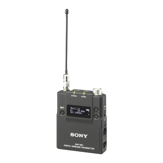
Page 5: Parts Identification
Parts identification To connect a microphone Microphone (optional) To secure the microphone cable connection, be sure to turn and lock the connector cover. + or – button Selects functions or values shown on the display. Holding down the – button while switching on the transmitter activates the pairing a Antenna operation for the wireless remote control... - Page 6 F Power switch lock indicator using key operations. By connecting the digital wireless receiver to this connector Indicates that the power switch is locked, with the supplied USB cable, you can preventing the transmitter from being exchange the encryption key for encrypted accidentally turned off or on.
-
Page 7: Power Supply
Note The indication is based on the use of new LR6 (size AA) Sony Alkaline batteries. An The transmitter can operate on two LR6 incorrect indication may result when a (size AA) alkaline batteries continuously different kind of batteries, a different brand for about 3.5 hours at 25°C (77°F). -
Page 8: Important Notes On Operation
The use of portable telephones and temperature range of 0°C to 50°C (32°F other communication devices near to 122°F). the DWT-B01 may result in malfunction and interference with • Operating the transmitter near electrical audio signals. It is recommended that... -
Page 9: Specifications
MIC: –22 dBu (with 0 dB Specifications attenuator) LINE: +24 dBu Audio attenuator adjustment range (pad) 0 to 48 dB (3dB steps, MIC input Transmitting section mode only) Oscillator type Crystal-controlled PLL synthesizer Carrier frequencies US models: U3040: 566 to 607 MHz (TV-30 to TV-36 channels);... - Page 10 Microphone input connector Dimensions Sony 4-pin (SMC9-4S) (female) (1) Input impedance 4.7 kohms or more, 0 dBu = 0.775 Frequency response 20 Hz to 22 kHz T.H.D 0.03% or less Type of emission G1E or G1D Dynamic range 106 dB or more...
- Page 11 Design and specifications are subject to change without notice. Note Always verify that the unit is operating properly before use. SONY WILL NOT BE LIABLE FOR DAMAGES OF ANY KIND INCLUDING, BUT NOT LIMITED TO, COMPENSATION OR REIMBURSEMENT ON ACCOUNT...
- Page 12 This model has an RF module of the FCC/IC approval built-in. BUILT IN MODULE RM-215 FCC ID: AK8RM215 IC: 409B-RM215...
Need help?
Do you have a question about the DWT-B01 and is the answer not in the manual?
Questions and answers