Sign In
Upload
Manuals
Brands
Viessmann Manuals
Boiler
Vitodens 200-W B2KE
Viessmann Vitodens 200-W B2KE Manuals
Manuals and User Guides for Viessmann Vitodens 200-W B2KE. We have
2
Viessmann Vitodens 200-W B2KE manuals available for free PDF download: Technical Manual, Installation And Service Instructions Manual
Viessmann Vitodens 200-W B2KE Technical Manual (156 pages)
Gas condensing boiler
Brand:
Viessmann
| Category:
Boiler
| Size: 30.31 MB
Table of Contents
Table of Contents
2
Product Description
4
Specification
6
Product Description
15
Specification
17
Product Description
22
Specification
25
Product Description
31
Specification
34
Product Description
39
Specification
42
Vitocell 100-W below the Boiler (Type CUGA and CUGA-A), Made from Steel, with Ceraprotect Enamel Coating
48
Delivered Condition
50
Vitocell 100-W, Type CVA, CVAA and CVAA-A Adjacent to the Boiler – 160, 200 and 300 L, White Finish, Made from Steel, with Ceraprotect Enamel Coating
51
Delivered Condition
54
Vitocell 200-W, Type EVIA-A and EVIA-A+Adjacent to the Boiler, 160 and 200 L White Finish, with Internal Indirect Coil, Made from Stainless Steel
55
Delivered Condition
56
Finish, Made from Steel with Ceraprotect Enamel Coating for Dual Mode DHW Heat Ing
58
Delivered Condition
61
Vitodens 200-W Installation Accessories
62
Valves/Fittings
63
Sub-Mounting Kit with Mixer
64
Mounting Frame
66
Further Accessories
67
Connections between the Vitodens and the DHW Cylinder
70
Installation Accessories for Vitodens 222-W
71
Valves/Fittings
72
Further Accessories
75
Flue Gas Cascade (Positive Pressure) for Multi Boiler Systems with Vitodens 200-W and 222-W
76
Installation Accessories for Vitodens 222-F
77
Installation Accessories for Vitodens 242-F
81
Divicon Heating Circuit Distributor and Low Loss Headers
86
Low Loss Headers
93
Siting, Installation
94
Siting the Vitodens 222-F and 242-F in Recesses
95
Electrical Connection
96
Minimum Clearances
97
Replacing Third Party Boilers with the Vitodens 200-W
105
Pre-Installation of the Vitodens 222-W
109
Installation of the Vitodens 222-F
115
Installation of the Vitodens 242-F
121
Decision Making Aids for DHW Heating
125
5 Vitodens 242-F
126
Separate DHW Cylinders
126
Connection on the DHW Side
127
DHW Cylinder Selection Tables
127
Condensate Connection
132
Condensate Drain Pipe and Neutralisation
133
Hydraulic Connection
134
General
134
Expansion Vessels
135
Low Loss Header
136
Intended Use
137
Control Unit
137
Control Unit with 7-Inch Screen - Modular Design
137
Control Unit with 3.5-Inch Screen - Modular Design
138
Functions
139
Information on Plusbus Subscribers
140
Frost Protection Function
140
Heating Curve Setting (Slope and Level)
140
Heating Systems with a Low Loss Header or Heating Water Buffer Cylinder
140
Flow Temperature Sensor
140
Cylinder Temperature Sensor
140
Specification - Control Unit
141
Accessories for Control Unit
141
Vitotrol 100, Type UTA
141
Vitotrol 100, Type UTDB
142
Vitotrol 100, Type UTDB-RF
142
Vitotrol 200-E
143
Outside Temperature Sensor
144
Room Temperature Sensor
144
Immersion Temperature Sensor
144
Cylinder Temperature Sensor
145
Contact Thermostat
145
Information on Plusbus Subscribers
145
EM-MX Mixer Extension Kit with Integral Mixer Motor
145
EM-M1 Mixer Extension Kit for Separate Mixer Motor
146
EM-MX Mixer Extension Kit for Divicon Heating Circuit Distribution
146
EM-P1 Extension
147
Solar Control Units
148
EM-EA1 Extension
150
Appendix 10.1 Regulations / Directives
151
Regulations and Directives
151
10. Appendix
152
Keyword Index
152
Advertisement
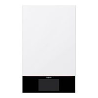
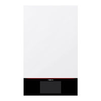
Viessmann Vitodens 200-W B2KE Installation And Service Instructions Manual (128 pages)
Wall mounted gas condensing boiler
Brand:
Viessmann
| Category:
Boiler
| Size: 24.74 MB
Table of Contents
Index Index
4
Table of Contents
4
Mounting the Boiler and Making Connections
11
Removing the Front Panel
11
Mounting the Boiler on the Pre-Plumbing Jig or Mounting Frame
11
Fitting the Boiler to the Wall Mounting Bracket
13
Fitting the Programming Unit Mounting Bracket on the Top of the Boiler
15
Connections on the Heating Water and DHW Sides
16
Condensate Connection
17
Filling the Trap with Water
17
Flue Gas Connection
17
Gas Connection
19
Electrical Connections
20
Opening the Wiring Chamber
20
Layout of the Electrical Connections
21
On-Site Connections on HMU Heat Management Unit
22
Outside Temperature Sensor
22
Connecting the Circulation Pump to P1 and P2
23
Connecting the Cylinder Temperature Sensor
23
Floating Switching Contact Connection
23
Checking the CAN Bus Terminator Switch Setting
24
Information on Connecting Plusbus Subscribers
24
Lh Abh (230 V ~)
24
Power Supply for Accessories at Plug
24
Power Supply Fö
26
Routing Connecting Cables/Leads
26
Wifi Operational Reliability and System Requirements
27
Angle of Penetration
28
Wireless Signal Range of Wifi Connection
28
Closing the Wiring Chamber
29
Fitting the Programming Unit and Front Panel
30
Programming Unit Located at the Bottom
30
Programming Unit Located at the Top
31
Steps - Commissioning, Inspection and Maintenance
32
Commissioning the System with the Commissioning Assistant
33
Filling the Heating System
36
Topping up the Heating Water
38
Checking All Connections on the Heating Water and DHW Sides for Leaks
38
Venting the Heating System
38
Checking the Gas Type
39
Converting the Gas Type for Operation with LPG and Natural Gas M
39
Removing the Front Panel
40
Moving the Programming Unit to the Service Position
41
Checking the Static Pressure and Supply Pressure
41
Function Sequence and Possible Faults
43
Adjusting the Pump Rate of the Integral Circulation Pump
44
Setting the Max. Heating Output
44
Activating Screed Drying
46
Removing the Burner
47
Tightness Test on Balanced Flue System (Annular Gap Check)
47
Checking the Burner Gasket and Burner Gauze Assembly
49
Checking and Adjusting the Ignition and Ionisation Electrodes
50
Checking the Back Draught Safety Device
50
Checking the Condensate Drain and Cleaning the Trap
51
Cleaning the Heating Surfaces
51
Checking the Neutralising System (if Installed)
53
Installing the Burner
53
Checking the Expansion Vessel and System Pressure
54
Checking the Flow Limiter (Only for Gas Condensing Combi Boiler)
54
Checking the Combustion Quality
55
Checking the Electrical Connections for Firm Seating 28. Checking All Gas Equipment for Tightness at Operating Pressure
55
Fitting the Front Panel
55
Checking the External LPG Safety Valve (if Installed)
57
Adjusting Heating Curves
57
Calling up and Resetting the Service Display
57
Instructing the System User
57
Matching the Control Unit to the Heating System
57
Checking the Flue System for Unrestricted Flow and Leaks
57
Calling up Parameters
59
General
59
Boiler
61
DHW (Domestic Hot Water)
63
Heating Circuit 1, Heating Circuit 2, Heating Circuit 3
65
Solar
70
Subscriber Numbers of Connected Extensions
72
Diagnosis
74
Checking Operating Data
74
Service Menu
74
Calling up the Service Menu
74
Exiting the Service Menu
74
Checking Outputs (Actuator Test)
75
Troubleshooting Fault Display on the Programming Unit
77
Fault Display on the Programming Unit
77
Fault Messages
79
Overview of Electronics Module
79
Repairs
97
Shutting down the Boiler
97
Removing the Boiler from the Pre-Plumbing Jig or Mounting Frame
98
Checking the Temperature Sensors
99
Information on Replacing the HMU Heat Management Unit and BCU Burner Control Unit
102
Replacing the HMI Connecting Cable
102
Replacing the Power Cable
102
Checking the Plate Heat Exchanger
103
Removing the Hydraulic Unit
104
Checking the Fuse
106
Function Description Appliance Functions
107
Filling Program
107
Heating Curve
107
Heating Mode
107
Venting Program
107
Screed Drying
109
Raising the Reduced Room Temperature
111
DHW Heating
113
Increased DHW Hygiene
113
Connection and Wiring Dia-HMU Heat Management Unit
114
Gram BCU Burner Control Unit
116
Commissioning/Service
117
Specification Specification
118
Electronic Combustion Control Unit
122
Disposal Final Decommissioning and Disposal
123
Certificates Declaration of Conformity
124
Manufacturer's Certificate According to the 1St Bimschv [Germany]
124
Keyword Index
125
Advertisement
Related Products
Viessmann VITODENS 200-W B2HA 150
Viessmann Vitodens 200 WB2 8-32
Viessmann Vitodens 200 WB2 6-24
Viessmann Vitodens 200-W B2HA-19
Viessmann Vitodens 200-W B2HB Series
Viessmann Vitodens 200 WB2-24C
Viessmann Vitodens 200 WB2-32
Viessmann Vitodens 200 WB2-44
Viessmann Vitodens 200 WB2-60
Viessmann Vitodens 200-W System
Viessmann Categories
Boiler
Toy
Control Unit
Heat Pump
Solar panel
More Viessmann Manuals
Login
Sign In
OR
Sign in with Facebook
Sign in with Google
Upload manual
Upload from disk
Upload from URL