Sign In
Upload
Manuals
Brands
Teledyne Manuals
Measuring Instruments
T102
Teledyne T102 Manuals
Manuals and User Guides for Teledyne T102. We have
1
Teledyne T102 manual available for free PDF download: Operation Manual
Teledyne T102 Operation Manual (111 pages)
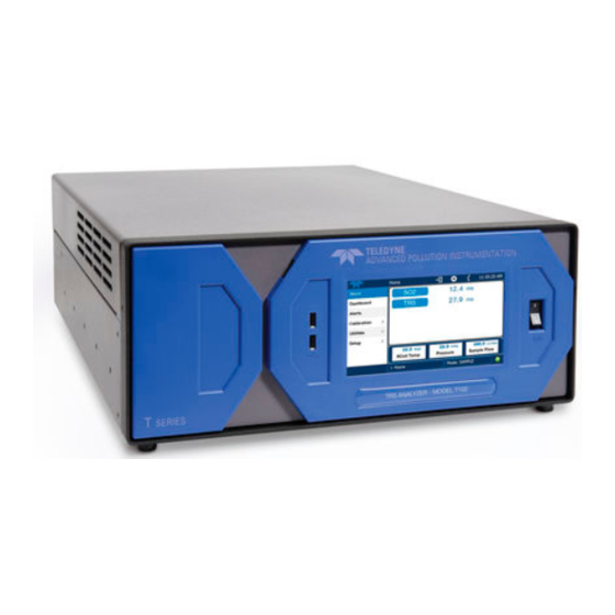
TOTAL REDUCED SULFUR ANALYZER with THERMAL CONVERTER
Brand:
Teledyne
| Category:
Measuring Instruments
| Size: 4.5 MB
Table of Contents
Table of Contents
11
1 Introduction
15
Reference Numbering Convention
16
2 Specifications and Approvals
17
Specifications
17
M501-TRS Specifications
17
EPA Equivalency Designation
17
Table 2-1: Model 501 Basic Unit Specifications
17
CE Mark Compliance
18
3 Getting Started
19
Unpacking the T102
19
Unpacking the M501-TRS
19
M501-TRS Ventilation Clearance
19
Internal Layouts
21
Figure 3-1. T102 Internal Layout
21
T102 and M501-TRS Internal Pneumatic Flow
22
Figure 3-2. M501-TRS Internal Layout
22
Figure 3-3. Internal Pneumatic Diagram of the T102 Standard Configuration
23
Table 3-1. TRS - so
23
Rear Panel Layout for the T102 & M501-TRS
24
Figure 3-4. T102 Rear Panel (with Zero Air Scrubber Attached)
24
Figure 3-5. M501-TRS Rear Panel Layout
24
Initial Setup
25
Electrical Connections
25
T102 Analog Output Connections
25
Figure 3-6. Analog Output Connector
25
Table 3-2. Analog Output Pin Outs
25
M501-TRS Alarm Output Connections
26
4 Pneumatic Connections
27
Table 4-1. Table 3-3: Inlet / Outlet Connector Labels and Functions
27
Figure 4-1. Pneumatic Connections-Basic Configuration-Using Gas Dilution Calibrator
28
Figure 4-2. Pneumatic Connections-Basic Configuration-Using Bottled Span Gas
28
Connections with Internal Valve Options Installed
30
Figure 4-3. Basic Pneumatic Connections for Units with Zero/Span Valve Option
30
Table 4-2. NIST-Srm's Available for Traceability of H2S & SO2 Calibration Gases
30
Figure 4-4. Pneumatic Connections for Formal Calibration of Units W/ IZS Valve Option
31
Initial Operation
32
Startup / Warm up of the T102
32
Functional Check of the T102
32
Startup / Warm up of the M501-TRS
33
Figure 4-6. M501-TRS Temperature Controller Startup
33
Initial Calibration
34
5 Optional Hardware and Software
35
Rack Mount Kits (Options 20A, 20B, 21, 22 & 81)
35
Calibration Valves Options
35
Zero/Span Valves (Option 50) & Internal Zero/Span Gas Generator (Option 51)
35
Figure 5-1. Internal Pneumatic Diagram of the T102 with Z/S Option Installed
36
Table 5-1. Zero/Span Valve Operating States
36
Figure 5-2. Internal Pneumatic Diagram of the T102 with IZS Options Installed
37
Table 5-2. IZS Valve Operating States
37
6 T102 Operating Instructions
39
T102 Analog Output Signals
39
Figure 6-1. Analog Output Connector
39
Setting the T102 Gas Measurement Mode
40
SETUP - DIAG: Using the Diagnostics Functions
40
T102 Analog I/O Configuration
40
Table 6-1. T102 Gas Measurement Modes
40
Table 6-2. Analog Output Pin Assignments
40
T102 Test Channel Output
41
SETUP - COMM: Setting up the T102'S Communication Ports
41
T102 ID Code
41
T102 Ethernet Host Name
41
Table 6-3. Test Parameters Available for Analog Output A4
41
Remote Operation of the Analyzer
42
Control Inputs
42
Figure 6-2. Control Inputs with Local 5 V Power Supply
42
Table 6-4. T102 Control Input Pin Assignments
42
Using the T102 with a Hessen Protocol Network
43
T102 Hessen Protocol Gas ID List
43
Figure 6-3. Control Inputs with External 5 V Power Supply
43
Table 6-5. T102 Default Hessen Gas ID's
43
Setting Hessen Protocol Status Flags
44
Table 6-6. Default Hessen Status Bit Assignments
44
7 M501-Trs Operating Instructions
45
Basic M501-TRS Controls
45
Figure 7-1. M501-TRS Temperature Controls
45
Table 7-1. M501-TRS Temperature Controls and Definitions
46
To Display the Current Temperature
47
To Manually Adjust the Converter Oven Temperature
47
Autotune the Temperature Controller
48
Initiating the Autotune Process
48
Aborting the Autotune Process
49
M501TRS Alarm Relay Adjustment
49
8 Calibration Procedures
51
T102 Calibration
51
M501-TRS Calibration
51
Table 8-1. T102 Preventive Maintenance Schedule
53
Additional and Updated Maintenance Procedures
55
Maintaining the so Scrubber
55
Predicting When to Replace the so Scrubber
55
Checking the Function of the so Scrubber
56
Changing the so Scrubber Material
56
10 Theory of Operation
57
Measurement Principle
57
TRS Conversion
57
SO Ultraviolet Fluorescence
58
Figure 10-1. UV Absorption in the T102 Reaction Cell
58
The UV Light Path
60
UV Lamp Shutter & PMT Offset
60
Pneumatic Operation
61
Sample Gas Flow
61
M501 so Scrubber
61
Electronic Operation
62
Sensor Module
62
Figure 10-2. T102 Sensor Module
62
Figure 10-3. T102 Sample Chamber
63
Sample Chamber
63
Sample Chamber Heating Circuit
63
M501-TRS Electronics
64
Thermal Switch
64
Figure 10-4. M501-TRS Electronic Block Diagram
64
Temperature Alarms and Alarm Output
65
11 Troubleshooting and Repair
67
Fault Diagnosis with Warning Messages
67
T102 Warning Messages
67
M501-TRS Error Codes
67
Fault Diagnosis with Test Functions
68
Table 11-1. Test Functions - Possible Causes for Out-Of-Range Values
68
Table 11-2. Test Functions - Possible Causes for Out-Of-Range Values
68
M501-TRS Troubleshooting
69
TRS Converter Not Heating
69
Other Performance Problems
70
Excessive Noise
70
Subsystem Checkout
70
Checking the Efficiency of the M501-TRS so
70
Checking the Efficiency of the M501-TRS TRS so
70
Scrubber
70
Converter
70
Additional Repair Procedures
72
UV Lamp Adjustment And/Or Replacement
73
Adjusting the UV Lamp (Peaking the Lamp)
73
Replacing the UV Lamp
74
Figure 11-1. Shutter Assembly - Exploded View
74
Replacing the UV Filter/Lens
75
Figure 11-2. Disassembling the Shutter Assembly
75
Replacing the PMT, HVPS or TEC
76
Figure 11-3. PMT Assembly - Exploded View
76
T102 PMT Hardware Calibration (FACTORY CAL)
79
Figure 11-4. Pre-Amplifier Board Layout
80
Replacing the TRS Converter Heating Tube
82
Replacing the Thermocouple
83
Figure 11-5. Thermocouple
84
Figure 11-6. Cavity for Thermocouple
84
Figure 11-7. Thermocouple Installed
85
Figure 11-8. Tie-Wrap Hold-Down Location
85
Manually Programming the M501-TRS Temperature Controller
86
Temperature Controller Primary Menu Parameters
87
Table 11-3. Temperature Controller - Primary Parameter Settings
88
Technical Assistance
89
Table 11-4. Temperature Controller - Secondary Parameter Settings
89
Advertisement
Advertisement
Related Products
Teledyne T100
Teledyne t108u
Teledyne t100h
Teledyne t108
Teledyne t100u
Teledyne T101
Teledyne TED 191
Teledyne T200U
Teledyne T265
TELEDYNE T200H
Teledyne Categories
Measuring Instruments
Analytical Instruments
Digital Camera
Test Equipment
Laboratory Equipment
More Teledyne Manuals
Login
Sign In
OR
Sign in with Facebook
Sign in with Google
Upload manual
Upload from disk
Upload from URL