Sign In
Upload
Manuals
Brands
Suzuki Manuals
Automobile
Grand Vitara 2005
Suzuki Grand Vitara 2005 Manuals
Manuals and User Guides for Suzuki Grand Vitara 2005. We have
4
Suzuki Grand Vitara 2005 manuals available for free PDF download: Owner's Manual, Service Manual, Manual
Suzuki Grand Vitara 2005 Owner's Manual (1736 pages)
GRAND VITARA
Brand:
Suzuki
| Category:
Automobile
| Size: 68.83 MB
Table of Contents
Table of Contents
5
Precautions
7
Air Bag Locations
8
Precautions
8
Precautions for Vehicles Equipped with a Supplemental Restraint (Air Bag) System
8
Diagnosis, Servicing and Handling
9
General Precautions
11
Precaution in Servicing Full-Time 4WD Vehicle
14
Precautions for Catalytic Converter
15
Precaution for CAN Communication System
16
Precautions for Electrical Circuit Service
16
Precautions for Installing Mobile Communication Equipment
18
Air Bag Warning
18
Discharge Headlight Warning
18
A/C System Caution
18
Fastener Caution
18
Suspension Caution
19
Wheels and Tires Caution
19
Brakes Caution and Note
19
Differential Gear Oil Note
19
Repair Instructions
19
Electrical Circuit Inspection Procedure
19
Intermittent and Poor Connection Inspection
22
General Information
23
General Information
24
General Description
24
Abbreviations
24
Symbols
25
Wire Color Symbols
26
Fastener Information
26
General Information
27
Vehicle Lifting Points
28
Engine Supporting Points
30
Vehicle Identification Number
30
Engine Identification Number
30
Transmission Identification Number
30
Component Location
31
Warning, Caution and Information Label Location
31
Maintenance and Lubrication
33
Precautions
33
Precautions for Maintenance and Lubrication
33
Scheduled Maintenance
33
Maintenance Schedule under Normal Driving Conditions
33
Maintenance Recommended under Severe Driving Conditions
34
Repair Instructions
36
Engine Accessory Drive Belt Inspection
36
Engine Accessory Drive Belt Replacement
36
Valve Lash (Clearance) Inspection
36
Engine Oil and Filter Change
37
Engine Coolant Change
38
Exhaust System Inspection
39
Spark Plugs Replacement
39
Air Cleaner Filter Inspection
39
Air Cleaner Filter Replacement
39
Fuel Lines and Connections Inspection
39
Fuel Filter Replacement
39
Fuel Tank Inspection
39
Crankcase Ventilation Hoses and Connections Inspection (Vehicle Without A/F Sensor)
39
PCV Valve Inspection
39
Fuel Evaporative Emission Control System Inspection
40
Brake Discs and Pads Inspection
40
Brake Drums and Shoes Inspection
40
Brake Hoses and Pipes Inspection
40
Brake Fluid Change
40
Parking Brake Lever and Cable Inspection
41
Clutch Fluid Inspection
41
Tire / Wheel Inspection and Rotation
41
Wheel Discs Inspection
42
Wheel Bearing Inspection
42
Suspension System Inspection
42
Steering System Inspection
42
Propeller Shafts and Drive Shafts Inspection
43
Manual Transmission Oil Inspection
43
Manual Transmission Oil Change
43
Automatic Transmission Fluid Inspection
43
Automatic Transmission Fluid Change
44
Automatic Transmission Fluid Cooler Hose Inspection
44
Transfer Oil Inspection (if Equipped)
44
Differential Oil Inspection
44
Transfer (if Equipped) and Differential Oil Change
44
Power Steering (P/S) System Inspection
45
All Hinges, Latches and Locks Inspection
45
HVAC Air Filter Inspection (if Equipped)
45
HVAC Air Filter Replacement (if Equipped)
45
Final Inspection for Maintenance Service
45
Specifications
47
Tightening Torque Specifications
47
Special Tools and Equipment
47
Recommended Fluids and Lubricants
47
Special Tool
47
Engine
49
Precautions
55
Precautions for Engine
55
Engine General Information and Diagnosis
56
Precautions
56
Precautions on Engine Service
56
Precautions in Diagnosing Trouble
56
Precautions for DTC Troubleshooting
57
Precautions of ECM Circuit Inspection
57
Precautions of Electric Throttle Body System Calibration
57
General Description
57
Statement on Cleanliness and Care
57
Engine Diagnosis General Description
58
On-Board Diagnostic System Description
58
Engine and Emission Control System Description
61
CAN Communication System Description
61
Air Intake System Description
64
Description of Electric Throttle Body System
65
Description of Electric Throttle Body System Calibration
66
Generator Control System Description
66
A/F Sensor Description
67
Electronic Control System Description
68
Engine and Emission Control Input / Output Table
76
Schematic and Routing Diagram
77
Engine and Emission Control System Diagram
77
Component Location
78
Electronic Control System Components Location
78
Diagnostic Information and Procedures
80
Engine and Emission Control System Check
80
Malfunction Indicator Lamp (MIL) Check
83
DTC Check
83
DTC Clearance
84
DTC Table
85
Fail-Safe Table
91
Scan Tool Data
92
Visual Inspection
98
Engine Basic Inspection
99
Engine Symptom Diagnosis
103
Malfunction Indicator Lamp Does Not Come on with Ignition Switch on and Engine Stop (but Engine Can be Started)
112
Wiring Diagram
112
Malfunction Indicator Lamp Remains on after Engine Starts
114
DTC P0010: Camshaft Position Actuator Circuit (for M16 Engine)
115
DTC P0011 / P0012: Camshaft Position - Timing Over-Advanced or System Performance / -Retarded (for M16 Engine)
117
DTC P0030: HO2S Heater Control Circuit (Sensor-1)
119
DTC P0031 / P0032: HO2S Heater Control Circuit Low / High (Sensor-1)
120
DTC P0037 / P0038: HO2S Heater Control Circuit Low / High (Sensor-2)
124
DTC P0101: Mass Air Flow Circuit Range / Performance
127
DTC P0102: Mass Air Flow Circuit Low Input
130
DTC P0103: Mass Air Flow Circuit High Input
132
DTC P0106: Manifold Absolute Pressure Range / Performance
134
DTC P0107: Manifold Absolute Pressure Circuit Low Input
135
DTC P0108: Manifold Absolute Pressure Circuit High Input
137
DTC P0111: Intake Air Temperature Circuit Range / Performance
139
DTC P0112: Intake Air Temperature Sensor Circuit Low
142
DTC P0113: Intake Air Temperature Sensor Circuit High
144
DTC P0116: Engine Coolant Temperature Circuit Range / Performance
146
DTC P0117: Engine Coolant Temperature Circuit Low
149
DTC P0118: Engine Coolant Temperature Circuit High
150
DTC P0122: Throttle Position Sensor (Main) Circuit Low
153
DTC P0123: Throttle Position Sensor (Main) Circuit High
156
DTC P0131 / P0132 / P0134: O2 Sensor (HO2S) Circuit Low Voltage / High Voltage / no Activity Detected (Sensor-1)
159
DTC P0133: O2 Sensor (HO2S) Circuit Slow Response (Sensor-1)
160
DTC P0137 / P0138: O2 Sensor (HO2S) Circuit Low Voltage / High Voltage (Sensor-2)
162
DTC P0140: O2 Sensor (HO2S) Circuit no Activity Detected (Sensor-2)
165
DTC P0171 / P0172 / P2195 / P2196: Fuel System too Lean / Rich / Stuck Lean / Stuck Rich
166
DTC P0222: Throttle Position Sensor (Sub) Circuit Low
170
DTC P0223: Throttle Position Sensor (Sub) Circuit High
173
DTC P0300 / P0301 / P0302 / P0303 / P0304: Random Misfire Detected / Cylinder 1 / Cylinder 2 / Cylinder 3 / Cylinder 4 Misfire Detected
176
DTC P0327 / P0328: Knock Sensor Circuit Low / High
178
DTC P0335: Crankshaft Position (CKP) Sensor Circuit (for J20 Engine)
180
Dtc Confirmation Procedure
180
DTC P0335: Crankshaft Position (CKP) Sensor Circuit (for M16 Engine)
182
DTC P0340: Camshaft Position (CMP) Sensor Circuit
185
DTC P0401 / P0402: Exhaust Gas Recirculation Flow Insufficient Detected / Excessive Detected
188
DTC P0403: Exhaust Gas Recirculation Control Circuit
191
DTC P0420: Catalyst System Efficiency below Threshold
193
DTC P0443: Evaporative Emission System Purge Control Valve Circuit
195
DTC P0462: Fuel Level Sensor Circuit Low
197
DTC P0463: Fuel Level Sensor Circuit High
199
DTC P0480: Fan 1 (Radiator Cooling Fan) Control Circuit
201
DTC P0500: Vehicle Speed Sensor (VSS) Malfunction
205
DTC P0504: Brake Switch "A"/"B" Correlation (for J20 Engine)
207
DTC P0532: A/C Refrigerant Pressure Sensor Circuit Low
209
DTC P0533: A/C Refrigerant Pressure Sensor Circuit High
211
DTC P0601 / P0602 / P0607: Internal Control Module Memory Check Sum Error / Control Module Programming Error / Control Module Performance
212
DTC P0616: Starter Relay Circuit Low
213
DTC P0617: Starter Relay Circuit High
215
DTC P0620: Generator Control Circuit
216
DTC P0625 / P0626: Generator Field Terminal Circuit Low / High
218
DTC P0660: Intake Manifold Tuning Valve Control Circuit / Open (for J20 Engine)
220
DTC P1501 / P1502: Electric Load Current Sensor Circuit Low / High
222
DTC P1510: ECM Back-Up Power Supply Malfunction
224
DTC P1603: TCM Trouble Code Detected (for J20 Engine)
225
DTC P1674: CAN Communication (Bus off Error)
226
DTC P1676: CAN Communication (Reception Error for TCM (for A/T Model))
231
DTC P1678: CAN Communication (Reception Error for BCM)
235
DTC P1685: CAN Communication (Reception Error for ABS Control Module)
239
DTC P2101: Throttle Actuator Control Motor Circuit Range / Performance
242
DTC P2102: Throttle Actuator Control Motor Circuit Low
244
DTC P2103: Throttle Actuator Control Motor Circuit High
246
DTC P2111: Throttle Actuator Control System - Stuck Open
247
DTC P2119: Throttle Actuator Control Throttle Body Range / Performance
248
DTC P2122: Pedal Position Sensor (Main) Circuit Low Input
250
DTC P2123: Pedal Position Sensor (Main) Circuit High Input
253
DTC P2127: Pedal Position Sensor (Sub) Circuit Low Input
255
DTC P2128: Pedal Position Sensor (Sub) Circuit High Input
257
DTC P2135: Throttle Position Sensor (Main / Sub) Voltage Correlation
260
DTC P2138: Pedal Position Sensor (Main / Sub) Voltage Correlation
263
DTC P2227 / P2228 / P2229: Barometric Pressure Circuit Malfunction
265
Inspection of ECM and Its Circuits
267
ECM Power and Ground Circuit Check
289
Fuel Injector Circuit Check
293
Fuel Pump and Its Circuit Check
295
Fuel Pressure Check
298
A/C System Circuits Check
300
Electric Load Signal Circuit Check
303
Radiator Cooling Fan Low Speed Control System Check
305
Troubleshooting
305
Radiator Cooling Fan High Speed Control System Check
308
Repair Instructions
310
Idle Speed and IAC Throttle Valve Opening Inspection
310
Special Tools and Equipment
311
Special Tool
311
Aux. Emission Control Devices
312
Diagnostic Information and Procedures
312
EGR System Inspection
312
Repair Instructions
312
EVAP Canister Purge Inspection
312
EVAP Canister Purge Valve and Its Circuit Inspection
313
Vacuum Passage Inspection
313
Vacuum Hose and Purge Valve Chamber Inspection
314
EVAP Canister Purge Valve Inspection
314
EVAP Canister Inspection
315
EGR Valve Removal and Installation
315
EGR Valve Inspection
315
PCV Hose Inspection
315
PCV Valve Removal and Installation
316
PCV Valve Inspection
316
Specifications
317
Tightening Torque Specifications
317
Special Tools and Equipment
317
Recommended Service Material
317
Special Tool
317
Engine Electrical Devices
318
Repair Instructions
318
Engine Control Module (ECM) Removal and Installation
318
Manifold Absolute Pressure (MAP) Sensor Inspection
318
Electric Throttle Body Assembly On-Vehicle Inspection
319
Electric Throttle Body System Calibration
321
Accelerator Pedal Position (APP) Sensor Assembly On-Vehicle Inspection
322
Accelerator Pedal Position (APP) Sensor Assembly Removal and Installation
322
Accelerator Pedal Position (APP) Sensor Assembly Inspection
323
Engine Coolant Temperature (ECT) Sensor Removal and Installation
323
Engine Coolant Temperature (ECT) Sensor Inspection
324
Air Fuel Ratio (A/F) Sensor On-Vehicle Inspection
324
Heated Oxygen Sensor (HO2S-2) Heater On-Vehicle Inspection
325
Air Fuel Ratio (A/F) Sensor, Heated Oxygen Sensor (HO2S-2) Removal and Installation
325
Camshaft Position (CMP) Sensor Removal and Installation
325
Camshaft Position (CMP) Sensor Inspection
326
Crankshaft Position (CKP) Sensor Removal and Installation
326
Crankshaft Position (CKP) Sensor Inspection
327
Knock Sensor Removal and Installation
328
Control Relay Inspection
329
Mass Air Flow (MAF) and Intake Air Temperature (IAT) Sensor On-Vehicle Inspection
330
Mass Air Flow (MAF) and Intake Air Temperature (IAT) Sensor Removal and Installation
330
Mass Air Flow (MAF) and Intake Air Temperature (IAT) Sensor Inspection
331
Vacuum Tank Assembly Inspection (for J20 Engine)
331
Electric Load Current Sensor On-Vehicle Inspection (for J20 Engine)
333
Electric Load Current Sensor Removal and Installation (for J20 Engine)
333
Specifications
334
Engine Mechanical
335
For M16A Engine with VVT
335
General Description
335
Engine Construction Description
335
Camshaft Position Control (VVT Variable Valve Timing) System Description
336
Diagnostic Information and Procedures
338
Compression Check
338
Engine Vacuum Check
339
Valve Lash (Clearance) Inspection
340
Repair Instructions
342
Air Cleaner Filter Removal and Installation
342
Air Cleaner Filter Inspection and Cleaning
343
Cylinder Head Cover Removal and Installation
343
Throttle Body and Intake Manifold Components
345
Throttle Body On-Vehicle Inspection
345
Electric Throttle Body Assembly Removal and Installation
346
Throttle Body Cleaning
346
Intake Manifold Removal and Installation
347
Engine Mountings Components
348
Engine Assembly Removal and Installation
348
Timing Chain Cover Components
352
Timing Chain Cover Removal and Installation
353
Timing Chain Cover Inspection
355
Oil Control Valve Removal and Installation
355
Oil Control Valve Inspection
356
Timing Chain and Chain Tensioner Components
357
Timing Chain and Chain Tensioner Removal and Installation
357
Timing Chain and Chain Tensioner Inspection
360
Camshaft, Tappet and Shim Components
361
Camshaft, Tappet and Shim Removal and Installation
361
Camshaft, Tappet and Shim Inspection
364
Valves and Cylinder Head Components
367
Valves and Cylinder Head Removal and Installation
368
Valves and Cylinder Head Disassembly and Assembly
369
Valves and Valve Guides Inspection
372
Cylinder Head Inspection
374
Valve Spring Inspection
375
Pistons, Piston Rings, Connecting Rods and Cylinders Components
376
Pistons, Piston Rings, Connecting Rods and Cylinders Removal and Installation
376
Pistons, Piston Rings, Connecting Rods and Cylinders Disassembly and Assembly
378
Cylinders, Pistons and Piston Rings Inspection
379
Piston Pins and Connecting Rods Inspection
381
Crank Pin and Connecting Rod Bearings Inspection
382
Main Bearings, Crankshaft and Cylinder Block Components
386
Main Bearings, Crankshaft and Cylinder Block Removal and Installation
387
Crankshaft Inspection
390
Main Bearings Inspection
391
Sensor Plate Inspection
395
Rear Oil Seal Inspection
395
Flywheel Inspection
396
Cylinder Block Inspection
396
Specifications
397
Tightening Torque Specifications
397
Special Tools and Equipment
398
Recommended Service Material
398
Special Tool
398
For J20 Engine
400
General Description
400
Engine Construction Description
400
Air Cleaner Element Introduction
402
IMT (Intake Manifold Tuning) System
402
Diagnostic Information and Procedures
404
Compression Check
404
Engine Vacuum Check
405
Valve Lash (Clearance) Inspection
406
Repair Instructions
409
Air Cleaner Assembly Removal and Installation
409
Air Cleaner Filter Removal and Installation
409
Air Cleaner Filter Inspection and Cleaning
409
Throttle Body and Intake Manifold Components
410
Throttle Body On-Vehicle Inspection
410
Electric Throttle Body Assembly Removal and Installation
410
Throttle Body Cleaning
411
Intake Manifold Removal and Installation
411
Cylinder Head Cover Removal and Installation
412
Engine Mountings Components
414
Engine Assembly Removal and Installation
415
Timing Chain Cover Components
418
Timing Chain Cover Removal and Installation
418
Timing Chain Cover Cleaning and Inspection
421
2Nd Timing Chain and Chain Tensioner Components
421
Tightening Torque
421
2Nd Timing Chain and Chain Tensioner Removal and Installation
422
2Nd Timing Chain and Chain Tensioner Inspection
424
1St Timing Chain and Chain Tensioner Components
425
Camshaft Sprocket
425
1St Timing Chain and Chain Tensioner Removal and Installation
426
1St Timing Chain and Chain Tensioner Inspection
428
Camshafts, Tappet and Shim Components
429
Camshafts, Tappet and Shim Removal and Installation
429
Camshaft, Tappet and Shim Inspection
431
Valves and Cylinder Head Components
433
Valves and Cylinder Head Removal and Installation
433
Valves and Cylinder Head Disassembly and Assembly
435
Valves and Valve Guides Inspection
438
Cylinder Head Inspection
440
Valve Spring Inspection
441
Pistons, Piston Rings, Connecting Rods and Cylinders Components
442
Pistons, Piston Rings, Connecting Rods and Cylinders Removal and Installation
442
Pistons, Piston Rings, Connecting Rods and Cylinders Disassembly and Assembly
443
Pistons, Piston Rings, Connecting Rods and Cylinders Inspection and Cleaning
446
Main Bearings, Crankshaft and Cylinder Block Components
452
Main Bearings, Crankshaft and Cylinder Block Removal and Installation
453
Main Bearings, Crankshaft and Cylinder Block Inspection
456
Specifications
463
Tightening Torque Specifications
463
Special Tools and Equipment
464
Recommended Service Material
464
Special Tool
464
Engine Lubrication System
467
For M16A Engine with VVT
467
General Description
467
Engine Lubrication Description
467
Diagnostic Information and Procedures
469
Oil Pressure Check
469
Repair Instructions
470
Oil Pan and Oil Pump Strainer Components
470
Oil Pan and Oil Pump Strainer Removal and Installation
471
Oil Pan and Oil Pump Strainer Cleaning
472
Oil Pump Components
473
Oil Pump Removal and Installation
473
Oil Pump Disassembly and Reassembly
473
Oil Pump Inspection
474
Specifications
476
Tightening Torque Specifications
476
Special Tools and Equipment
476
Recommended Service Material
476
Special Tool
476
For J20 Engine
477
General Description
477
Engine Lubrication Description
477
Diagnostic Information and Procedures
479
Oil Pressure Check
479
Repair Instructions
480
Oil Pan and Oil Pump Strainer Components
480
Oil Pan and Oil Pump Strainer Removal and Installation
481
Oil Pan and Oil Pump Strainer Cleaning
482
Oil Pump Components
482
Oil Pump Removal and Installation
483
Oil Pump Disassembly and Assembly
483
Oil Pump Inspection
484
Special Tools and Equipment
486
Recommended Service Material
486
Special Tool
486
Engine Cooling System
487
General Description
487
Cooling System Description
487
Coolant Description
487
Schematic and Routing Diagram
488
Coolant Circulation
488
Diagnostic Information and Procedures
489
Engine Cooling Symptom Diagnosis
489
Repair Instructions
490
Cooling System Components
490
Coolant Level Check
492
Engine Cooling System Inspection and Cleaning
492
Cooling System Draining
493
Cooling System Flush and Refill
493
Cooling Water Pipes or Hoses Removal and Installation
494
Thermostat Removal and Installation
494
Thermostat Removal and Installation
495
Thermostat Inspection
495
Radiator Cooling Fan Motor On-Vehicle
496
Inspection
496
Radiator Cooling Fan Relay Inspection
496
Radiator Cooling Fan Assembly Removal and Installation
497
Radiator On-Vehicle Inspection and Cleaning
497
Radiator Removal and Installation
498
Water Pump Removal and Installation
498
Water Pump Removal and Installation
499
Water Pump Inspection
500
Specifications
500
Tightening Torque Specifications
500
Special Tools and Equipment
500
Recommended Service Material
500
Fuel System
501
Precautions
501
Precautions on Fuel System Service
501
General Description
501
Fuel System Description
501
Fuel Delivery System Description
501
Fuel Pump Description
502
Schematic and Routing Diagram
502
Fuel Delivery System Diagram
502
Diagnostic Information and Procedures
503
Fuel Pressure Inspection
503
Fuel Cut Operation Inspection
504
Repair Instructions
505
Fuel System Components
505
Fuel Hose Disconnecting and Reconnecting
508
Fuel Pressure Relief Procedure
510
Fuel Leakage Check Procedure
510
Fuel Lines On-Vehicle Inspection
511
Fuel Pipe Removal and Installation
511
Fuel Injector Removal and Installation
512
Fuel Injector Inspection
513
Fuel Pressure Regulator Removal and Installation
515
Fuel Pressure Regulator Inspection
515
Fuel Filler Cap Inspection
516
Fuel Tank Inlet Valve Removal and Installation
516
Fuel Tank Inlet Valve Inspection
517
Fuel Tank Removal and Installation
517
Fuel Tank Inspection
519
Fuel Tank Purging Procedure
519
Fuel Pump On-Vehicle Inspection
519
Fuel Pump Assembly Removal and Installation
520
Main Fuel Level Sensor Removal and Installation
521
Fuel Pump Inspection
521
Sub Fuel Level Sensor Removal and Installation
521
Sub Fuel Level Sensor Inspection
522
Specifications
522
Tightening Torque Specifications
522
Special Tools and Equipment
523
Recommended Service Material
523
Special Tool
523
Ignition System
524
General Description
524
Ignition System Construction
524
Component Location
526
Ignition System Components Location
526
Diagnostic Information and Procedures
527
Ignition System Symptom Diagnosis
527
Reference Waveform of Ignition System
527
Ignition System Check
527
Ignition Spark Test
527
Repair Instructions
530
High-Tension Cord Inspection
530
Spark Plug Removal and Installation
530
Spark Plug Inspection
531
Ignition Coil Assembly (Including Ignitor) Removal and Installation
531
Ignition Coil Assembly (Including Ignitor) Inspection
532
Ignition Timing Inspection
532
Specifications
534
Tightening Torque Specifications
534
Special Tools and Equipment
534
Starting System
535
Precautions
535
Advertisement
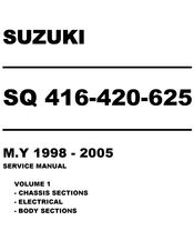
Suzuki Grand Vitara 2005 Service Manual (801 pages)
Brand:
Suzuki
| Category:
Automobile
| Size: 12.74 MB
Table of Contents
Section 0A General Information
4
Table of Contents
4
How to Use this Manual
5
Precautions
6
Precautions for Vehicle Equipped with a Supplemental Restraint (Air Bag) System
6
Diagnosis
6
Servicing and Handling
7
General Precautions
10
Precautions for Catalytic Converter
12
Precautions for Electrical Circuit Service
13
Electrical Circuit Inspection Procedure
15
Intermittent and Poor Connection
18
Precaution for Installing Mobile Communication Equipment
19
Identification Information
20
Body Number
20
Engine Identification Number
20
Transmission Identification Number
20
Warning, Caution and Information Labels
21
Vehicle Lifting Points
22
Abbreviations May be Used in this Manual
24
Metric Information
26
Metric Fasteners
26
Fasteners Strength Identification
26
Standard Tightening Torque
27
Maintenance and Lubrication
28
Maintenance Schedule
29
0B-2 Maintenance and Lubrication
29
Maintenance Schedule under Normal Driving Conditions
29
Maintenance Recommended under Severe Driving Conditions
31
Maintenance Service
32
Engine
32
Ignition System
39
Fuel System
39
Emission Control System
41
Chassis and Body
42
Final Inspection
51
Recommended Fluids and Lubricants
52
Heater and Ventilation
53
General Description
54
Body Ventilation
55
Diagnosis
55
Diagnosis Table
55
Wiring Circuit
56
On-Vehicle Service
57
Blower Unit
57
Blower Motor
59
Blower Motor Relay
60
Blower Motor Resistor
61
Heater Mode Control Switch
62
Heater Mode Control Actuator
64
Heater Control Lever Assembly
66
Heater Control Cables
67
Heater Unit
68
Rear Duct
71
Section 1B Air Conditioning (Optional)
72
General Description
74
Identification of Refrigerating System
74
Refrigerant Flow of Air Conditioning System
75
Major Components and Location
76
Diagnosis
77
General
77
Diagnosis of Abnormal Noise
79
Quickly Checking of Refrigerant Charge
81
(If Equipped with Sight Glass)
81
Compression System Diagnosis
82
Performance Diagnosis
83
Wiring Circuit
87
Inspection of A/C Controller and Its Circuits
89
Drive Belt
93
Refrigerant Recovery, Evacuation and Charging
94
Operation Procedure for Charging A/C with Refrigerant
94
Recovery
95
Evacuating
96
Charging
97
Removing Manifold Gauge Set
100
Leak-Testing Refrigerant System
100
Liquid Leak Detectors
100
On-Vehicle Service
101
Precaution
101
A/C Condenser Assembly
104
Condenser Cooling Fan Assembly
106
Condenser Dryer (Receiver/Dryer)
107
Air Filter Element
108
Cooling Unit (Evaporator)
110
Expansion Valve
113
A/C Evaporator Thermistor (Evaporator Temperature Sensor)
114
Refrigerant Pipes and Hoses
115
A/C Switch
116
A/C Controller
117
Dual Pressure Switch
118
A/C Compressor Relay and A/Ccondenser Cooling Fan Relay
119
Compressor Assembly
120
Magnet Clutch Assembly
124
Magnet Clutch Assembly
127
Lip Type Seal (for Seiko Seiki)
130
Required Service Material
132
Special Tools
132
Wheels and Tires
133
Section 3B1 Power Steering (P/S) System
145
General Description
146
Power Steering System
146
Steering Gear Box
147
Power Steering (P/S) Pump
148
Diagnosis
149
General Diagnosis Table
149
Power Steering Fluid
151
Power Steering Fluid Level Check
151
Steering Wheel
151
Steering Force Check
151
Steering Wheel Play Check
151
Power Steering Pump Drive Belt
152
Belt Tension Adjustment
152
Belt Tension Check
152
Fluid
153
Fluid Leakage Check
153
Idle up System
153
Idle up System Check
153
Hydraulic Pressure in P/S Circuit
154
Hydraulic Pressure Check
154
Boot
155
Steering Rack Boot Check
155
Tie-Rod End Boot Check
156
Air Bleeding Procedure
156
On-Vehicle Service
157
Tie-Rod End
157
Power Steering Gear Box Assembly
158
Rack Boot and Tie-Rod (Except Canvas Top LH Model)
160
Rack Boot and Tie-Rod (for Canvas Top LH Model)
161
Power Steering Pump
163
Special Tool
170
Required Service Material
170
Tightening Torque Specification
170
Section 3C Steering Wheel and Column (Not Equipped with Air Bag)
171
Diagnosis
172
Inspection and Repair Required after Accident
172
General Description
172
On-Vehicle Service
173
Steering Wheel
173
Combination Switch
174
Steering Column Assembly
175
Steering Lock Assembly (Ignition Switch)
180
Steering Lower Shaft Assembly
181
Checking Steering Column for Accident Damage
183
Adjustable Steering Column Release Lever
184
Tightening Torque Specifications
184
Special Tool
184
Section 3C1 Air Bag Steering Wheel and Column
185
General Description
186
On-Vehicle Service
187
Service Precautions
187
Diagnosis and Servicing
187
Disabling Air Bag System
187
Disposal
187
Enabling Air Bag System
187
Handling and Storage
187
Driver Air Bag (Inflator) Module
188
Steering Wheel
190
Centering Contact Coil
190
Contact Coil and Combination Switch Assembly
191
Steering Column
193
Steering Lock Assembly (Ignition Switch)
198
Steering Lower Shaft Assembly
199
Checking Steering Column for Accident Damage
201
Adjustable Steering Column Release Lever
202
Diagnosis
187
Inspection and Repair Required after Accident
187
Special Tool
202
Tightening Torque Specifications
202
Suzuki Grand Vitara 2005 Service Manual (752 pages)
Brand:
Suzuki
| Category:
Automobile
| Size: 27.31 MB
Table of Contents
Precautions
7
Table of Contents
7
Precautions
8
General Precautions
8
Precaution for Vehicle Equipped with ESP® System
11
Precautions for Catalytic Converter and Diesel Particulate Filter
11
Section 1 Engine
27
Air Bag Warning
32
Precaution for CAN Communication System
32
Precautions for Electrical Circuit Service
32
Engine General Information and
33
Engine Diagnosis General Description
34
Statement on Cleanliness and Care
34
CAN Communication System Description
36
Electronic Control System Description
38
Diesel Particulate Filter Regeneration Description
43
Electronic Control System Components Location
44
Injection Warning Light (Gravity 1 Fault) Check
45
Malfunction Indicator Lamp (MIL) Check
45
Red Stop Warning Light (Gravity 2 Fault) Check
45
Engine and Emission Control System
46
DTC Check
48
DTC Clearance
48
Indicator Lamp Operation Table
52
Scan Tool Data
55
Engine Basic Inspection
57
Visual Inspection
57
DTC P0016: Crankshaft Position-Camshaft Position Correlation Malfunction
58
DTC P0033: Turbo Charger Bypass Valve Control Circuit Malfunction
59
DTC P0089: Fuel Pressure Regulator 1 Performance Malfunction
60
DTC P0100: Mass or Volume Air Flow Circuit Malfunction
64
DTC P0105: Manifold Absolute Pressure / Barometric Pressure Circuit Malfunction
66
DTC P0110: Intake Air Temperature Sensor 1 Circuit Malfunction
66
DTC P0115: Engine Coolant Temperature Circuit Malfunction
68
DTC P0190: Fuel Rail Pressure Sensor Circuit Malfunction
69
DTC P0201: Fuel Injector Circuit / Open Malfunction-Cylinder 1
70
DTC P0202: Fuel Injector Circuit / Open Malfunction-Cylinder 2
71
DTC P0203: Fuel Injector Circuit / Open Malfunction-Cylinder 3
72
DTC P0204: Fuel Injector Circuit / Open Malfunction-Cylinder 4
73
DTC P0225: Accelerator Pedal Position
74
DTC P0235: Turbo / Super Charger Boost Sensor "A" Circuit Malfunction
76
DTC P0243: Turbo / Super Charger Wastegate Solenoid "A" Malfunction
77
DTC P0297: Vehicle Overspeed Condition Malfunction
79
DTC P0301: Cylinder 1 Misfire Detected Malfunction
80
DTC P0302: Cylinder 2 Misfire Detected Malfunction
80
DTC P0303: Cylinder 3 Misfire Detected Malfunction
81
DTC P0304: Cylinder 4 Misfire Detected Malfunction
81
DTC P0335: Crankshaft Position Sensor "A" Circuit Malfunction
82
DTC P0340: Camshaft Position Sensor "A" Circuit Malfunction
83
DTC P0380: Glow Plug / Heater Circuit "A" Malfunction
84
DTC P0403: Exhaust Gas Recirculation Control Circuit Malfunction
85
DTC P0409: Exhaust Gas Recirculation Sensor "A" Circuit Malfunction
86
DTC P0470: Exhaust Pressure Sensor Malfunction
87
DTC P0480: Fan 1 Control Circuit
88
DTC P0481: Fan 2 Control Circuit
89
DTC P0486: Exhaust Gas Recirculation Sensor "B" Circuit Malfunction
90
DTC P0500: Vehicle Speed Sensor "A" Malfunction
91
DTC P0530: A/C Refrigerant Pressure Sensor "A" Circuit Malfunction
92
DTC P0544: Exhaust Gas Temperature Sensor Circuit Malfunction
93
DTC P0560: System Voltage Malfunction
94
DTC P0571: Brake Switch "A" Circuit Malfunction
95
DTC P0575: Cruise Control Input Circuit Malfunction
96
DTC P0606: ECM / PCM Processor Malfunction
96
DTC P0611: Fuel Injector Control Module Performance Malfunction
98
DTC P0615: Starter Relay Circuit Malfunction
99
DTC P0627: Fuel Pump "A" Control Circuit / Open
100
DTC P0638: Throttle Actuator Control Range / Performance Malfunction
101
DTC P0641: Sensor Reference Voltage "A" Circuit / Open Malfunction
104
DTC P0645: A/C Clutch Relay Control Circuit
106
DTC P0651: Sensor Reference Voltage "B" Circuit / Open Malfunction
107
DTC P0670: Glow Plug Module Control Circuit Malfunction
109
DTC P0685: ECM / PCM Power Relay Control Circuit / Open Malfunction
110
DTC P0697: Sensor Reference Voltage "C" Circuit / Open Malfunction
110
DTC P0830: Clutch Pedal Switch "A" Circuit Malfunction
112
DTC P1431: Clogged Particulate Filter Failures Malfunction
112
DTC P1436: Regeneration Request Failures Malfunction
113
DTC P1480: Defective Particulate Filter Inlet Pick-Off Failures Malfunction
114
DTC P1641: Additional Heater Relay No.1 Control Circuit
114
DTC P1642: Additional Heater Relay No.2 and 3 Control Circuit
115
DTC P2002: Particulate Trap Efficiency below Threshold Malfunction
116
DTC P2031: Exhaust Gas Temperature Sensor Circuit Malfunction
117
DTC P2120: Throttle/Pedal Position Sensor/Switch "D" Circuit Malfunction
118
DTC P2141: Exhaust Gas Recirculation Throttle Control Circuit Low Malfunction
120
DTC P2142: Exhaust Gas Recirculation Throttle Control Circuit High Malfunction
121
DTC P2264: Water in Fuel Sensor Circuit Malfunction
122
DTC P2413: Exhaust Gas Recirculation System Performance Malfunction
123
DTC P242A: Turbine Inlet Temperature Sensor and Wake-Up Sensor Failure Malfunction
124
DTC P242B: Turbine Inlet Temperature Sensor Regulation Failure Malfunction
125
DTC P2600: Coolant Pump Control Circuit / Open Malfunction
126
DTC P3031: Temperature Threshold Overshoot Failures During After-Sales Regeneration
127
Fault Finding-Customer Complaints
127
Fault Finding-Tests
136
Test 1: Exhaust System Check
136
Test 2: Low Pressure Circuit Check
138
Test 3: Checking the Turbocharged Air Inlet Circuit
139
Test 4: MAF Sensor
140
Test 5: Variable Geometry Turbocharger Control
141
Test 6: Rotating Part of a Turbocharger
142
Test 7: Exhaust Gas Recirculation Valve
143
Test 8: Injector Malfunction
144
Special Tool
146
Special Tools and Equipment
146
Aux. Emission Control Devices
147
EGR Valve Inspection
147
Exhaust Gas Temperature Sensor 1, 2 and 3 Removal and Installation
147
Repair Instructions
147
Diesel Particulate Filter Differential Pressure Sensor Removal and Installation
149
Exhaust Gas Temperature Sensor 1, 2 and 3 Inspection
149
Specifications
149
Tightening Torque Specifications
149
ECM Registration
150
Engine Electrical Devices
150
General Description
150
Precaution in Replacing ECM
150
Precautions
150
Engine Control Module (ECM) Removal and Installation
151
Idle Speed Inspection
151
Registration Procedure for the ECM
151
Repair Instructions
151
EGR Valve Data Initialization
152
Registration Procedure for the Fuel Injector Calibration Code
152
Diesel Particulate Filter After-Sales Regeneration Procedure
153
Diesel Particulate Filter Data Initialization
153
Inlet Throttle Valve Data Initialization
153
Glow Plug Removal and Installation
154
Accelerator Pedal Position (APP) Sensor Assembly On-Vehicle Inspection
155
Accelerator Pedal Position (APP) Sensor Assembly Removal and Installation
155
Glow Plug Inspection
155
Accelerator Pedal Position (APP) Sensor Assembly Inspection
156
Engine Coolant Temperature (ECT) Sensor Inspection
157
Engine Coolant Temperature (ECT) Sensor Removal and Installation
157
Camshaft Position (CMP) Sensor Removal and Installation
158
Crankshaft Position (CKP) Sensor (Engine Speed Sensor) Removal and Installation
158
Boost Pressure Sensor Removal and Installation
159
Crankshaft Position (CKP) (Engine Speed Sensor) Sensor Inspection
159
Main Relay and Fuel Heater Relay Inspection
159
Boost Pressure Control Solenoid Valve Removal and Installation
160
Pre-Heating Unit Removal and Installation
160
Boost Pressure Control Solenoid Valve Inspection
161
Turbocharger Electric Water Pump Inspection
161
Turbocharger Electric Water Pump Removal and Installation
161
Inlet Throttle Valve On-Vehicle Inspection
162
Inlet Throttle Valve Removal and Installation
162
Mass Air Flow (MAF) and Intake Air Temperature (IAT) Removal and Installation
162
Mass Air Flow (MAF) and Intake Air Temperature (IAT) Sensor Inspection
162
Special Tool
163
Special Tools and Equipment
163
Specifications
163
Tightening Torque Specifications
163
Compression Check
164
Diagnostic Information and Procedures
164
Engine Mechanical
164
Valve Lash (Clearance) Inspection
165
Valve Lash (Clearance) Adjustment
166
Air Cleaner Components
167
Air Cleaner Filter Removal and Installation
167
Air Cleaner Removal and Installation
167
Repair Instructions
167
Air Cleaner Filter Inspection and Cleaning
168
Intercooler and Air Intake Pipe Components
168
Intercooler Removal and Installation
168
Air Intake Pipe Removal and Installation
169
Cylinder Head Cover Components
170
Cylinder Head Cover Removal and Installation
170
Oil Separator Components
172
Oil Separator Removal and Installation
172
Vacuum Pump Inspection
173
Vacuum Pump Removal and Installation
173
Timing Belt and Belt Tensioner Components
174
Timing Belt and Belt Tensioner Removal and Installation
175
Timing Belt and Belt Tensioner Inspection
180
Engine Mounting Components
181
Engine Assembly Removal and Installation
182
EGR Valve Components
187
EGR Valve Removal and Installation
188
EGR Pipe and EGR Cooler Removal and Installation
189
Turbocharger Assembly Removal and Installation
191
Turbocharger Components
191
Turbocharger Assembly Adjustment
194
Turbocharger Assembly Inspection
194
Intake Manifold and Exhaust Manifold Components
195
Intake Manifold and Exhaust Manifold Removal and Installation
196
Camshaft and Tappet Components
197
Camshaft and Tappet Removal and Installation
198
Camshaft and Tappet Inspection
201
Valve and Cylinder Head Assembly Components
202
Valve and Cylinder Head Assembly Removal and Installation
203
Valve and Cylinder Head Assembly Inspection
205
Valve and Cylinder Head Disassembly and Reassembly
205
Valves and Valve Guides Inspection
207
Cylinder Head Inspection
209
Valve Spring Inspection
210
Piston, Piston Ring and Connecting Rod Removal and Installation
211
Piston, Piston Ring, Connecting Rod and Cylinder Components
211
Cylinders, Pistons and Piston Rings Inspection
214
Piston Pins and Connecting Rods Inspection
215
Crank Pin and Connecting Rod Bearings Inspection
216
Main Bearing, Crankshaft and Cylinder Block Component
218
Main Bearing, Crankshaft and Cylinder Block Removal and Installation
219
Crankshaft Inspection
224
Main Bearings Inspection
224
Specifications
225
Tightening Torque Specifications
225
Recommended Service Material
227
Special Tools and Equipment
227
Diagnostic Information and Procedures
230
Engine Lubrication Description
230
Engine Lubrication System
230
General Description
230
Oil Pressure Check
230
Special Tool
230
Oil Pan and Oil Pump Strainer Components
231
Repair Instructions
231
Oil Pan and Oil Pump Strainer Removal and Installation
232
Oil Pump, Oil Pump Chain and Gasket Holder Plate Component
237
Oil Pump, Oil Pump Chain and Gasket Holder Plate Removal and Installation
237
Heat Exchanger Removal and Installation
239
Oil Pump, Oil Pump Chain and Gasket Holder Plate Inspection
239
Specifications
240
Tightening Torque Specifications
240
Recommended Service Material
241
Special Tool
241
Special Tools and Equipment
241
Coolant Description
242
Cooling System Description
242
Engine Cooling System
242
General Description
242
Coolant Circulation
243
Schematic and Routing Diagram
243
Diagnostic Information and Procedures
244
Engine Cooling Symptom Diagnosis
244
Cooling System Components
245
Repair Instructions
245
Coolant Level Check
246
Cooling System Draining
246
Engine Cooling System Inspection and Cleaning
246
Cooling System Flushing
247
Cooling System Refilling
247
Cooling Water Pipe or Hose Removal and Installation
248
Thermostat Assembly Removal and Installation
248
Radiator Cooling Fan Motor On-Vehicle Inspection
249
Radiator Cooling Fan Relay Inspection
249
Radiator Cooling Fan Assembly Removal and Installation
250
Radiator On-Vehicle Inspection and Cleaning
250
Radiator Removal and Installation
250
Water Pump Removal and Installation
250
Recommended Service Material
251
Special Tools and Equipment
251
Specifications
251
Tightening Torque Specifications
251
Water Pump Inspection
251
Fuel System
252
Precautions
252
Precautions on Fuel System Service
252
Fuel System Description
256
Fuel System Components
257
Repair Instructions
257
Fuel Leakage Check Procedure
258
Fuel Pressure Relief Procedure
258
Air Bleeding of Fuel System
259
Fuel Filter and Fuel Heater Removal and Installation
259
Water Draining of Fuel Filter
259
Fuel Heater Inspection
260
Fuel Hose Disconnecting and Reconnecting
261
Fuel Lines Inspection
263
Fuel Pipe Removal and Installation
263
High Pressure Pipe Removal and Installation
264
Fuel Injector On-Vehicle Inspection
267
Fuel Injector Removal and Installation
267
Injection Pump Components
268
Injection Pump Removal and Installation
269
Fuel Flow Actuator Inspection
272
Fuel Flow Actuator Removal and Installation
272
Common Rail (High Pressure Fuel Injection Rail) Removal and Installation
273
Fuel Rail Presser Sensor Inspection
273
Fuel Filler Cap Inspection
274
Fuel Tank Removal and Installation
274
Fuel Tank Inspection
275
Fuel Tank Inlet Valve Removal and Installation
276
Fuel Tank Purging Procedure
276
Fuel Pump Assembly Removal and Installation
277
Fuel Tank Inlet Valve Inspection
277
Fuel Pump Inspection
278
Main Fuel Level Gauge Inspection
278
Main Fuel Level Gauge Removal and Installation
278
Sub Fuel Level Gauge Removal and Installation
278
Specifications
279
Sub Fuel Level Gauge Inspection
279
Tightening Torque Specifications
279
Recommended Service Material
280
Special Tool
280
Special Tools and Equipment
280
Cranking Circuit Introduction
281
General Description
281
Starting Motor Circuit Description
281
Starting System
281
Cranking System Symptom Diagnosis
282
Diagnostic Information and Procedures
282
Starting Motor Performance Test
283
Repair Instructions
284
Starting Motor Components
284
Starting Motor Disassembly and Assembly
285
Starting Motor Dismounting and Remounting
285
Starting Motor Inspection
287
Specifications
288
Starting Motor Specifications
288
Tightening Torque Specifications
288
Battery Description
289
Charging System
289
General Description
289
Generator Description
290
Battery Inspection
291
Diagnostic Information and Procedures
291
Generator Symptom Diagnosis
292
Generator Test (Undercharged Battery Check)
292
Generator Test (Overcharged Battery Check)
293
Battery Dismounting and Remounting
294
Jump Starting in Case of Emergency
294
Repair Instructions
294
Generator Components
295
Generator Disassembly and Assembly
296
Generator Dismounting and Remounting
296
Drive End Frame / Bearing Disassembly and Assembly
298
Generator Inspection
298
Accessory Drive Belt and Idler Pulley Removal and Installation
300
Accessory Drive Belt Inspection
301
Accessory Drive Belt Tensioner Removal and Installation
301
Charging System Specifications
301
Specifications
301
Tightening Torque Specifications
301
Special Tool
302
Special Tools and Equipment
302
Diagnostic Information and Procedures
303
Diesel Particurate Filter
303
Exhaust System
303
Exhaust System Check
303
Exhaust System Description
303
General Description
303
Repair Instructions
304
Diesel Particulate Filter Removal and Installation
305
Exhaust Manifold Removal and Installation
305
Exhaust System Components
305
Specifications
305
Tightening Torque Specifications
305
Advertisement
Suzuki Grand Vitara 2005 Manual (35 pages)
Brand:
Suzuki
| Category:
Automobile
| Size: 0.49 MB
Table of Contents
Precautions
3
Table of Contents
3
Precautions
4
Precautions for Vehicles Equipped with a Supplemental Restraint (Air Bag) System
4
General Precautions
7
Precaution in Servicing Full-Time 4WD Vehicle
10
Precaution for Vehicle Equipped with ESP® System
12
Precautions for Catalytic Converter (Petrol Engine Model)
12
Precautions for Catalytic Converter and Diesel Particulate Filter (Diesel Engine Model)
12
Precaution for CAN Communication System
12
Precautions for Electrical Circuit Service
12
Precautions for Installing Mobile Communication Equipment
14
Air Bag Warning
14
Discharge Headlight Warning
14
A/C System Caution
15
Fastener Caution
15
Suspension Caution
15
Wheels and Tires Caution
15
Brakes Caution and Note
16
Differential Gear Oil Note
16
Repair Instructions
16
Electrical Circuit Inspection Procedure
16
Intermittent and Poor Connection Inspection
19
Section 0 General Information
21
General Information
23
General Description
23
Abbreviations
23
Symbols
24
Wire Color Symbols
25
Fastener Information
25
Vehicle Lifting Points
28
Engine Supporting Points
30
Vehicle Identification Number
30
Engine Identification Number
31
Transmission Identification Number
31
Component Location
32
Warning, Caution and Information Label Location
32
Maintenance and Lubrication
34
Precautions
34
Precautions for Maintenance and Lubrication
34
Scheduled Maintenance
34
Maintenance Schedule under Normal Driving Conditions (Petrol Engine Model)
34
Model)
34
Sensor
34
Fuel Evaporative Emission Control System
34
Change
35
Advertisement
Related Products
Suzuki Grand Vitara 2007
Suzuki Grand Vitara 2000
Suzuki Grand Vitara 2002
Suzuki Grand Vitara 2003
Suzuki Grand Vitara 2004
Suzuki Grand Vitara 2001
Suzuki GRAND VITARA 2008
Suzuki GRAND VITARA 2009
Suzuki GRAND VITARA 2006
Suzuki Grand Vitara 2012
Suzuki Categories
Motorcycle
Automobile
Motorcycle Accessories
Offroad Vehicle
Musical Instrument
More Suzuki Manuals
Login
Sign In
OR
Sign in with Facebook
Sign in with Google
Upload manual
Upload from disk
Upload from URL