Sign In
Upload
Manuals
Brands
Panasonic Manuals
Camcorder
AJ-SDX900E
Panasonic AJ-SDX900E Manuals
Manuals and User Guides for Panasonic AJ-SDX900E. We have
2
Panasonic AJ-SDX900E manuals available for free PDF download: Service Manual, Operating Instructions Manual
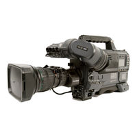
Panasonic AJ-SDX900E Service Manual (421 pages)
Camera/VTR, SDI Output/Pre-recording Board
Brand:
Panasonic
| Category:
Camcorder
| Size: 31.79 MB
Table of Contents
English
10
Safety Precautions
6
Table of Contents
10
1 Servicing Fixtures & Tools
11
2 Alignment Tape
14
VFM3580KM (NTSC) (25M Adjustment Tape)
14
VFM3680KM (PAL) (25M Adjustment Tape)
14
Vfm3582Km (Ntsc)/Vfm3682Km (Pal)
14
(Manufacturer (X-Value) Adjustment Tape)
14
3 List of Recommended Measuring and Instruments
15
4 Maintenance Schedule
16
5 Layout of the Maintenance Parts & Sensors
17
6 Emergency Eject
18
7 Cleaning Method
19
Cylinder Head Cleaning Method: (Daily)
19
Cylinder Lead Cleaning Method: (Weekly)
19
A/C Head Cleaning Method: (Weekly)
19
Pinch Roller and Capstan Shaft Cleaning Method: (Weekly)
19
Post Cleaning Method: (Weekly)
19
8 Basic Setting Menu Operations
20
Service Menu Operation
20
Factory Menu Operation
21
9 DIAG-MENU Display
22
Version Display Operation for CAMERA Software
22
Version Display Operation for VTR Software and Hour Meter Display
22
How to Reset Hour Meter
23
10 Error Rate Display and Confirmation Method
24
Error Rate Display Method
24
11 Software Version Upgrade Method
25
12 White Blemish Compensation
34
Preparation
34
Connection
34
Blemish Compensation Flow
34
Blemish Compensation Procedures
35
Remarks
38
13 Circuit Board Layout
39
Mechanical Adjustment
40
Mechanical Adjustment Procedures
42
Post Height Pre-Adjustment
42
Tension Adjustment Flowchart
42
Tension Arm Offset Adjustment
42
Tension Arm Neutral Position Adjustment
43
Tension Arm PLAY Voltage Adjustment and REV Voltage Confirmation
44
Tension Regulator Spring Adjustment
44
REV Tension Confirmation
45
Tension Confirmation
46
Photo Sensor Voltage Adjustment
46
Tape Path Adjustment Procedure
47
Envelope Waveform Adjustment
48
Post Limit Confirmation (PLAY)
48
A/C Head Adjustment
49
A/C Head Tilt Adjustment
51
A/C Head Height Adjustment
51
A/C Head Tilt Confirmation
52
A/C Head Height Confirmation
52
A/C Head Azimuth and X-Value Adjustment (SD 25M)
53
A/C Head Azimuth and X-Value Adjustment (SD 50M)
54
A/C Head Azimuth and X-Value Adjustment (HD CAM)
55
Compensation Adjustment of X Value
56
REV Tape Path Confirmation and Adjustment (T4 Post Height Adjustment)
56
CTL Self Recording Levelconfirmation
57
Play Tape Path Limit Confirmation
58
Confirmation of Envelope on REV, REW and FF Mode
58
Confirmation of Play Start Envelope
59
REV Mode Tape Path Limit Confirmation
59
FF, REW Mode Tape Path Limit Confirmation
60
Screw Lock Tight of A/C Head and T3, T4 Post
60
Confirmation of Tape Damage for Long Tape Playback (SD VTR Only)
60
LISTA Adjustment Procedure (SD 25M VTR)
61
LISTA Adjustment Procedure (SD 50M VTR)
62
LISTA Adjustment Procedure (SD 50M CAM)
63
LISTA Adjustment Procedure (HD CAM)
64
LISTA Connection and Boot up
65
How to Entry the Attachment Data of Alignment Tape
67
LISTA Sensitivity Adjustment and Sensitivity Detection
68
LISTA Linearity Adjustment and Waving Measurement
71
Self-REC/PLAY Envelope Waveform Confirmation
73
DV Playback Envelope Waveform Confirmation
74
(DV Playback Compatible Model Only)
74
Major Mechanical Parts Replacement & Adjustment Procedures
75
Cylinder Unit Replacement
75
Cleaning Arm Unit Replacement
76
T1 Guide Position Adjustment
76
Adjustment Flow Chart after Cylinder Unit Replacement
77
Supply & Take-Up Reel Rotor Unit Replacement (in Case of Studio VTR)
78
Supply & Take-Up Reel Rotor Unit Replacement (in Case of Camera Recorder)
79
Main Brake Torque Confirmation
80
Supply & Take-Up Brake Arm Unit Replacement (Studio VTR Only)
80
Supply Brake Solenoid Replacement and Adjustment (Studio VTR Only)
81
Take-Up Brake Solenoid Replacement and Adjustment (Studio VTR Only)
81
Pinch Solenoid Replacement
82
Pinch Solenoid Position Adjustment
82
Pinch Arm Unit Replacement
83
Loading Motor Replacement
83
Mode SW Unit Replacement
84
Main Cam Gear Replacement
84
Thrust Screw Replacement and Adjustment
85
S5 Post Base Unit Replacement
85
Tension Arm Unit Replacement
86
S1 Post Loading Arm Unit Replacement & Adjustment
87
T1 Boat Unit Replacement and Adjustment
88
T1 Loading Arm Unit Replacement & Adjustment
90
M-Cassette Brake Base Unit Replacement (Camera Recorder Only)
90
A/C Head Replacement & Adjustment
91
Cleaner Solenoid Replacement & Adjustment
93
Distinction SW Unit Replacement (Studio VTR Only)
94
MIC Sensor SW Unit Replacement (Camera Recorder Only)
95
Reel Drive Motor Unit Replacement (Studio VTR Only)
95
L-M Release Angle Unit Replacement (Studio VTR Only)
95
Slide Rod Unit Replacement & Adjustment (Studio VTR Only)
96
M-Stopper Solenoid Replacement & Adjustment (Studio VTR Only)
97
T4 Post Position Adjustment
98
Compensation Adjustment of X Value
99
Name of Tape Transportation
100
Table of Test Point
101
Table of Test Point for each Adjustment Item
102
Tension Arm Offset Adjustment
102
Tension Arm Neutral Position Adjustment
102
Tension Arm PLAY and REV Voltage Adjustment and Confirmation
102
Tension Regulator Spring Adjustment
103
REV Tension Confirmation
103
Tension Confirmation
103
Photo Sensor Voltage Adjustment
104
Envelope Waveform Adjustment
104
A/C Head Height Adjustment
104
A/C Head Tilt Adjustment
104
A/C Head Tilt Confirmation
104
A/C Head Height Confirmation
104
A/C Head Azimuth and X-Value Adjustment (SD 50M)
105
REV Tape Path Confirmation and Adjustment (T4 Post Height Adjustment)
105
CTL Self Recording Level Confirmation
106
Confirmation of Envelope on REV, REW and FF Mode
106
Confirmation of Play Start Envelope
106
REV Mode Tape Path Limit Confirmation
106
LISTA Connection and Boot up
106
LISTA Sensitivity Adjustment and Sensitivity Detection
107
LISTA Linearity Adjustment and Waving Measurement
108
Self-REC/PLAY Envelope Waveform Confirmation
108
Table of Connector
109
Cylinder Unit Replacement
109
T1 Guide Position Adjustment
109
Supply & Take-Up Reel Rotor Unit Replacement (in Case of Camera Recorder)
109
Main Brake Torque Confirmation
109
Pinch Solenoid Replacement
109
Loading Motor Replacement
109
Mode SW Unit Replacement
109
A/C Head Replacement & Adjustment
110
Cleaner Solenoid Replacement & Adjustment
110
MIC Sensor SW Unit Replacement (Camera Recorder Only)
110
Connector Location
111
SERVO P.C.board
111
Electrical Adjustment
112
Introduction of Electrical Adjustment
114
Adjustment after Replacement of Major Part (Circuit Board)
114
Contexture of Electrical Adjustment
115
Camera Section
115
Vtr Section
115
Audio Section
115
Preparations for Adjustment
116
Menu Setting
116
Instruction of Adjustment Software (EVR)
117
Adjustmrnts for Camera Section
118
Int. 27Mhz Adj
118
VF out Level Adj
118
Monitor out Level Adj
119
Video out Level Adj
119
Y out Level Adj
120
PB / PR out Level Adj
120
Color Framing Adj
120
Pulse Cancel Adj
121
Test Signal Level Adj
121
AD Level Fine Adj
122
Pre Knee Point Adj
122
Pedestal Adj
122
Pedestal Adj. (P Mode)
123
Pedestal Tracking VR Adj
123
Standard Sensitivity Adj
123
Standard Sensitivity Adj. (P Mode)
124
Sub Voltage Adj
124
Sub Voltage Adj. (P Mode)
124
Standard Sensitivity Fine Adj
125
Standard Sensitivity Fine Adj. (P Mode)
125
Pre Clip Voltage Adj
125
Pre Clip Voltage Adj. (P Mode)
126
Pre Clip Carrier Adj. (P Mode)
126
ATW Parameter Adj
127
Modulation Ratio Adj
127
White Shading Offset Adj. (0 Db)
127
White Shading Offset Adj. (+18 Db)
128
White Shading Offset Adj. (+18 / +12 Db)
128
White Shading Adj. (Standard)
128
White Shading Adj. (Extension Lens)
129
White Shading Adj. (Converter Lens)
129
Black Shading Adj
129
Flare Adj
130
Gamma Adj. (0 Db)
130
Gamma Adj. (0 Db, P Mode)
131
Gamma Adj. (+21 Db)
131
Gamma Adj. (+21 Db, P Mode)
131
Adjustmrnts for Mech/Servo Section
132
T Reel Torque Offset Adj
132
S Reel Torque Offset Adj
132
Tension Offset Voltage Adj
132
Tape Beginning Detection Sensitivity Adj
132
Tape End Detection Sensitivity Adj
132
PG Shifter (1) Adj
133
PG Shifter (2) Adj
133
ATF Envelope Level Adj
133
Adjustmrnts for Rf Section
134
RF Envelope Level Adj
134
Playback Error Rate Confirmation
134
Flying Erase Confirmation
134
Recording Current Setting
135
RP Error Rate Confirmation
135
Head Clogging Detection Level Adj. L-Ch
135
Head Clogging Detection Level Adj. R-Ch
136
Head Clogging Detection Level Confirmation
136
Adjustmrnts for Audio Section
137
PB Level Adj
137
Recording Level (1) Adj
137
Recording Level (2) Adj
137
CUE Playback Level Adj
138
CUE Recording Current Adj
138
Tp and Vr Location
139
Unknown
143
Block Diagrams
143
System Block Diagram (Overall)
144
Pulse/ Drive/ CCD Block Diagrams
145
Pre Amp (Dds) Block Diagram
146
Pre Process Block Diagram
147
Camera Dsp Block Diagram
148
Vtr Codec Block Diagram
149
Ecc Sys Block Diagram
150
Servo Block Diagram
152
Audio Lcd Block Diagram
153
Vtr Power/ Camera Power Block Diagrams
154
Schematic Diagrams
156
Overall (1/1)
160
Mother
161
Mother (1/2)
162
Mother (2/2)
162
Drive
163
Drive (1/1)
163
Pulse (1/2)
164
Pulse (2/2)
164
CCD
166
CCD (1/1)
166
Pre Amp
167
Pre Amp (1/4)
168
Pre Amp (2/4)
169
Pre Amp (3/4)
170
Pre Amp (4/4)
170
Pre Process
171
Pre Process (1/4)
171
Pre Process (2/4)
172
Pre Process (3/4)
173
Pre Process (4/4)
174
Cam Dsp
176
Cam Dsp (Genlock1) (3/16)
177
Cam Dsp (Genlock2) (4/16)
177
Cam Dsp (Camsys1) (5/16)
179
Cam Dsp (Shading) (8/16)
182
Cam Dsp (Adc1) (9/16)
182
Cam Dsp (Vfp-Memory) (11/16)
185
CAM DSP (LSI-5Th) (12/16)
186
Cam Dsp (If-Lsi) (13/16)
187
Cam Dsp (Char-Fpga) (14/16)
188
Cam Dsp (Char-Fpga) (15/16)
188
Cam Dsp (Out-Da) (16/16)
190
Codec (Connector) (1/9)
191
Codec (Power) (2/9)
191
Codec (Clk Distribution) (3/9)
193
Codec (I/O Buffer) (4/9)
194
Codec (Fpga<Preprocess>) (5/9)
195
Codec (Comp100) (6/9)
196
Codec (Prep50) (7/9)
196
Codec (Shuf Mem) (8/9)
198
Codec (411 Fliter) (9/9)
199
Ecc Sys (M32) (6/8)
206
Ecc Sys (Tc IC) (7/8)
207
Ecc Sys (Connector) (8/8)
207
RFEQ (a Ch) (1/13)
208
RFEQ (B Ch) (2/13)
209
RFEQ (C Ch) (3/13)
210
RFEQ (D Ch) (4/13)
211
Rfeq (Pb) (5/13)
212
Rfeq (Evr) (6/13)
213
Rfeq (Logic) (7/13)
214
Rfeq (Fe1) (8/13)
214
Rfeq (Envdet) (9/13)
216
Rfeq (Power) (10/13)
217
Rfeq (Connector) (12/13)
219
Rfeq (Connector) (13/13)
220
H-Buff (Fe) (1/7)
221
H-BUFF (a Ch) (2/7)
222
H-BUFF (B Ch) (3/7)
223
H-BUFF (C Ch) (4/7)
224
H-BUFF (D Ch) (5/7)
225
H-Buff (Tp, Vr) (6/7)
226
H-Buff (Connector) (7/7)
227
SERVO (SERVO Ucom) (1/10)
234
Servo (Meca Sw/Loading Drive) (7/10)
234
Servo (Servo Power, I/F) (9/10)
236
Servo (Ctl Amp) (10/10)
237
Audio Lcd
238
Audio Lcd (Input) (1/14)
250
Audio Lcd (Agc/Lim12) (4/14)
251
Audio Lcd (Connect) (14/14)
251
Cue (1/3)
254
Cue (2/3)
254
Cue (3/3)
255
Vtr Power (Card) (5/7)
261
Vtr Power (Card Sel) (6/7)
262
Vtr Power (7/7)
263
Cam Power
264
Cam Power (3/5)
265
Cam Power (5/5)
266
Front Sw
269
Interface (1/1)
270
Menu Sw
271
Rear Jack
272
Sd Sdi Tx (1/3)
273
Sd Sdi Tx (2/3)
274
Sd Sdi Tx (3/3)
275
Pre-Rec (Connector) (1/2)
276
Pre-Rec (Memory) (2/2)
277
Rfeq P.C.board (Vep85211A)
291
CCD P.C.board (Vep20981A)
302
H-Buff P.C.board (Vep85210A)
304
Rear Audio P.C.board (Vep84386A)
305
Cue P.C.board (Vep84388A)
306
Interface P.C.board (Vep80C51A)
307
Rear Jack P.C.board (Vep80C52A)
308
Front Sw P.C.board (Vep80C57A)
308
L Side P.C.board (Vep80C53A)
309
Front MIC P.C.board (Vep80C54A)
309
Hp P.C.board (Vep80C64A)
309
Menu Sw P.C.board (Vep80C58A)
310
Sd Sdi P.C.board (Vep83607A):Aj-Ya902G
311
Pre Rec P.C.board (Vep83608A):Aj-Ya903G
312
Exploded Views
313
Replacement Parts List
313
Servicing Fixtures & Tools
314
Casing & Frame Assembly
315
Overall Section
317
Acassette Cover Assembly
318
Bside Case (L) Assembly
318
C L Side Section
319
Dside Case (R) Section
319
Eside Case (R) 1 Assembly
321
Ffront Case Section
322
Gfront Case 1 Assembly
322
Hcamera Assembly
323
Jbottom Case Section
324
Kshoulder Pad Assembly
325
Ltop Case Section
325
M ] Handle Section
326
Nhandle Cover Section
326
Rback Case Section
328
Mechanical Chassis Assembly (1)
330
Mechanical Chassis Assembly (2)
332
Mechanical Chassis Assembly (3)
334
Packing Parts Assembly
337
Electrical Replacement Parts List (Aj-Sdx900P)
338
Electrical Replacement Parts List (Aj-Sdx900E/ D908Mc)
378
Packing Parts Assembly (Aj-Ya902G)
418
Packing Parts Assembly (Aj-Ya903G)
419
Electrical Replacement Parts List (Aj-Ya902G)
420
Electrical Replacement Parts List (Aj-Ya903G)
421
Advertisement
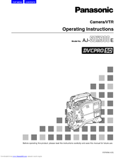
Panasonic AJ-SDX900E Operating Instructions Manual (102 pages)
Camera/VTR DCVPRO 50
Brand:
Panasonic
| Category:
Camcorder
| Size: 2.36 MB
Table of Contents
Table of Contents
4
Operating Instructions
1
Chapter 1 General
6
Features of the Camera Unit
6
Features of the VTR Unit
7
System Configuration
8
Chapter 2 Parts and Their Functions
9
Audio Function Section
10
Shooting and Recording/Playback Function Section
12
Menu Operation Section
14
Time Code Related Section
15
Display Window and Its Displays
16
Viewfinder Section
18
Chapter 3 Recording and Playback
19
Cassette Tapes
19
Basic Procedures
20
News Rec Function
22
When Aj-Ya903G Is Not Installed
22
Scene-To-Scene Continuity
22
Interval Rec Function
23
And When It Is Not Installed
23
When Aj-Ya903G Is Installed
23
Pre-Recording Function
23
Normal Playback and
25
Playback at Different Speeds
25
Chapter 4 Adjustments and Settings for Recording
26
Rec Review Function
25
RETAKE Function
25
Adjusting the White Balance
26
Adjusting the Black Balance
28
Setting the Electronic Shutter
29
Shutter Modes
29
Selecting the Recording System
30
Setting the Synchro Scan Mode
30
Selecting the Recording Signals
30
Adjusting the Audio Signal Recording Levels
31
Selecting the Audio Input Signals and Adjusting Their Recording Levels
31
CH3 and CH4 Recording Levels
32
Setting the Time Data
32
Setting the User's Bit
32
Setting the Internal Clock's Date and Time
33
Setting the Time Code
34
Setting the UMID Information
35
Menu Displays on the Viewfinder Screen
36
Basic Menu Operations
36
Selecting the User Menus
37
Viewfinder Screen Status Displays
38
Viewfinder Lamp Displays
38
Display Modes and Setting Changes/Adjustment Result Messages
44
Setting the Camera ID
44
Setting the Marker Displays
44
Checking the Return Video Signal on the Viewfinder
45
Marker Check Screen Displays
45
Marker Select Button Function
45
Mode Check Button Function
45
Mode Check Screen Displays
45
Menu-Driven Function Setup
46
Allocating Functions to the USER MAIN USER1 and USER2 Buttons
47
Setting the Color Temperature Manually
48
Data Handling
48
Setup Card Operations
49
How to Use the User Data
52
How to Use the Scene File Data
53
How to Return the Menus Settings to the User Standard Settings
56
Chapter 5 Preparation
57
Supplying the Power
57
Using an AC Power Supply
60
The Flange Back and White Shading Adjustments
61
Audio Input Signal Preparations
65
When Using an Audio Component
66
Mounting the Unit on a Tripod
67
Attaching the Rain Cover
68
Chapter 6 Maintenance and Inspections
69
Inspecting the VTR Unit
70
Self-Diagnosis Function
71
Maintenance
72
Cleaning Inside the Viewfinder
72
Head Cleaning
72
Connectors and Signals
73
Warning Description Tables
74
Warning System
74
Emergency Eject
76
Error Codes
76
Option Mode
78
System Mode
78
System Setting
78
Output Sel
79
Rec Function
79
Paint
80
Color Correction
81
Low Setting
81
High Setting
82
MID Setting
82
Skin Tone Dtl
83
Knee/Level
84
Camera Setting
85
Vf Marker
86
Mode Check Ind
87
Vf Indicator2
87
Chapter 7 Menu Description Tables
77
Operation
88
Camera ID
88
Shutter Select
88
Shutter Speed
88
Sw Mode
89
User Sw
89
User Sw Gain
90
White Balance Mode
90
Card R/W Select
91
Card Read/Write
91
Iris
91
Lens Adj
92
Lens File
92
System Check
92
Black Shading
93
Vtr Menu
93
Vtr Function
93
White Shading
93
AUTO: the Voltage Is Set Automatically
94
Bp-L60/90
94
End
94
For Enabling or Disabling the Selection Made
94
For the BATTERY SELECT Item
94
Is to be Set
94
MANUAL: the Voltage Is Set Manually
94
Near End
94
The Selection Is Disabled
94
The Selection Is Enabled
94
Auto Manual
95
Menu Description Tables
96
Battery Setting2
96
Charge Is to be Considered Nearly Depleted
96
End
97
For Enabling or Disabling the Selection Made
97
For Selecting in 0.1 V Steps the Voltage at
97
For the BATTERY SELECT Item
97
MIC/Audio1
97
Near End
97
Nearly Depleted
97
The Selection Is Disabled
97
The Selection Is Enabled
97
Which the Battery Charge Is to be Considered
97
MIC/Audio2
98
Option Menu
99
Vtr Diag
99
Umid Set/Info
99
Chapter 8 Specifications
100
Advertisement
Related Products
Panasonic AJSDX900P - 24P DVCPRO 50
Panasonic AJSDX900 - 24P DVCPRO 50
Panasonic AJ-SD255PE
Panasonic AJ-SDC905
Panasonic AJ-SDC905p
Panasonic AJ-SD945E
Panasonic AJ-SD965E
Panasonic DVCPRO AJ-SDC615E
Panasonic DVCPRO AJ-SDC615P
Panasonic AJ-SDC905E
Panasonic Categories
Camcorder
Air Conditioner
TV
Digital Camera
Cordless Telephone
More Panasonic Manuals
Login
Sign In
OR
Sign in with Facebook
Sign in with Google
Upload manual
Upload from disk
Upload from URL