Sign In
Upload
Manuals
Brands
OMRON Manuals
Control Unit
SYSMAC C200HS
OMRON SYSMAC C200HS Manuals
Manuals and User Guides for OMRON SYSMAC C200HS. We have
7
OMRON SYSMAC C200HS manuals available for free PDF download: Operation Manual, Installation Manual, Specification
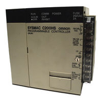
Omron SYSMAC C200HS Operation Manual (503 pages)
Programmable Controllers
Brand:
Omron
| Category:
Controller
| Size: 3.58 MB
Table of Contents
Table of Contents
7
Introduction
9
General Precautions
11
Intended Audience
11
Operating Environment Precautions
11
Safety Precautions
11
Application Precautions
12
Conformance to EC Directives
13
Section 1 Introduction
14
Overview
15
PC Terminology
15
The Origins of PC Logic
15
OMRON Product Terminology
16
PC Terminology
16
Overview of PC Operation
17
Peripheral Devices
17
Available Manuals
18
Peripheral Devices
18
Introduction . . . . . . . . . . . . . . . . . . . . . . . . . . . . . . . . . . . .
19
New C200HS Features
19
Faster Execution Times
20
Improved Memory Capabilities
20
Larger Instruction Set
21
Improved Interrupt Functions
22
SYSMAC NET Link and SYSMAC LINK Capabilities
22
Built-In RS-232C Connector
23
Debugging and Maintenance
23
More Flexible PC Settings
23
New Programming Console Operations
23
Peripheral Devices
23
Using C200H Programs
24
Section 1
19
Section 2 Hardware Considerations
27
CPU Components
28
CPU Indicators
29
Peripheral Device Connection
30
PC Configuration
30
CPU Capabilities
31
Memory Cassettes
32
Installing Memory Cassettes
33
CPU DIP Switch
35
Section 3 Memory Areas
36
Data Area Structure
38
Hardware Considerations . . . . . . . . . . . . . . . . . . . . . . . . .
42
Memory Areas . . . . . . . . . . . . . . . . . . . . . . . . . . . . . . . . . .
42
IR (Internal Relay) Area
42
SR (Special Relay) Area
44
SYSMAC NET/SYSMAC LINK System
48
Link System Flags and Control Bits
50
Forced Status Hold Bit
52
FAL (Failure Alarm) Area
53
I/O Status Hold Bit
53
Low Battery Flag
53
Output off Bit
53
Clock Pulse Bits
54
Cycle Time Error Flag
54
First Cycle Flag
54
I/O Verification Error Flag
54
Arithmetic Flags
55
Group-2 Error Flag
55
Instruction Execution Error Flag, er
55
Special Unit Error Flag
55
Step Flag
55
Interrupt Subroutine Areas
56
RS-232C Port Communications Areas
56
Memory Cassette Areas
57
Peripheral Port Communications Areas
57
Data Save Flags
58
Data Transfer Error Bits
58
Ladder Diagram Memory Areas
58
Memory Error Flags
58
PC Setup Error Flags
58
Transfer Error Flags
58
AR (Auxiliary Relay) Area
59
Group-2 Error Flags
61
Optical I/O Unit and I/O Terminal Error Flags
61
Restarting Special I/O Units
61
Slave Rack Error Flags
61
Error History Bits
62
SYSMAC LINK System Data Link Settings
62
Active Node Flags
63
SYSMAC LINK/SYSMAC NET Link System Service Time
63
TERMINAL Mode Key Bits
64
CPU-Mounting Device Mounted Flag
65
Cycle Time Flag
65
Cycle Time Indicators
65
Data Tracing Flags and Control Bits
65
FPD Trigger Bit
65
Link Unit Mounted Flags
65
Power off Counter
65
DM (Data Memory) Area
66
Expansion DM Area
67
Special I/O Unit Data
67
Error History Area
68
PC Setup
69
HR (Holding Relay) Area
71
TC (Timer/Counter) Area
71
LR (Link Relay) Area
72
TR (Temporary Relay) Area
72
UM Area
72
Section 2
42
Section 3
42
Section 4 Writing and Inputting the Program
73
Basic Procedure
74
Instruction Terminology
74
Basic Ladder Diagrams
75
Basic Terms
76
Mnemonic Code
76
Ladder Instructions
77
OUTPUT and OUTPUT NOT
80
The END Instruction
80
Logic Block Instructions
81
Coding Multiple Right-Hand Instructions
88
Program Capacity
75
The Programming Console
88
The Keyboard
88
PC Modes
90
The Display Message Switch
90
Preparation for Operation
90
Entering the Password
91
Buzzer
91
Clearing Memory
92
Registering the I/O Table
94
Clearing Error Messages
95
Verifying the I/O Table
96
Reading the I/O Table
97
Clearing the I/O Table
99
SYSMAC NET Link Table Transfer (CPU31/33-E Only)
100
Inputting, Modifying, and Checking the Program
102
Setting and Reading from Program Memory Address
102
Entering and Editing Programs
103
Checking the Program
106
Displaying the Cycle Time
108
Program Searches
109
Inserting and Deleting Instructions
110
Jumps
117
Controlling Bit Status
118
DIFFERENTIATE up and DIFFERENTIATE down
119
Keep
119
Self-Maintaining Bits (Seal)
119
Work Bits (Internal Relays)
120
Programming Precautions
122
Program Execution
124
Section 5 Instruction Set
125
Instruction Set
125
Data Areas, Definer Values, and Flags
128
Instruction Format
128
Notation
128
Differentiated Instructions
129
Expansion Instructions
130
Coding Right-Hand Instructions
132
Instruction Set Lists
135
Alphabetic List by Mnemonic
135
Function Codes
135
Ladder Diagram Instructions
139
LOAD, LOAD NOT, AND, and NOT, OR, and or NOT
139
AND LOAD and or LOAD
140
Bit Control Instructions
140
OUTPUT and OUTPUT NOT - out and out NOT
140
DIFFERENTIATE up and down - DIFU(13) and DIFD(14)
141
Keep - Keep(11)
143
SET and RESET - SET and RSET
143
INTERLOCK and INTERLOCK CLEAR - IL(02) and ILC(03)
145
JUMP and JUMP END - JMP(04) and JME(05)
147
End - End(01)
148
No Operation - Nop(00)
148
Timer and Counter Instructions
148
Timer - Tim
149
High-Speed Timer - Timh(15)
153
Totalizing Timer - Ttim(87)
154
Counter - Cnt
155
Data Shifting
160
Shift Register - Sft(10)
160
Reversible Shift Register - Sftr(84)
162
Arithmetic Shift Left - Asl(25)
164
Arithmetic Shift Right - Asr(26)
164
Rotate Left - Rol(27)
165
Rotate Right - Ror(28)
165
One Digit Shift Left - Sld(74)
166
One Digit Shift Right - Srd(75)
166
Asynchronous Shift Register - Asft(17)
167
Word Shift - Wsft(16)
167
Data Movement
168
Move - Mov(21)
169
Move Not - Mvn(22)
169
Block Set - Bset(71)
170
Data Exchange - Xchg(73)
172
Single Word Distribute - Dist(80)
172
Data Collect - Coll(81)
174
Move Bit - Movb(82)
176
Transfer Bits - Xfrb(62)
178
Data Comparison
179
Compare - Cmp(20)
180
Double Compare - Cmpl(60)
182
Block Compare - Bcmp(68)
184
Area Range Compare - Zcp(88)
186
Double Area Range Compare - Zcpl
187
Signed Binary Compare - Cps
188
Double Signed Binary Compare - Cpsl
189
Data Conversion
190
Bcd-To-Binary - bin(23)
190
Binary-To-Bcd - Bcd(24)
191
Data Conversion
191
Double Bcd-To-Double Binary - Binl(58)
191
Double Binary-To-Double Bcd - Bcdl(59)
192
Hours-To-Seconds - Sec(65)
193
Seconds-To-Hours - Hms(66)
194
4-To-16 Decoder - Mlpx(76)
195
16-To-4 Encoder - Dmpx(77)
198
7-Segment Decoder - Sdec(78)
201
Ascii Convert - Asc(86)
204
Ascii-To-Hexadecimal - Hex
205
Scaling - Scl
208
Column to Line - Line(63)
210
Line to Column - Colm(64)
211
BCD Calculations
214
Decrement - Dec(39)
214
Increment - Inc(38)
214
Bcd Add - Add(30)
215
BCD Calculations
215
Clear Carry - Clc(41)
215
Set Carry - Stc(40)
215
Double Bcd Add - Addl(54)
216
Bcd Subtract - Sub(31)
217
Double Bcd Subtract - Subl(55)
219
Bcd Multiply - Mul(32)
221
Bcd Divide - DIV(33)
222
Double Bcd Multiply - Mull(56)
222
Double Bcd Divide - Divl(57)
223
Floating Point Divide - Fdiv(79)
224
Square Root - Root(72)
227
Binary Calculations
229
Binary Add - Adb(50)
229
Binary Calculations
230
Binary Subtract - Sbb(51)
231
Binary Divide - Dvb(53)
234
Binary Multiply - Mlb(52)
234
Double Binary Subtract - Sbbl
237
Signed Binary Multiply - Mbs
239
Double Signed Binary Multiply - Mbsl
240
Signed Binary Divide - Dbs
241
Double Signed Binary Divide - Dbsl
242
Special Math Instructions
243
Find Maximum - Max
243
Find Minimum - Min
244
Special Math Instructions
244
Average Value - Avg
245
Sum - Sum
247
Arithmetic Process - Apr(69)
249
Logic Instructions
259
Complement - Com(29)
259
Logic Instructions
260
Exclusive or - Xorw(36)
262
Subroutines and Interrupt Control
264
Interrupts
264
Subroutine Enter - Sbs(91)
267
SUBROUTINE DEFINE and RETURN - SBN(92)/RET(93)
269
Macro - Mcro(99)
270
Interrupt Control - Int(89)
272
Step Instructions
276
STEP DEFINE and STEP START-STEP(08)/SNXT(09)
276
Step Instructions
277
Special Instructions
285
Severe Failure Alarm - Fals(07)
285
Cycle Time - Scan(18)
286
Special Instructions
286
Trace Memory Sampling - Trsm(45)
287
Message Display - Msg(46)
288
Long Message - Lmsg(47)
289
Terminal Mode - Term(48)
290
I/O Refresh - Iorf(97)
291
Watchdog Timer Refresh - Wdt(94)
291
Group-2 High-Density I/O Refresh - Mprf(61)
292
Bit Counter - Bcnt(67)
293
Frame Checksum - Fcs
293
Failure Point Detection - Fpd
295
Data Search - Srch
299
Expansion DM Read - Xdmr
300
Network Instructions
301
Network Send - Send(90)
301
Network Instructions
302
About Network Communications
305
Serial Communications Instructions
307
Receive - Rxd
307
Serial Communications Instructions
308
Advanced I/O Instructions
312
Digital Switch Input - Dsw
314
Hexadecimal Key Input - Hky
318
Ten Key Input - Tky
321
Section 6 Program Execution Timing
326
Cycle Time
327
Cycle Time
328
Calculating Cycle Time
331
PC with I/O Units Only
331
PC with Link Units
332
Calculating Cycle Time
332
Instruction Execution Times
333
Instruction Execution Times
334
I/O Response Time
342
Basic Systems
342
Remote I/O Systems
343
I/O Response Time
343
One-To-One Link I/O Response Time
348
Interrupt Response Times
350
SECTION 7 Program Monitoring and Execution
353
Monitoring Operation and Modifying Data
356
SECTION 8 Communications
383
Parameters for Host Link and RS-232C Communications
384
SECTION 9 Memory Cassette Operations
392
Memory Cassettes
396
Troubleshooting
397
Alarm Indicators
398
Error Messages
402
Error Flags
403
Host Link Errors
405
SECTION 11 Host Link Commands
406
Communications Procedure
407
Command and Response Formats
409
Host Link Commands
417
Host Link Errors
436
A Standard Models
437
B Programming Instructions
446
C Error and Arithmetic Flag Operation
452
D Memory Areas
456
F Word Assignment Recording Sheets
467
G Program Coding Sheet
472
H Data Conversion Tables
474
I Extended ASCII
476
Glossary
487
Index
493
Revision History
499
Advertisement
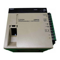
Omron SYSMAC C200HS Installation Manual (230 pages)
Brand:
Omron
| Category:
Controller
| Size: 2.36 MB
Table of Contents
Table of Contents
7
Precautions
11
General Precautions
12
Intended Audience
12
Operating Environment Precautions
12
Safety Precautions
12
Application Precautions
13
Conformance to EC Directives
14
Section 1 Introduction
15
Introduction
15
What Is a Control System
16
The Role of the PC
18
Input Devices
18
Output Devices
18
How Does a PC Work
19
New C200HS Features
22
Improved Memory Capabilities
22
Faster Execution Times
23
Larger Instruction Set
23
Expanded Number of I/O Points
23
Wide Selection of Special I/O Units
23
Improved Interrupt Functions
23
SYSMAC NET Link and SYSMAC LINK Capabilities
24
Built-In RS-232C Connector
24
More Flexible PC Settings
24
Debugging and Maintenance
24
Peripheral Devices
24
Comparisons between C200HS and C200H
25
Compatibility of C200HS and C200H Devices
27
Section 2 System Configuration and Unit Description
29
System Configuration and Unit Description
29
System Configuration
30
CPU Racks
30
Expansion I/O Racks
31
Slave Racks
31
Cpus
32
CPU Components
32
CPU Indicators
33
Power Supply
34
DIP Switch
36
Peripheral Device Connector
36
Operation Modes
37
Memory Cassettes
37
Expansion I/O Racks
38
Power Supply Unit
39
I/O Units
40
Standard I/O Units
41
Group-2 High-Density I/O Units
42
High-Density I/O Units Classified as Special I/O Units
44
Section 3 Installation
47
Installation
47
Installation Environment
48
Mounting Units to the Backplane
49
Installing Racks
53
I/O Connecting Cable
54
Mounting Requirements
55
Installing Memory Cassettes
57
Section 4 Wiring
59
Wiring
59
Power Supply Wiring
60
AC Power Supply
60
DC Power Supply
61
RUN Output Terminals
62
Grounding
62
Backplane Insulation Plate
63
Standard I/O Unit Wiring
64
Input Circuits
67
Output Circuits
68
External Wiring
71
System Design and Safety Considerations
71
Power Supply System and Emergency Stop Circuit
71
Interlock Circuit
72
Programmable Controller Power Interruptions
73
Section 5 Peripheral Devices and System Expansion
75
Peripheral Devices and System Expansion
75
Programming Console
76
Nomenclature
77
Checking Initial C200HS Operation
78
Expanding the System
78
Special I/O Units
81
Required Mounting Conditions
81
Special I/O Units and Functions
81
Ladder Support Software (LSS)
87
SYSMAC Support Software (SSS)
87
Section 6 Troubleshooting
89
Alarm Indicators
90
Programmed Alarms and Error Messages
90
Reading and Clearing Errors and Messages
90
Error Messages
91
CPU Racks and Expansion I/O Racks
95
Input Units
96
Output Units
97
Section 7 Inspection and Maintenance
99
Inspection and Maintenance
99
CPU and Power Supply Fuses
100
Output Unit Fuses
100
Output Unit Relays
101
Batteries
104
A Standard Models
107
B Specifications
117
Glossary
219
Index
223
Revision History
227
Omron SYSMAC C200HS Installation Manual (213 pages)
Brand:
Omron
| Category:
Controller
| Size: 4.87 MB
Advertisement
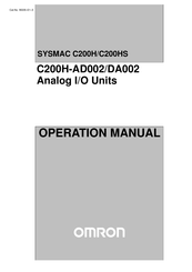
Omron SYSMAC C200HS Operation Manual (72 pages)
Analog I/O Units
Brand:
Omron
| Category:
I/O Systems
| Size: 0.34 MB
Table of Contents
Table of Contents
7
Precautions
11
General Precautions
12
Intended Audience
12
Safety Precautions
12
Application Precautions
13
Operating Environment Precautions
13
Section 1 System Design
15
System Design
15
Introduction
16
Safety Precautions
16
Basic Configuration
17
Example Configurations
18
System Considerations
19
Section 2 C200H-Ad002 Analog Input Unit
21
C200H-AD002 Analog Input Unit
21
Before Operation
22
Nomenclature and Functions
22
Switch Settings
23
Wiring
23
Bit and DM Area Allocations
28
Conversion Prohibit Settings
33
Functions and Programming
33
Input Signal Range Setting
34
Conversion Data Type Setting
35
Square Root Function
36
Scaling Function
37
Mean Value Function
39
Limit Warning Function
40
Peak Value Function
40
Input Disconnection Detection Function
42
Data Setting and Programming Examples
44
Data Settings
44
Programming
45
Troubleshooting
46
Section 3 C200H-Da002 Analog Output Units
49
C200H-DA002 Analog Output Units
49
Before Operation
50
Nomenclature and Functions
50
Switch Settings
51
Wiring
52
Bit and DM Allocations
55
Programming
56
Troubleshooting
56
A Standard Models
59
B Specifications
61
C Data Memory Coding Sheet
67
Index
71
Omron SYSMAC C200HS Installation Manual (26 pages)
Brand:
Omron
| Category:
Controller
| Size: 0.51 MB
Table of Contents
Table of Contents
10
Intended Audience
11
General Precautions
11
Safety Precautions
11
Operating Environment Precautions
11
Application Precautions
12
Conformance to EC Directives
13
What Is a Control System
15
The Role of the PC
17
Input Devices
17
Output Devices
17
How Does a PC Work
18
New C200HS Features
21
Improved Memory Capabilities
21
Faster Execution Times
22
Larger Instruction Set
22
Expanded Number of I/O Points
22
Wide Selection of Special I/O Units
22
Improved Interrupt Functions
22
SYSMAC NET Link and SYSMAC LINK Capabilities
23
Built-In RS-232C Connector
23
More Flexible PC Settings
23
Debugging and Maintenance
23
Peripheral Devices
23
Comparisons between C200HS and C200H
24
Compatibility of C200HS and C200H Devices
26
OMRON SYSMAC C200HS Specification (18 pages)
Motion Control Unit
Brand:
OMRON
| Category:
Control Unit
| Size: 0.16 MB
Table of Contents
Options (Sold Separately)
6
Auxiliary Codes
8
Control System
9
Connected Configuration
9
Exchanging Data
10
Component Names
11
External Connection Diagram
12
Connection Examples
16
OMRON SYSMAC C200HS Specification (17 pages)
Position Control Unit
Brand:
OMRON
| Category:
Control Unit
| Size: 0.19 MB
Table of Contents
Product Specifications
2
Position Control Unit
2
Options (Sold Separately)
6
System Configuration
8
Exchanging Data
9
External I/O Connectors
11
External Connection Diagram
12
Dimensions (Unit: MM)
15
Advertisement
Related Products
Omron C200HS-SNT32
OMRON C200HW-NC213 -
OMRON SYSMAC C200HE
OMRON SYSMAC C200HX
OMRON C200HW-SRM21
Omron SYSMAC C200H-NC112
Omron C200HW-SRM21-V1 CS1W-SRM21
Omron SYSMAC C200H-PID01
Omron SYSMAC C200H-PID03
Omron SYSMAC LINK C200HW-SLK23
OMRON Categories
Blood Pressure Monitor
Controller
Accessories
Switch
Inverter
More OMRON Manuals
Login
Sign In
OR
Sign in with Facebook
Sign in with Google
Upload manual
Upload from disk
Upload from URL