Sign In
Upload
Manuals
Brands
Omron Manuals
Accessories
NX-EIC202
Omron NX-EIC202 Manuals
Manuals and User Guides for Omron NX-EIC202. We have
4
Omron NX-EIC202 manuals available for free PDF download: User Manual, Connection Manual, Quick Start Manual
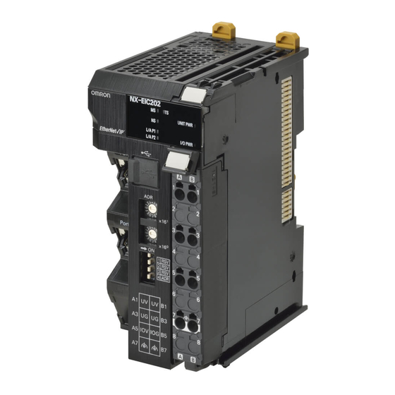
Omron NX-EIC202 User Manual (430 pages)
Machine Automation Controller NX-series EtherNet/IP Coupler Unit
Brand:
Omron
| Category:
Controller
| Size: 21.91 MB
Table of Contents
Introduction
3
Intended Audience
3
Applicable Products
3
Table of Contents
4
Contents
5
Relevant Manuals
10
Manual Structure
11
Page Structure and Icons
11
Special Information
12
Precaution on Terminology
12
Contents
13
Terms and Conditions Agreement
15
Warranty, Limitations of Liability
15
Application Considerations
16
Disclaimers
16
Safety Precautions
17
Definition of Precautionary Information
17
Symbols
17
Warnings
18
Cautions
19
Precautions for Safe Use
20
Precautions for Correct Use
25
Regulations and Standards
26
Conformance to EU Directives
26
Conformance to UL and CSA Standards
27
Conformance to Shipbuilding Standards
27
Conformance to KC Standards
27
Software Licenses and Copyrights
27
Unit Versions
28
Unit Versions and Support Software Versions
30
Related Manuals
31
Terminology
36
Revision History
38
Sections in this Manual
39
Ethernet/Ip Networks
41
Section 1 Ethernet/Ip Networks
42
Introduction to Ethernet/Ip
42
Ethernet/Ip Features
42
Ethernet/Ip Network Configuration Elements
45
System Configuration Example of an Ethernet/Ip Network
45
Introduction to Configuration Devices
46
Support Software Used to Construct a Network
47
Features of Ethernet/Ip Slave Terminals
52
System Configurations of Ethernet/Ip Slave Terminals
55
System Configuration
55
Types of NX Units
57
Safety Control System
58
Support Software
59
Applicable Support Software
59
Connection Method and Procedures
59
Specifications
62
General Specifications of Ethernet/Ip Slave Terminals
62
Ethernet/Ip Coupler Unit Specifications
63
End Cover Specifications
66
Procedures
67
Ethernet/Ip Slave Terminal Application Procedures
67
Details
69
Part Names and Functions
71
Parts and Names
72
Ethernet/Ip Coupler Units
72
NX Units
73
End Cover
74
Indicators
75
Hardware Switch Settings
78
Rotary Switches
78
DIP Switch
79
Communications Connector and Peripheral USB Port
80
Terminal Blocks
81
DIN Track Contact Plate
83
Designing the Power Supply System
85
Power Supply System and Design Concepts
86
Power Supply System and Types of Power Supplies
86
NX-Series Power Supply-Related Units
87
Design Concepts for Power Supply to the Ethernet/Ip Slave Terminal
89
Designing the NX Unit Power Supply System
90
Procedure for Designing the NX Unit Power Supply System
90
Calculation Example for the NX Unit Power Supply
91
Designing the I/O Power Supply System
93
I/O Power Supply Method
93
Designing the I/O Power Supply from the NX Bus
94
Designing the I/O Power Supply from External Sources
98
Restrictions on Inrush Current for ON/OFF Operation
98
Selecting External Power Supplies and Protective Devices
100
Selecting the Unit Power Supply
100
Selecting the I/O Power Supplies
102
Selecting Protective Devices
103
Section 6 Installation
108
Installation
108
Installing Units
108
Installation Precautions
108
Installation Orientation
109
Preparations for Installation
112
Installation Orientation
114
Installing the Ethernet/Ip Coupler Unit
115
Installing and Connecting NX Units
118
Mounting the End Cover
121
Mounting the End Plates
123
Attaching Markers
124
Removing Units
125
Assembled Appearance and Dimensions
127
Control Panel Installation
130
Temperature
130
Humidity
132
Vibration and Shock
132
Atmosphere
132
Electrical Environment
132
Grounding
137
Wiring
139
Section 7 Wiring
140
Ethernet/Ip Network Wiring
140
Installation Precautions
140
Preparations for Installation
140
Pin Arrangement of Communications Connectors on the Ethernet/Ip Coupler Unit
141
Connecting Communications Cables and Connectors
142
Connecting Communications Cables
142
Connecting the Power Supply and Ground Wires
144
Wiring the Ethernet/Ip Coupler Unit
144
Wiring the Power Supply to the Ethernet/Ip Slave Terminal
145
Grounding the Ethernet/Ip Slave Terminal
145
Precautions for Wiring the Ethernet/Ip Slave Terminal Together with Computers and Other Peripheral Devices
149
Wiring to the Screwless Clamping Terminal Block
149
Connecting USB Cable
164
Wiring External Signal Lines
166
Ethernet/Ip Communications
167
Section 8 Ethernet/Ip Communications
168
Ethernet/Ip Functions
168
Implicit Message Communications
168
Explicit Message Communications
169
Tag Data Links
170
Tag Data Link Data Areas
171
Creating Tag Data Links
173
Setting up Slave Terminals
175
Section 9 Setting up Slave Terminals
177
Settings and Setting Procedures
177
Items to Set
177
Slave Terminal Parameters
179
Setting Procedures
179
Setting Slave Terminal Parameters
181
Items to Set
181
Setting the NX Unit Configuration Information
181
I/O Allocation Information
185
I/O Allocation Information
186
Unit Operation Settings
196
Unit Application Data
197
Support Software Functions Used as Required
198
Transferring and Comparing Settings
202
Transferring Slave Terminal Setting Information through the USB Port on the Ethernet/Ip Coupler Unit
202
Comparing Settings
203
Setting IP Address
205
Directly Setting the IP Address with the Network Configurator
205
Getting the IP Address from the BOOTP Server with the Network Configurator
207
Directly Setting the IP Address Using Hardware Switches
208
Getting an IP Address from the BOOTP Server
209
Setting Tag Data Links
210
Starting the Network Configurator
210
Tag Data Link Setting Procedure
212
Registering Devices
213
Determine Tag Sizes
214
Creating Tags and Tag Sets
216
Connection Settings
230
Tag Data Parameters and Specifications
237
Downloading Tag Data Link Parameters
237
Uploading Tag Data Link Parameters
240
Starting and Stopping Tag Data Links
243
Additional Tag Data Link Functions
244
Assigning Network Variables
245
Basic I/O Mapping
245
Support Software I/O Allocation Functions
247
I/O Refreshing
249
Introduction to I/O Refreshing for Ethernet/Ip Slave Terminals
250
Communications Performance
253
I/O Response Time
253
Functions
259
NX Unit Mounting Settings
260
Introduction
260
Applications
261
Setting NX Units as Unmounted Units
262
Event Logs
264
Introduction
264
Detailed Information on Event Logs
265
Automatic Clock Adjustment
267
Reading Event Logs
268
Clearing Event Logs
270
Exporting the Event Log
271
Clearing All Memory
273
Introduction
273
Details on Clearing All Memory
273
Procedure for Clearing All Memory
274
Restarting
278
Introduction
278
Details on Restarting
278
Procedure for Restarting
279
Changing Event Levels
280
Introduction
280
Details on Changing Event Levels
280
Procedure to Change an Event Level
280
Fail-Soft Operation
282
Overview
282
Application
283
Details on Fail-Soft Operation
283
Monitoring Total Power-ON Time
285
Overview
285
Details on Monitoring Total Power-ON Times
285
Checking Total Power-ON Times
285
Ethernet Switch Functions
286
Troubleshooting
287
Section 12 Troubleshooting
288
How to Check for Errors
288
Checking for Errors and Troubleshooting with the Indicators
289
On the Ethernet/Ip Coupler Unit
289
Checking for Errors and Troubleshooting with Support Software
296
Checking Status with the Network Configurator
296
Checking for Errors and Troubleshooting with
296
Connection Status Codes and Troubleshooting
303
Checking for Errors from the Sysmac Studio
307
Checking for Errors from Support Software
307
Other than the Sysmac Studio
307
Event Codes for Errors and Troubleshooting Procedures
308
Resetting Errors
337
Procedure to Reset Errors
337
Troubleshooting Other Errors
340
Maintenance and Inspection
341
Section 13 Maintenance and Inspection
342
Cleaning and Maintenance
342
Cleaning
342
Periodic Inspections
342
Maintenance Procedures
344
Importing and Exporting Data
344
Replacement Procedure for the Ethernet/Ip Coupler Unit
344
Basic Replacement Procedure for NX Units
345
Appendices
347
Supported CIP Objects
349
A-1-1 Identity Object (Class ID: 01 Hex
349
Identity Object (Class ID: 01 Hex
349
Assembly Object (Class ID: 04 Hex
351
A-1-3 NX Configuration Object (Class ID: 74 Hex
352
A-1-4 TCP/IP Interface Object (Class ID: F5 Hex
368
Ethernet Link Object (Class ID: F6 Hex
371
A-1-6 Clear Error Explicit Message Example Using CMND(490
373
Response Codes
376
TCP/UDP Message Service
380
A-2-1 System Configuration for Using the TCP/UDP Message Service
380
System Configuration for Using the TCP/UDP Message Service
380
A-2-2 Setup Procedure for TCP/UDP Message Service
382
A-2-5 TCP/IP and UDP/IP Port Number Setting
382
A-2-3 Detailed Setup Procedure for TCP/UDP Message Service
383
TCP/UDP Message Service Specifications
384
A-2-5 TCP/IP and UDP/IP Port Number Setting
387
A-2-6 Troubleshooting Errors Related to the TCP/UDP Message Service
389
Examples of Ethernet/Ip Slave Terminal Settings and I/O Data Control Procedure Using Messages
391
A-3-1 Changing the Unit Operation Settings for the Ethernet/Ip Coupler Unit
392
A-3-2 Changing the Unit Operation Settings of One NX Unit
392
A-3-3 Changing the Unit Operation Settings of Multiple NX Units
393
A-3-4 Changing the Unit Operation Settings of the Entire Ethernet/Ip Slave Terminal
393
Changing the Unit Operation Settings of the Entire Ethernet/Ip Slave Terminal
393
A-3-5 Initializing the Unit Operation Settings of One NX Unit
395
A-3-6 Reading and Writing I/O Data for Ethernet/Ip Slave Terminals
395
Programming Example to Detect Valid I/O Data
397
Application Procedure for the Default Settings
398
A-5-1 Basic Procedure
398
Basic Procedure
398
Connecting to Masters from Other Manufacturers
400
A-6-1 System Configuration
400
System Configuration
400
A-6-2 Application Procedure
401
Dimensions
402
A-7-1 Ethernet/Ip Coupler Unit
402
Ethernet/Ip Coupler Unit
402
A-7-2 End Cover
403
End Cover
403
NX Objects
404
A-8-1 NX Objects
404
A-8-2 Format of Object Descriptions
404
Format of Object Descriptions
404
A-8-3 Unit Information Objects
405
A-8-4 Objects that Accept I/O Allocations
407
A-8-5 Other Objects
410
Other Objects
410
Terminal Block Model Numbers
411
A-9-1 Model Number Notation
411
Models
411
A-9-2 Models
411
Version Information
413
A-10-1 Relationship between Unit Versions
413
A-10-2 Functions that Were Added or Changed for each Unit Version
416
A-10-3 Unit Versions and Support Software
420
Advertisement
Omron NX-EIC202 User Manual (424 pages)
Machine Automation Controller NX-series Digital I/O Units
Brand:
Omron
| Category:
I/O Systems
| Size: 11.11 MB
Table of Contents
Introduction
3
Intended Audience
3
Applicable Products
3
Table of Contents
4
Relevant Manuals
9
Manual Structure
10
Page Structure and Icons
10
Special Information
11
Precaution on Terminology
12
Terms and Conditions Agreement
13
Warranty, Limitations of Liability
13
Application Considerations
14
Disclaimers
14
Safety Precautions
15
Definition of Precautionary Information
15
Symbols
15
Warnings
16
Cautions
17
Precautions for Safe Use
19
Precautions for Correct Use
24
Regulations and Standards
25
Conformance to EU Directives
25
Conformance to UL and CSA Standards
26
Conformance to Shipbuilding Standards
26
Conformance to KC Standards
26
Software Licenses and Copyrights
26
Unit Versions
27
Unit Versions and Support Software Versions
28
Related Manuals
29
Terminology
32
Revision History
34
Sections in this Manual
35
Features and System Configuration
37
Features and Types of Digital I/O Units
38
Digital I/O Unit Features
38
Digital I/O Unit Types
39
System Configuration
40
System Configuration in the Case of a CPU Unit
40
System Configuration of Slave Terminals
41
Model List
43
Model Notation
43
Digital Input Units
44
Digital Output Units
44
Digital Input Units
46
Digital Output Units
48
Digital Mixed I/O Units
51
List of Functions
52
Digital Input Units
52
Digital Output Units
53
Digital Mixed I/O Units
54
Support Software
55
Specifications
57
Section 2 Specifications
58
General Specifications
58
Individual Specifications
59
Part Names and Functions
61
Part Names
62
Screwless Clamping Terminal Block Type
62
M3 Screw Terminal Block Type
67
Connector Types
68
Indicators
73
TS Indicator
75
IN/OUT Indicator
76
Installation and Wiring
77
Section 4 Installation and Wiring
78
Installing NX Units
78
Attaching Markers
80
Removing NX Units
82
Installation Orientation
83
Power Supply Types and Wiring
85
Applications of I/O Power Supply and Supply Methods
85
Calculating the Total Current Consumption from I/O Power Supply
87
Wiring the Terminals
88
Wiring to the Screwless Clamping Terminal Block
88
Wiring to M3 Screw Terminal Block
107
Wiring to Mil/Fujitsu Connectors
111
Checking the Wiring
115
Wiring Examples
116
Wiring the Input Units
116
Precautions When Wiring to the Output Units
128
I/O Refreshing
131
5-1 I/O Refreshing
132
I/O Refreshing from CPU Units to NX Units
132
I/O Refreshing
132
I/O Refreshing from CPU Units or Industrial Pcs to Slave Terminal
133
I/O Refreshing Methods
135
Types of I/O Refreshing Methods
135
Setting the I/O Refreshing Methods
137
Selecting NX Units
138
Free-Run Refreshing
138
Synchronous Input Refreshing
142
Synchronous Output Refreshing
146
Time Stamp Refreshing
149
Input Refreshing with Input Changed Time
150
Output Refreshing with Specified Time Stamp
157
Change
157
An Example of Turning on Outputs at Specific Times after the Sensor Inputs Change
163
Types of Digital Input Units
174
List of Settings
179
Function
185
List of Digital Input Unit Functions
185
Input Filter
186
Digital Output Units
191
Types of Digital Output Units
192
Specifications of I/O Data
195
Allocable I/O Data
195
List of Settings
199
Function
202
List of Digital Output Unit Functions
202
Load Rejection Output Setting
203
Load Short-Circuit Protection
207
Push-Pull Output
209
Precautions When Using the Relay Output Units
210
Digital Mixed I/O Units
215
Types of Digital Mixed I/O Units
216
Specifications of I/O Data
217
Allocable I/O Data
217
List of Settings
219
Input Settings
219
Output Settings
220
Function
221
Input Functions
221
Output Functions
221
Troubleshooting
223
How to Check for Errors
224
Checking for Errors with the Indicators
225
Checking for Errors and Troubleshooting on the Support Software
227
Checking for Errors from the Sysmac Studio
227
Checking for Errors from Support Software Other than the Sysmac Studio
228
Event Codes and Corrections for Errors
229
Meaning of Error
232
Resetting Errors
241
Troubles Specific to each Type of NX Units
242
Digital Inputs
242
Digital Outputs
243
Troubleshooting Flowchart
244
Cleaning and Inspection
245
Section 10 Inspection and Maintenance
246
Cleaning and Inspection
246
Cleaning
246
Periodic Inspection
246
Maintenance Procedures
249
Appendices
251
A-1 Data Sheet
252
A-1-1 Model List
252
Model List
252
Digital Input Units
257
A-1-3 Digital Output Units
288
A-1-4 Digital Mixed I/O Units
332
A-2 Dimensions
346
A-2-1 Screwless Clamping Terminal Block Type
346
A-2-2 M3 Screw Terminal Block Type
348
A-2-3 Connector Types
349
Connecting Connector-Terminal Block Conversion Units and I/O Relay Terminals
352
A-3-1 Patterns for Combining Connector-Terminal Block Conversion Units and I/O Relay Terminals
352
Connecting Connector-Terminal Block Conversion Units
352
And I/O Relay Terminals
352
Patterns for Combining Connector-Terminal Block Conversion Units and I/O Relay Terminals
352
A-3-2 Combinations of Connections
354
A-3-3 Connector-Terminal Block Conversion Unit Connection Diagrams
360
A-3-4 Connection Diagrams for I/O Relay Terminals
377
EMC Directive Measures for Relay Outputs
383
A-5 List of NX Objects
384
A-5-1 Format of Object Descriptions
384
A-5-2 Digital Input Units
385
A-5-3 Digital Output Units
393
A-5-4 Digital Mixed I/O Units
402
List of Screwless Clamping Terminal Block Models
407
Model Notation
407
List of Terminal Block Models
407
A-7 Version Information with CPU Units
408
A-7-1 Relationship between Unit Versions of Units
408
Version Information with Communications Coupler Units
410
Connection to an Ethercat Coupler Unit
410
A-8-2 Connection to an Ethernet/Ip Coupler Unit
412
Displaying the Edit Unit Operation Settings Tab Page
414
A-9-1 Connection to the CPU Unit
414
A-9-2 Slave Terminal
416
Omron NX-EIC202 Connection Manual (68 pages)
E3Z-series IO-Link Photoelectric Sensor
Brand:
Omron
| Category:
Accessories
| Size: 3.45 MB
Table of Contents
Table of Contents
3
1 Related Manuals
4
2 Terms and Definitions
5
3 Precautions
7
4 Overview
8
5 Applicable Devices and Device Configuration
9
Applicable Devices
9
Device Configuration
10
6 Communications Settings
12
Ethernet/Ip Connection Parameters
12
IO-Link Connection Parameter
12
Slave Terminal Configuration
12
Tag Data Link Settings
13
7 IO-Link Connection Procedure
15
Work Flow
15
Slave Terminal Setup
17
PLC Setup
29
Network Settings for Host Communications
39
IO-Link Communication Status Check
51
8 Initialization Method
62
Initializing PLC
62
Initializing Slave Terminal
64
Initializing Photoelectric Sensor
65
9 Revision History
66
Advertisement
Omron NX-EIC202 Quick Start Manual (18 pages)
EtherNet/IP Coupler for Use with Rockwell Automation PLCs
Brand:
Omron
| Category:
Adapter
| Size: 1.09 MB
Table of Contents
Table of Contents
3
Conten Nts 1 Intr Roduction
4
2 NX- -EIC202 con Nfiguration
5
Rslogix] Install EDS File
6
X-Eic202 Ip
8
Address
8
Sysmac S Tudio] Settin Ng up the Sl Ave Termin al
8
Rslogix] Configure EEIP Connecti Ion
10
3 NX- -EIC202 Ope Eration
14
Append IX a Setting NTP Server R Connection N
15
Advertisement
Related Products
Omron NX-ILM
Omron NXEIP202
Omron NX-EIP201
Omron NX-ECC201
Omron NX-EC0112
Omron NX-EC0122
Omron NX-EC0132
Omron NX-EC0212
Omron NX-ECS212
Omron NX-ECS112
Omron Categories
Blood Pressure Monitor
Controller
Accessories
Switch
Inverter
More Omron Manuals
Login
Sign In
OR
Sign in with Facebook
Sign in with Google
Upload manual
Upload from disk
Upload from URL