Sign In
Upload
Manuals
Brands
omron Manuals
I/O Systems
CS1W-AD041-V1
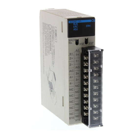
omron CS1W-AD041-V1 Manuals
Manuals and User Guides for omron CS1W-AD041-V1. We have
1
omron CS1W-AD041-V1 manual available for free PDF download: Operation Manual
omron CS1W-AD041-V1 Operation Manual (427 pages)
SYSMAC CS/CJ Series
Brand:
omron
| Category:
I/O Systems
| Size: 6.17 MB
Table of Contents
Table of Contents
6
Precautions
16
General Precautions
17
Intended Audience
17
Safety Precautions
17
Operating Environment Precautions
18
Application Precautions
19
EC Directives
20
Other Applicable Directives
21
Precautions for the C200H-AD003, C200H-DA003/004, and C200H-MAD01
21
Changes to the CJ1W-DA08V/08C and CJ1W-MAD42
22
Section 1
24
System Design
24
Features and Functions
25
Basic Configuration
30
Mounting Procedure
32
Precautions
34
Function Applications
35
Section 2 Cs-Series Analog Input Units
36
CS-Series Analog Input Units
36
Specifications
36
Operating Procedure
36
Components and Switch Settings
36
Wiring
36
Exchanging Data with the CPU Unit
36
Analog Input Functions and Operating Procedures
36
Adjusting Offset and Gain
36
Specifications
37
Input Function Block Diagram
40
Input Specifications
40
Operating Procedure
43
Procedure Examples
44
Components and Switch Settings
50
Indicators
51
Unit Number Switch
52
Operation Mode Switch
53
Voltage/Current Switch (CS1W-AD041-V1/AD081-V1)
54
Wiring
55
Terminal Arrangement
55
Internal Circuitry
56
Voltage Input Disconnection
58
Input Wiring Example
59
Input Wiring Considerations
61
Exchanging Data with the CPU Unit
62
Outline of Data Exchange
62
Unit Number Settings
63
Fixed Data Allocations
64
Special I/O Unit Restart Bits
64
I/O Refresh Data Allocations
69
Analog Input Functions and Operating Procedures
75
Input Settings and Conversion Values
75
Conversion Time/Resolution Setting
77
Mean Value Processing
78
Peak Value Hold Function
81
Input Disconnection Detection Function
82
Scaling Function (CS1W-AD161 Only)
83
Adjusting Offset and Gain
83
Adjustment Mode Operational Flow
83
Input Offset and Gain Adjustment Procedures
85
Handling Errors and Alarms
92
Indicators and Error Flowchart
92
Alarms Occurring at the Analog Input Unit
93
Errors in the CPU Unit
96
Restarting Special I/O Units
97
Troubleshooting
97
Section 3 Cj-Series Analog Input Units
100
Specifications
101
Input Function Block Diagram
103
Input Specifications
103
Operating Procedure
106
Procedure Examples
107
Components and Switch Settings
112
Indicators
113
Unit Number Switch
113
Operation Mode Switch
114
Voltage/Current Switch
115
Wiring
116
Terminal Arrangement
116
Internal Circuitry
117
Voltage Input Disconnection
118
Input Wiring Example
119
Input Wiring Considerations
119
Exchanging Data with the CPU Unit
120
Outline of Data Exchange
120
Unit Number Settings
121
Special I/O Unit Restart Bits
121
Fixed Data Allocations
122
I/O Refresh Data Allocations
124
Analog Input Functions and Operating Procedures
127
Input Settings and Conversion Values
127
Conversion Time/Resolution Setting
129
Mean Value Processing
130
Peak Value Hold Function
133
Input Disconnection Detection Function
134
Adjusting Offset and Gain
135
Adjustment Mode Operational Flow
135
Input Offset and Gain Adjustment Procedures
137
Handling Errors and Alarms
143
Indicators and Error Flowchart
143
Alarms Occurring at the Analog Input Unit
144
Errors in the CPU Unit
146
Restarting Special I/O Units
147
Troubleshooting
147
Section 4 Cs-Series Analog Output Units
148
CS-Series Analog Output Units
148
Specifications
149
Output Function Block Diagram
151
Output Specifications
151
Operating Procedure
153
Procedure Examples
154
Components and Switch Settings
159
Indicators
160
Operation Mode Switch
161
Unit Number Switch
161
Wiring
162
Terminal Arrangement
162
Internal Circuitry
163
Output Wiring Example
164
Exchanging Data with the CPU Unit
165
Outline of Data Exchange
165
Output Wiring Considerations
165
Special I/O Unit Restart Bits
166
Unit Number Settings
166
Fixed Data Allocations
167
I/O Refresh Data Allocations
169
Analog Output Functions and Operating Procedures
172
Output Settings and Conversions
172
Starting and Stopping Conversion
174
Output Hold Function
175
Output Setting Errors
176
Adjusting Offset and Gain
176
Adjustment Mode Operational Flow
176
Output Offset and Gain Adjustment Procedures
178
Handling Errors and Alarms
186
Indicators and Error Flowchart
186
Alarms Occurring at the Analog Output Unit
187
Errors in the CPU Unit
188
Restarting Special I/O Units
189
Troubleshooting
190
Section 5 Cj-Series Analog Output Unit
192
CJ-Series Analog Output Unit
192
Specifications
193
Output Function Block Diagram
195
Output Specifications
195
Operating Procedure
197
Procedure Examples
199
Components and Switch Settings
205
Indicators
206
Unit Number Switch
206
Operation Mode Switch (DA021/041)
207
Wiring
207
Terminal Arrangement
207
Internal Circuitry
209
Output Wiring Considerations
210
Output Wiring Example
210
Exchanging Data with the CPU Unit
211
Outline of Data Exchange
211
Special I/O Unit Restart Bits
212
Unit Number Settings
212
Fixed Data Allocations
213
I/O Refresh Data Allocations
216
Analog Output Functions and Operating Procedures
220
Output Settings and Conversions
220
Conversion Time/Resolution Setting (CJ1W-DA08V/08C Only)
222
Starting and Stopping Conversion
222
Output Hold Function
223
Output Scaling Function (CJ1W-DA08V/08C Only)
224
Output Setting Errors
226
Adjusting Offset and Gain
227
Adjustment Mode Operational Flow
227
Output Offset and Gain Adjustment Procedures
230
Handling Errors and Alarms
238
Indicators and Error Flowchart
238
Alarms Occurring at the Analog Output Unit
239
Errors in the CPU Unit
241
Restarting Special I/O Units
242
Troubleshooting
242
Section 6 Cs-Series Analog I\/O Unit
244
CS-Series Analog I/O Unit
244
Specifications
245
I/O Function Block Diagram
248
Input Specifications
248
Output Specifications
250
Operating Procedure
253
Procedure Examples
254
Components and Switch Settings
260
Indicators
261
Operation Mode Switch
262
Unit Number Switch
262
Voltage/Current Switch
263
Wiring
263
Terminal Arrangement
263
Internal Circuitry
264
Voltage Input Disconnection
265
I/O Wiring Example
266
I/O Wiring Considerations
267
Exchanging Data with the CPU Unit
267
Outline of Data Exchange
267
Special I/O Unit Restart Bits
268
Unit Number Settings
268
Fixed Data Allocations
269
I/O Refresh Data Allocations
272
Analog Input Functions and Operating Procedures
275
Input Settings and Conversion Values
275
Mean Value Processing
277
Peak Value Hold Function
280
Input Disconnection Detection Function
281
Analog Output Functions and Operating Procedures
282
Output Settings and Conversions
282
Output Hold Function
284
Ratio Conversion Function
285
Output Setting Errors
285
Adjusting Offset and Gain
288
Adjustment Mode Operational Flow
289
Input Offset and Gain Adjustment Procedures
290
Output Offset and Gain Adjustment Procedures
296
6-10 Handling Errors and Alarms
304
6-10-1 Indicators and Error Flowchart
304
6-10-2 Alarms Occurring at the Analog I/O Unit
305
6-10-3 Errors in the CPU Unit
307
6-10-4 Restarting Special I/O Units
308
6-10-5 Troubleshooting
308
Section 7 Cj-Series Analog I\/O Unit
310
CJ-Series Analog I/O Unit
310
Specifications
311
I/O Function Block Diagram
313
Input Specifications
314
Output Specifications
316
Operating Procedure
318
Procedure Examples
319
Components and Switch Settings
325
Indicators
326
Unit Number Switch
326
Voltage/Current Switch
327
Wiring
328
Internal Circuitry
328
Terminal Arrangement
328
Voltage Input Disconnection
330
I/O Wiring Example
331
I/O Wiring Considerations
332
Exchanging Data with the CPU Unit
332
Outline of Data Exchange
332
Operation Mode Setting
333
Unit Number Settings
333
Special I/O Unit Restart Bits
334
Fixed Data Allocations
335
I/O Refresh Data Allocations
338
Analog Input Functions and Operating Procedures
341
Input Settings and Conversion Values
341
Conversion Time and Resolution Setting
343
Mean Value Processing
343
Peak Value Hold Function
346
Input Scaling Function
347
Input Disconnection Detection Function
349
Analog Output Functions and Operating Procedures
350
Output Settings and Conversions
350
Conversion Time and Resolution Setting
352
Output Hold Function
353
Output Scaling Function
354
Output Setting Errors
356
Ratio Conversion Function
356
Adjusting Offset and Gain
359
Adjustment Mode Operational Flow
360
Input Offset and Gain Adjustment Procedures
361
Output Offset and Gain Adjustment Procedures
367
7-10 Handling Errors and Alarms
375
7-10-1 Indicators and Error Flowchart
375
7-10-2 Alarms Occurring at the Analog I/O Unit
376
7-10-3 Errors in the CPU Unit
378
7-10-4 Restarting Special I/O Units
379
7-10-5 Troubleshooting
379
Dimensions
382
Sample Programs
386
Data Memory Coding Sheets
396
Index
418
Revision History
424
Advertisement
Advertisement
Related Products
omron CS1W-AD081-V1
omron CS1W-AD161
omron CS1W-DA08V
omron CS1W-DA08C
omron CS1W-MAD44
OMRON SYSMAC CS1W-PRM21
Omron SYSMAC CS1W-PTS02
Omron SYSMAC CS1W-PTW01
Omron SYSMAC CS1W-PTR02
Omron SYSMAC CS1W-PPS01
omron Categories
Blood Pressure Monitor
Controller
Accessories
Switch
Inverter
More omron Manuals
Login
Sign In
OR
Sign in with Facebook
Sign in with Google
Upload manual
Upload from disk
Upload from URL