Sign In
Upload
Manuals
Brands
Omron Manuals
Controller
CK3M Seres
Omron CK3M Seres Manuals
Manuals and User Guides for Omron CK3M Seres. We have
1
Omron CK3M Seres manual available for free PDF download: Hardware User Manual
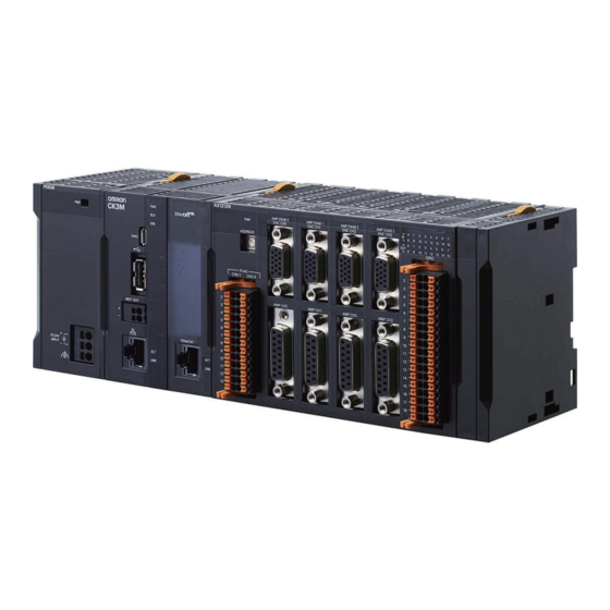
Omron CK3M Seres Hardware User Manual (302 pages)
Programmable Multi-Axis Controller
Brand:
Omron
| Category:
Controller
| Size: 12.07 MB
Table of Contents
Table of Contents
8
Intended Audience
3
Applicable Products
3
Manual Structure
4
Page Structure
4
Special Information
5
Sections in this Manual
7
Table of Contents
8
Terms and Conditions Agreement
13
Warranty, Limitations of Liability
13
Application Considerations
14
Disclaimers
14
Statement of Security Responsibilities for Assumed Use Cases and against Threats
15
Safety Precautions
16
Definition of Precautionary Information
16
Symbols
16
Warning
17
Cautions
21
Precautions for Safe Use
22
Precautions for Correct Use
27
Regulations and Standards
29
Conformance to EU Directives
29
Condition for Compliance with EU Directives
29
Conformance to KC Certification
30
Conformance to UL and CSA Standards
30
Versions
31
Checking Versions
31
Related Manuals
33
Terminology
34
Revision History
35
Introduction to Motion Controllers
37
Features and System Configuration
38
Motion Controller Features
38
Introduction to the System Configurations
38
Basic Configuration
39
Support Software
39
Ethercat Network Configuration
40
Connecting to the Power PMAC IDE
50
Ethernet Network Configuration
51
CPU Unit
55
Models and Specifications
55
Part Names and Functions
58
Operation Status Indicators
59
Watchdog Output Terminal Block
60
USB Memory Device
61
Power Supply Unit
63
Models and Specifications
63
Part Names and Functions
64
Axis Interface Unit
65
Models and Specifications
65
Part Names and Functions
67
Operation Status Indicators
68
Address Switch Setting
69
Encoder Connector Specifications
69
Encoder Loss Detection
75
Pulse Input Timing Specifications for Digital Quadrature Encoder
76
Input Specifications for Sinusoidal Encoder
78
Outflag Function
80
Amplifier Connector Specifications
81
Output Method
84
Directpwm Output Method
85
Flag Connection Terminal Block Specifications
86
General Digital I/O Connection Terminal Block Specifications
91
Digital I/O Unit
98
Models and Specifications
98
Part Names and Functions
102
Operation Indicators
103
Address Switch Setting
103
Terminal Arrangement
104
I/O Data
105
Analog Input Unit
107
Models and Specifications
107
Part Names and Functions
108
Operation Indicators
109
Address Switch Setting
109
Terminal Arrangement
110
Analog Input Data
111
Input Filter
112
Encoder Input Unit
114
Models and Specifications
114
Address Switch Setting
116
Operation Indicators
116
Part Names and Functions
116
Terminal Arrangement
117
Software Settings
117
Installation
147
Power off Operation
148
Power on Operation
148
Processing at Power on and Power off
148
Fail-Safe Circuits
150
Installation in a Control Panel
152
Unit Installation
152
Connection between Units
156
Mounting to DIN Track
157
DIN Track and Accessories
159
Control Panel Installation
166
Temperature
166
Humidity
167
Atmosphere
168
Electrical Environment
168
Vibration and Shock
168
Grounding
173
Wiring
179
Applicable Wires
180
Power Supply Unit CK3W-PD048
180
Power Supply Used
180
Power Supply Wiring
180
Grounding
181
Connecting Ferrules
182
Connecting Twisted Wires/Solid Wires
182
Required Tools
182
Removing Wires
183
CPU Unit Wiring
185
Laying the Ethercat Network
185
Laying the Ethernet Network
190
Watchdog Timer Output Wiring
192
USB Memory Device Connection
195
Axis Interface Unit Wiring
196
Encoder Connector Wiring
196
Amplifier Connector Wiring
202
Flag Terminal Block/General I/O Terminal Block Wiring
204
Digital I/O Unit Wiring
211
Wiring the Terminals
211
Precautions When Connecting a Two-Wire DC Sensor
214
Precautions When Connecting to Digital Output
216
Analog Input Unit Wiring
218
Wiring the Terminals
218
Dedicated Cable
222
Encoder Connector Wiring
222
Encoder Input Unit
222
Galvo Scanner Connector Wiring
224
Laser Interface Unit
224
Laser Connector Wiring
226
Expansion Master Unit and Expansion Slave Unit Wiring
228
Troubleshooting
229
Types of Errors
230
Indicator Types
231
Procedure for Identifying Errors
231
Using the Indicators to Check Errors
231
Fatal Errors in the CPU Unit
233
Troubleshooting for Errors
233
Non-Fatal Errors in the CPU Unit
234
Initialization of CPU Unit Using USB Memory
237
Sys.status Register
238
Sys.status Register List
238
Details of Flags
239
Ethernet/Ip Connection Status Codes and Troubleshooting
249
Appendices
257
A-1 General Specifications
259
A-2 Dimensions
260
A-2-1 CPU Unit
260
Axis Interface Unit
261
Power Supply Unit
261
CK3W-MD and CK3W-AD Units
262
CK3W-ECS and CK3W-GC Units
263
Expansion Master Unit and Expansion Slave Unit
264
A-2-7 End Cover
265
Restrictions on Using the NX-Series Ethercat Coupler Unit
266
OMRON Servo Drive Connection Example
267
A-5 Version Information
268
A-6 How to Read the Lot Number
269
A-7 Supported CIP Objects
270
A-7-1 Identity Object (Class ID: 01 Hex
270
Assembly Object (Class ID: 04 Hex
271
TCP/IP Interface Object (Class ID: F5 Hex
272
Ethernet Link Object (Class ID: F6 Hex
273
A-8-1 Gate3[I].Serialencctrl (Serial Encoder Control
277
Software Reference of Encoder Input Unit
277
Gate3[I].Chan[J].Serialenccmd (Serial Encoder Command
280
Gate3[I].Chan[J].Serialencena (Serial Encoder Enable
280
Gate3[I].Chan[J].Serialencdataa (Serial Encoder Data a
283
Gate3[I].Chan[J].Serialencdatab (Serial Encoder Data B
284
Gate3[I].Chan[0].Status (Internal Memory Error Detection
287
Gate3[I].Serialencctrl (Control Register
289
Software Reference of Laser Interface Unit
289
Gate3[I].Chan[J].Dac[0] (Setting of Command Position and Control Command
290
Gate3[I].Chan[J].Dac[1] (Setting of Command Position Compensa- Tion Value
291
Gate3[I].Chan[J].Serialencdataa (Command Position after Interpola- Tion, Reception Data
291
Gate3[I].Chan[J].Serialencdatab (Status Data
292
Gate3[I].Chan[0].Compa (PWM Output Setting
293
Gate3[I].Chan[1].Compa (PWM Output Delay Setting
294
Gate3[I].Chan[2].Compa (PWM Output Pulse Count
294
A-9-10 Gate3[I].Chan[1].Compb (TCR Output Comparison Table Setting
295
A-9-11 Gate3[I].Chan[2].Compb (TCR Output Control Register
295
Gate3[I].Chan[0].Compb (TCR Output Command Distance Setting
295
A-9-12 Gate3[I].Chan[3].Compb (TCR Output Status Register
296
A-9-13 Gate3[I].Chan[0].Status (Internal Memory Error Detection
296
Advertisement
Advertisement
Related Products
Omron CK3M Series
Omron CK3M-CPU1 1 Series
Omron CK3M-CPU101
Omron CK3M-CPU121
Omron CK3M-CPU111
Omron CK3M-CPU 1 Series
Omron CK3E-1410
Omron CK3W-AX1515P
Omron CK3W-AD2100
Omron CK3W-GC2200
Omron Categories
Blood Pressure Monitor
Controller
Accessories
Switch
Inverter
More Omron Manuals
Login
Sign In
OR
Sign in with Facebook
Sign in with Google
Upload manual
Upload from disk
Upload from URL