Fluke 5730A/03 Manuals
Manuals and User Guides for Fluke 5730A/03. We have 2 Fluke 5730A/03 manuals available for free PDF download: Operator's Manual, Sales Manual
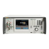
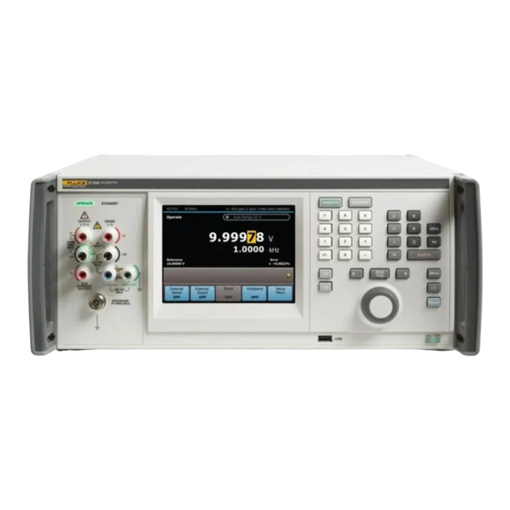
Fluke 5730A/03 Operator's Manual (248 pages)
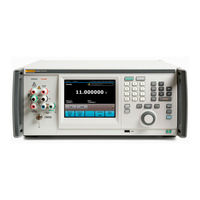
Multifunction Calibrator
Brand: Fluke
|
Category: Test Equipment
|
Size: 6.3 MB
Table of Contents
Advertisement
Fluke 5730A/03 Sales Manual (28 pages)
Multifunction Calibrator
Brand: Fluke
|
Category: Test Equipment
|
Size: 0.93 MB
Table of Contents
Advertisement