Daikin RKS25E2V1B Manuals
Manuals and User Guides for Daikin RKS25E2V1B. We have 7 Daikin RKS25E2V1B manuals available for free PDF download: Service Manual, Installation Manual
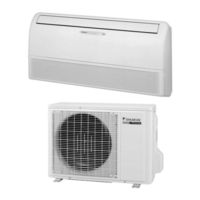
Daikin RKS25E2V1B Service Manual (232 pages)
Inverter Pair Floor/Ceiling Suspended Dual Type BA Series
Brand: Daikin
|
Category: Air Conditioner
|
Size: 11.93 MB
Table of Contents
Advertisement

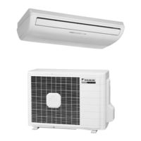
Daikin RKS25E2V1B Service Manual (144 pages)
Inverter Pair Floor / Ceiling Suspended Dual Type
FLK(X)S-BA Series
Brand: Daikin
|
Category: Air Conditioner
|
Size: 4.72 MB
Table of Contents
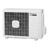
Daikin RKS25E2V1B Service Manual (137 pages)
Inverter Pair Floor / Ceiling Suspended Dual Type BA-Series
Brand: Daikin
|
Category: Air Conditioner
|
Size: 3.16 MB
Table of Contents
Advertisement

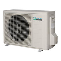
Daikin RKS25E2V1B Service Manual (26 pages)
REMOVAL PROCEDURE
Brand: Daikin
|
Category: Air Conditioner
|
Size: 1.91 MB
Table of Contents
Daikin RKS25E2V1B Service Manual (26 pages)
Brand: Daikin
|
Category: Air Conditioner
|
Size: 1.88 MB
Table of Contents
Daikin RKS25E2V1B Installation Manual (15 pages)
R410A Split Series
Brand: Daikin
|
Category: Air Conditioner
|
Size: 1.4 MB
Table of Contents

Daikin RKS25E2V1B Installation Manual (15 pages)
Brand: Daikin
|
Category: Air Conditioner
|
Size: 1.44 MB
Table of Contents
Advertisement