Sign In
Upload
Manuals
Brands
Agilent Technologies Manuals
Analytical Instruments
E4448A
Agilent Technologies E4448A Manuals
Manuals and User Guides for Agilent Technologies E4448A. We have
9
Agilent Technologies E4448A manuals available for free PDF download: Service Manual, User And Programming Manual, Manual, Getting Started Manual, Installation Manual
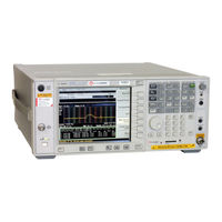
Agilent Technologies E4448A Service Manual (436 pages)
Spectrum Analyzer
Brand:
Agilent Technologies
| Category:
Measuring Instruments
| Size: 3.17 MB
Table of Contents
Table of Contents
5
Overview
13
What You will Find in this Chapter
14
Agilent PSA Series Spectrum Analyzer Overview
15
Instrument Hardware Option Descriptions
16
Before Troubleshooting a Failure
19
ESD Information
19
Service Equipment You will Need
22
Service Kit Parts List
22
Required Test Equipment List
24
Replacement Assemblies
34
Battery Information
36
After an Instrument Repair
36
Contacting Agilent Technologies
37
Instrument Serial Numbers
39
How to Return Your Instrument for Service
40
Overall Troubleshooting What You will Find in this Chapter
44
Check the Basics
45
Troubleshooting Power-Up Problems
46
Troubleshooting an Inoperative Instrument
47
Check the Instrument Setup
47
Initial Checks
47
Troubleshooting Using Auto-Align Tests
49
Quick Cals
52
Isolating the Faulty Assembly When the Displayed Amplitude Is Incorrect or the Instrument Fails a Gain Related Auto Align Test
53
Troubleshooting Using Front Panel Keys
57
Error Messages
57
Using Service Features
58
Using Alignment Features
62
Selecting the Frequency Reference
64
User Diagnostics
64
Restore System Defaults
64
Troubleshooting Performance Test Failures
65
Section 1
70
Troubleshooting the RF Section (E4440A, E4443A, E4445A) What You will Find in this Chapter
70
(E4440A, E4443A, E4445A)
71
RF Section Description
71
RF Section Description (E4440A, E4443A, E4445A)
71
E4440A, E4443A, E4445A
75
Overall Front End
75
RF Assembly Quick Check - E4440A, E4443A, E4445A
75
Verifying a Faulty Front End Assembly
75
A14 and A15 Step Attenuators
76
A21 Switched lo Distribution Amplifier (SLODA)
78
A19 Rythm
80
A18 Yto
81
A20 Lowband
82
A13 Front End Driver
84
A22 Low Band Preamplifier (Option 1DS)
86
A27 Electronic Attenuator Description (Option B7J)
87
Section 2
90
Troubleshooting the RF Section (E4446A, E4447A, E4448A)
90
(E4446A, E4447A, E4448A)
91
RF Section Description (E4446A, E4447A, E4448A)
91
E4446A, E4447A, E4448A
95
Overall Front End
95
RF Assembly Quick Check - E4446A, E4447A, E4448A
95
Verifying a Faulty Front End Assembly
95
A14 and A15 Step Attenuators
96
A21 FELOMA and A29 FELOMA/SBTX Driver
98
A19 SBTX/RYTHM Assembly
101
A18 Yto
103
A20 Lowband
104
A13 Front End Driver
107
A22 Low Band Preamplifier (Option 1DS)
108
A27 Electronic Attenuator Description (Option B7J)
109
Troubleshooting the Synthesizer Section
111
What You will Find in this Chapter
112
A12 Synthesizer Assembly Description
113
Troubleshooting lo and Sampling Oscillator Unlock Conditions
114
Verifying the A12 Synthesizer Board
114
E4440-60049 Extender Board
116
A11 Reference Assembly Description
118
100 Mhz VCXO
119
300 Mhz Outputs
119
50 Mhz Calibrator Output
119
Interconnections to Other Assemblies
119
Reference Unlock Detector
119
Reference Assembly Quick Check
120
Verifying the A11 Reference Board
120
Reference Assembly Detailed Troubleshooting
121
A9 Second Lo/Fan Control Assembly Description
122
Fan Control Circuitry
122
Second lo Circuitry
122
If the Fans Are Not Operating
123
Verifying the A9 2Nd LO/ Fan Control Board
123
Troubleshooting the if Section
125
What You will Find in this Chapter
126
321.4 Mhz Filter
127
50 Mhz Calibrator ALC
127
A10 Third Converter Assembly Description
127
Linearization Circuit
127
Step Attenuator
127
System Variable Gain Compensation Circuitry
127
321.4 Mhz Cal Signal Mixer
128
3Rd Mixer
128
Interconnections to Other Assemblies
128
Third Converter Troubleshooting
129
Verifying the A10 Third Converter Board
129
Verifying the A10 Third Converter Board E4440A, E4443A, E4445A, E4446A, E4448A)
129
(E4447A)
131
Third Converter Troubleshooting
131
A8 Analog if Assembly Description
133
Main Gain Amplifier
133
Pre-Filters
133
21.4 Mhz Anti-Alias Filter
134
Calibration Generator
134
Clock Generator
134
Fourth L.O
134
Mixer
134
Post down Conversion Filtering
134
Interconnections to Other Assemblies
135
Power Supply Switching Reference
135
Triggering
135
Analog if Assembly Quick Check
136
Verifying the A8 Analog if Assembly Signal Path
136
Analog if Assembly Detailed Troubleshooting
137
7.5 Mhz if
139
A7 Digital if Assembly Descriptions
139
Gain Range Select/Rules
139
Offset Adjust and Dither
139
Interconnections to Other Assemblies
140
Digital if Assembly Quick Check
141
Verifying the A7 Digital if Board
141
Digital if Assembly Detailed Troubleshooting
142
Troubleshooting the Processor, Power Supply, and Display What You will Find in this Chapter
146
A25 Motherboard Description
147
A26 CPU Assembly Description
148
CPU Assembly Quick Check
149
Verifying the A26 CPU Assembly
149
Battery Information
152
CPU Assembly Detailed Troubleshooting
152
A5 Power Supply Assembly Description
153
Isolating an A5 Power Supply Problem
154
Verifying the Individual Voltage Supplies
155
A6 SCSI Interface Board Description
158
A1 LCD Display
159
A2 Front Panel Interface Assembly
159
A23 Disk Drive
159
A3 Keyboard
159
Front Frame Description
159
Isolating a Display Problem
160
Verifying the Inverter Boards
160
Verifying HSYNC, VSYNC, and LCD Clock
162
Rear Panel Description
164
Hardware Options
165
What You will Find in this Chapter
166
Verifying Option 107 Audio Input
167
Verification of Option 107
168
Verification of Option 110
169
Verifying Option 110
169
(All PSA Series)
172
Overview of Option 115 Extended Memory
172
Verification of Option 115
173
Verifying Option 122 or 140, Wide Bandwidth Digitizer
174
Setting up the Instrument in Wideband Mode
175
Setting up the Instrument in Narrow Band Mode
176
If the Problem Only Exists in the Wideband Path
177
Viewing the Wide Band Response to a Comb Signal (Inner Loop Test)
178
Viewing the Wide Band Response to a Comb Signal (Outer Loop Test)
179
Wide Band Analog if Assembly Filter Path Test
181
Option 122 or 140 Lowband Filters
183
Overview and Verification of Option 123, Microwave and Millimeter Preselector Bypass
187
Overview of Option 123 in the E4440A, E4443A, or E4445A
187
Overview of Option 123 in the E4446A, E4447A, or E4448A
197
Procedure 1 - Quick Check of Video out Level
203
Verifying Option 124, Y-Axis Video out
203
Procedure 2 - Detailed View of the Video Signal
204
Block Diagrams What You will Find in this Chapter
208
Signal Mnemonics
209
Overall Block Diagrams
212
Replaceable Parts Lists and Locations
221
What You will Find in this Chapter
222
Replaceable Parts
224
Hardware
249
Assembly Replacement Procedures
305
Section 3
306
What You will Find in this Chapter
306
Before Starting
307
Safety
307
Adjustments after an Instrument Repair
308
Tools You will Need
308
Major Assembly Locations
309
Instrument Outer Case
310
Outer Case
310
Removal
310
Replacement
311
Removal
312
Top Brace
312
Replacement
313
Drop the Front Frame
314
Front Frame
314
Removal
315
Replacement
316
Complete RF Section
317
E4440A, E4443A, E4445A
317
RF Section
317
RF Section and Assemblies (E4440A,E4443A,E4445A)
317
E4440A, E4443A, E4445A
320
RF Assemblies
320
A18 YTO and A19 RYTHM
322
A21 Sloda
323
FL1 Low Pass Filter
323
A20 Lowband
324
FL2 Band Pass Filter
324
E4440A, E4443A, E4445A
325
RF Section Option Assemblies
325
A22 Preamplifier
326
A27 Electronic Attenuator
326
(E4440A, E4443A, E4445A)
327
Option 110 Assemblies
327
A36 Preamplifier
329
Option 123 Assemblies
330
Complete RF Section
336
E4446A, E4447A, E4448A
336
RF Section
336
RF Section and Assemblies (E4446A, E4447A, E4448A)
336
E4446A, E4447A, E4448A
339
RF Assemblies
339
A18 YTO and A19 SBTX/RYTHM
341
A21 Feloma
342
FL1 Low Pass Filter
342
A20 Lowband
343
A20 Lowband (E4446A, E4448A)
343
FL2 Band Pass Filter
343
A20 Lowband (E4447A Only)
344
A29 LOMA/SBTX Driver
345
A29 SBTX Driver Board
345
A30 Fifa
345
E4446A, E4447A, E4448A
346
RF Section Option Assemblies
346
A22 Preamplifier
347
A27 Electronic Attenuator
347
E4446A, E4447A, E4448A
348
Option 110 Assemblies
348
SW4 Millimeter Switch
351
A34 Mixer
352
E4446A, E4447A, E4448A
352
Option 123 Assemblies
352
A35 Mixer Bias Board
353
SW3 Switch
353
SW5 Switch
355
Assembly
357
Attenuator Assembly
357
E4440A, E4443A, E4445A
357
Removal
357
Replacement
358
Attenuator Assembly
359
E4446A, E4447A, E4448A
359
Removal
359
Replacement
360
A5 Power Supply
361
Removal
361
Replacement
362
A39 Usb/Memory Board
363
Removal
363
Replacement
365
A6 SCSI Board
366
A6 SCSI Board (Early Instruments)
366
Removal
366
Replacement
366
(Standard Instrument)
367
Vertical Board Assemblies
367
Removal
371
(E4447A Only)
372
A10 Third Converter Removal Procedure
372
Replacement
372
Fans
374
Fans/MID Web
374
MID-Web and Fan Assemblies
374
MID Web
376
A23 Disk Drive
378
Removal
378
Replacement
381
A25 Motherboard
382
Removal
382
Replacement
384
A26 CPU Assembly
385
Removal
385
Battery Replacement
387
Replacement
387
A26A1 DRAM and A26A2 Flash Boards
388
Removal
388
Replacement
389
Rear Frame
390
Removal
390
Replacement
392
Removal
393
RF Input Connector
393
Replacement
394
Front Frame Subassemblies
395
Front Frame Exploded View
397
A1 Display and Filter
398
A1 LCD Display, Backlights, and Filter
398
A2 Front Panel Interface Board
402
Bezel and Keypad
404
External Trigger Cable
407
Rpg
407
Post-Repair Procedures
409
What You will Find in this Chapter
410
Before Starting
411
Test Equipment You will Need
411
Post-Repair Procedures
412
Burst Trigger Check
419
Internal Front Panel Test
420
28 V Rear Panel Output Check
421
Configuring a Replacement CPU Assembly
422
Description
422
Procedure
422
Configuring a Replacement Flash Memory Assembly
425
Description
425
Equipment Required
425
Procedure
426
Firmware Upgrades
429
Firmware Upgrades Including Measurement Personality Upgrades
430
Advertisement
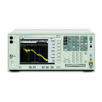
Agilent Technologies E4448A User And Programming Manual (434 pages)
Spectrum Analyzers
Brand:
Agilent Technologies
| Category:
Measuring Instruments
| Size: 7.15 MB
Table of Contents
Table of Contents
3
1 Using this Document
27
About the User's and Programmer's Information
28
What Is in this Book
28
Terms Used in this Book
29
2 Instrument Functions: a − L
31
AMPLITUDE / y Scale
33
Ref Level
33
Attenuation
34
Scale/DIV
35
Scale Type
36
Presel Center
37
Presel Adjust
38
Y Axis Units
41
Ref Lvl Offset
47
Int Preamp
48
Corrections
49
Ext Amp Gain
55
Atten Step
56
Max Mixer Lvl
56
Auto Couple
57
Auto All
57
FFT & Sweep
58
Phnoise Opt
63
Detector
65
Avg/Vbw Type
65
ADC Dither
65
ADC Ranging
67
Bw/Avg
69
Res BW
69
Video BW
71
Vbw/Rbw
72
Average
73
Avg/Vbw Type
74
Span/Rbw
78
Det/Demod
79
Detector
79
Display
91
Full Screen
91
Display Line
92
Active Fctn Position
93
Limits
97
Title
110
Preferences
111
Display Enable (Remote Command Only)
112
File
113
Catalog
116
Save
120
Load
127
Delete
132
Copy
133
Rename
135
Create dir
137
Delete All
139
Query Trace Data (Remote Command Only)
139
Move Data to a File (Remote Command Only)
140
Set Data Byte Order (Remote Command Only)
141
Format Numeric Data (Remote Command Only)
141
FREQUENCY / Channel
143
Center Freq
144
Start Freq
145
Stop Freq
146
CF Step
147
Freq Offset
148
Signal Track
149
Input/Output
151
Input Port
151
RF Coupling
152
Input Mixer (Option AYZ Only)
152
Mhz if out Opt
153
Microwave Preselector
154
Ext MIX Band (Option AYZ Only)
155
Signal ID (Option AYZ Only)
160
Signal ID Mode
161
Mixer Config
162
3 Instrument Functions: M − O
165
Marker
167
Select Marker
169
Normal
169
Delta
170
Delta Pair
171
Span Pair
172
Off
174
Marker Trace
175
Readout
176
Marker Table
178
Marker All off
178
Marker Fctn
179
Select Marker
179
Marker Noise
179
Band/Intvl Power
181
Function off
182
Marker Count
182
Marker
185
Mkr->CF
185
Mkr->CF Step
185
Mkr->Start
186
Mkr->Stop
186
Mkr∆->Span
187
Mkr∆->CF
187
Mkr->Ref Lvl
188
MEASURE (Spectrum Analysis Mode)
189
Measurement Setup
190
Meas Control
191
Restart
191
Measure
192
Pause or Resume
192
Trigger a Sweep or Measurement (Remote Command Only)
193
Abort the Sweep or Measurement (Remote Command Only)
194
MODE and Mode Setup
195
Spectrum Analysis
196
Application Mode Number Selection (Remote Command Only)
197
Application Mode Catalog Query (Remote Command Only)
198
Mode Setup (Spectrum Analysis Mode)
199
4 Instrument Functions: P − Z
201
Peak Search
203
Next Peak
204
Next Pk Right
204
Next Pk Left
205
Min Search
205
Pk-Pk Search
205
Mkr->CF
206
Continuous Pk
206
Search Param
206
Preset
211
User Preset
212
Mode Preset
213
Factory Preset
213
Save User Preset
214
Print
215
Abort the Printout (Remote Command Only)
215
Print Setup
216
Restart
221
Save
223
Single
225
SPAN / X Scale
227
Span
227
Span Zoom
228
Full Span
228
Zero Span
228
Last Span
229
Sweep
231
Sweep Time
231
Sweep
232
Auto Sweep Time
233
Gate
234
Gate Setup
235
Points
240
System
241
Show Errors
241
Power On/Preset
244
Time/Date
248
Alignments
251
Config I/O
257
Reference
262
Show System
264
Show Hdwr
265
Color Palette
265
Diagnostics
267
Restore Sys Defaults
268
Licensing
269
Personality
273
Service
274
Keyboard Lock (Remote Command Only)
274
Remote Message
275
Remote Message Turned off
275
Power on Elapsed Time (Remote Command Only)
275
SCPI Version Query (Remote Command Only)
276
Trace/View
277
Query Trace Data (Remote Command Only)
278
Trace
278
Clear Write
279
Max Hold
279
Min Hold
279
View
280
Blank
280
Trig
281
Free Run
281
Video
282
Line
283
Ext Front (Ext Trig In)
283
Ext Rear (Trigger In)
283
RF Burst (Wideband)
284
Trig Slope
284
Trig Delay
285
Trig Offset (Remote Command Only)
285
5 Programming Fundamentals
287
SCPI Language Basics
289
Command Keywords and Syntax
289
Creating Valid Commands
289
Special Characters in Commands
290
Parameters in Commands
292
Putting Multiple Commands on the same Line
294
Improving Measurement Speed
297
Turn off the Display Updates
297
Use Binary Data Format Instead of ASCII
297
Minimize the Number of GPIB Transactions
298
Avoid Unnecessary Use of *RST
298
Put ADC Ranging in Bypass for FFT Measurements
299
Minimize Dut/Instrument Setup Changes
299
Consider Using LAN Instead of GPIB
299
Using an Option Mode: Minimize the Number of GPIB Transactions
299
Using an Option Mode: Avoid Automatic Attenuator Setting
300
Using an Option Mode: Avoid Using Rfburst Trigger for Single Burst Signals
301
Using an Option Mode: When Making Power Measurements on Multiple Bursts or Slots, Use Calculate:data<N>:Compress
302
Programming Command Compatibility Across Model Numbers and Across Modes
304
Across PSA Modes: Command Subsystem Similarities
304
Across PSA Modes: Specific Command Differences
306
Using Applications in PSA Series Vs. VSA E4406A
307
Using the LAN to Control the Instrument
309
Using Ftp for File Transfers
309
Using Telnet to Send Commands
312
Using Socket LAN to Send Commands
315
Using SICL LAN to Control the Instrument
316
Using Hp/Agilent VEE over Socket LAN
321
Using a Java™ Applet over Socket LAN
323
Using a C Program over Socket LAN
323
General LAN Troubleshooting
324
Programming in C Using the VTL
333
Typical Example Program Contents
333
Linking to VTL Libraries
334
Compiling and Linking a VTL Program
334
Example Program
336
Including the VISA Declarations File
336
Opening a Session
337
Device Sessions
337
Addressing a Session
339
Closing a Session
340
Overview of the GPIB Bus
341
GPIB Command Statements
341
6 Using the Status System
343
Status System Commands
344
Using the Status Registers
347
What Status Registers Are
347
Why Use the Status Registers
349
Using a Status Register
351
Using the Service Request (SRQ) Method
351
Status Byte Register
355
Standard Event Status Register
358
Operation and Questionable Status Registers
361
Common Using the Status System IEEE Commands
363
Calibration Query
363
Clear Status
363
Standard Event Status Enable
364
Standard Event Status Register Query
364
Identification Query
364
Instrument State Query
365
Operation Complete
365
Query Instrument Options
366
Power-On Status Clear
366
Recall
367
Reset
367
Save
368
Service Request Enable
368
Read Status Byte Query
368
Trigger
369
Self Test Query
369
Wait-To-Continue
370
Status Subsystem
371
Operation Register
371
Preset the Status Byte
373
Questionable Register
373
Questionable Calibration Register
375
Questionable Frequency Register
377
Questionable Integrity Register
378
Questionable Integrity Signal Register
380
Questionable Integrity Uncalibrated Register
382
Questionable Power Register
383
Questionable Temperature Register
385
Agilent Technologies E4448A Manual (382 pages)
Spectrum Analyzer Measuring Receiver System Measuring Receiver Guide
Brand:
Agilent Technologies
| Category:
Measuring Instruments
| Size: 1.94 MB
Table of Contents
Table of Contents
3
List of Commands
17
Introduction
27
N5531S Measuring Receiver System Overview
28
N5531S System Block Diagram
29
What Does PSA Option 233 Measuring Receiver Personality Do
30
Do You Have Enough Memory to Load All Your Personality Options
31
Installing Optional Measurement Personalities
31
How to Predict Your Memory Requirements
33
Loading an Optional Measurement Personality
35
Obtaining and Installing a License Key
35
Viewing a License Key
36
Ordering Optional Measurement Personalities
37
Using the Delete License Key on PSA
37
Instrument Updates at Www.agilent.com
38
Installation and Setup
39
N5531S System Requirements
41
Measurements Availability Vs. Optional Hardware
42
Setting up the System
44
System Hardware Connections
44
System Configuration
47
System Configuration Using Using a LAN Cross-Over Cable
49
Verifying the System Connections
51
Calibrating System Components
52
Load Cal Factors
52
Edit Cal Factors
53
Zero and Calibrate the Power Meter
53
File Operations
54
When to Recalibrate
54
PSA Range Calibration
56
Protecting against Electrostatic Discharge
60
Making Measurements Measuring Receiver Measurements
62
Instrument Front Panel Highlights
63
Selected PSA Front-Panel Features
64
Mode Setup
65
Frequency Counter Measurement
66
Measurement Procedure
67
Frequency Counter Measurement Example
69
Measurement Procedure
70
RF Power Measurement
70
RF Power Measurement Example
73
Avoid Residual Responses
74
Tuned RF Level Measurement
74
Measurement Procedure
75
Tuned RF Level Measurement Example
81
AM Depth Measurement
82
Measurement Procedure
82
Measurement Settings
83
Adjusting the Detector, and High and Low Pass Filters
84
Adjusting the View
85
AM Depth Measurement Example
86
FM Deviation Measurement
87
Measurement Procedure
87
Measurement Settings
88
Adjusting the Detector, Auto Carrier Frequency, and High and Low Pass Filters
89
Adjusting the View
91
FM Deviation Measurement Example
91
Measurement Procedure
93
PM Deviation Measurement
93
Measurement Settings
94
Adjusting the Detector, Auto Carrier Frequency, and High and Low Pass Filters
95
Adjusting the View
97
PM Deviation Measurement Example
97
Measurement Procedure
99
Modulation Rate Measurement
99
Modulation Rate Measurement Example
101
Measurement Procedure
103
Modulation Distortion Measurement
103
Modulation Distortion Measurement Example
105
Measurement Procedure
107
Modulation SINAD Measurement
107
Modulation SINAD Measurement Example
109
Audio Frequency Measurement
111
Measurement Procedure
111
Audio AC Level Measurement
113
Measurement Procedure
113
Audio AC Level Measurement Example
114
Audio Distortion Measurement
115
Measurement Procedure
115
Audio Distortion Measurement Example
116
Audio SINAD Measurement
117
Measurement Procedure
117
Audio SINAD Measurement Example
118
Front-Panel Key and SCPI Command Reference
119
Across Model Numbers and Across Modes
120
Across PSA Modes: Command Subsystem Similarities
120
Programming Command Compatibility
120
Across PSA Modes: Specific Command Differences
122
Using Applications in PSA Series Vs. VSA E4406A
123
Det/Demod
125
Front-Panel Keys
125
Power Meter
130
System:communicate:pmeter:ip
131
System:communicate:pmeter:ip <String
131
System:communicate:pmeter:model
132
System:communicate:pmeter:gpib:logical:unit
133
System:communicate:pmeter:options
133
System:communicate:pmeter:resolution
133
System:communicate:pmeter:resolution D001|D01
133
System:communicate:pmeter:snumber
134
System:communicate:pmeter:tconnect:tout
134
System:communicate:pmeter:tconnect:tout <Time
134
System:communicate:pmeter:tconnect
135
System:communicate:pmeter:tconnect:state
135
Power Sensor
137
System:psensor:ddate
137
System:psensor:ddate <Integer
137
System:psensor:ddate:string
137
System:psensor:clr
138
System:psensor:mnumber
140
System:psensor:mnumber <String
140
System:psensor:option
140
System:psensor:option <String
140
System:psensor:recdefault
140
System:psensor:rcf
141
System:psensor:rcf <Real
141
System:psensor:snumber
142
System:psensor:snumber <String
142
System:psensor:udefault
142
Frequency/Channel
143
Input
144
[:Sense]:Amdepth:average:count
202
[:Sense]:Amdepth:average:count <Integer
202
[:Sense]:Amdepth:average:type
204
[:Sense]:Amdepth:average:type REP|EXP
204
Advertisement
Agilent Technologies E4448A Manual (78 pages)
Spectrum Analyzers
Brand:
Agilent Technologies
| Category:
Measuring Instruments
| Size: 1.33 MB
Table of Contents
Table of Contents
3
Getting Started
6
Option 215 Description
6
Hardware and Firmware Requirements
7
Connection Hardware and Accessories
8
Using Option 215 External Sweep Control with >2000 Sweep Points
8
Option 215 Limitations
9
Frequency Bands
9
Further Frequency Limitations
10
Frequency Calculation Examples
11
Example 1: a Simple Sweep
11
Example 2: Sweep with an Offset
12
Example 3: Viewing Downconverted Signal Outputs Using Source Frequency Sweep
13
Reversal
13
Example 4: Second Harmonic Sweep with a Sweep Offset
15
Installing Option 215
16
Installing Optional Measurement Personalities
16
Do You Have Enough Memory to Load All Your Personality Options
17
How to Predict Your Memory Requirements
18
Measurement Personality Options and Memory Required
19
Memory Upgrade Kits
20
Loading an Optional Measurement Personality
20
Obtaining and Installing a License Key
20
Viewing a License Key
21
Using the Delete License Key
21
Ordering Optional Measurement Personalities
22
Setting up Your Signal Analyzer and Signal Source
23
Connecting Your PSA Analyzer to an External Source
24
Connecting the Cables
24
Configuring the PSA Series Analyzer
24
Documentation for Option 215
26
Spectrum Analyzers with Option 215
26
Spectrum Analyzer Updates
26
Updating the Firmware and Software
26
Measurement Concepts
28
Why Use the Spectrum Analyzer with a Tracking Source
28
Stimulus Response Measurements
29
Frequency and Amplitude Accuracy
30
Sweep Speed
30
Tracking Error
30
Power Leveling
30
Power Slope Correction
30
Calibration/Normalization
31
Types of Measurement Errors
31
Open/Short Calibration
31
Normalization Concepts
32
Equations and Conversion Table
34
Converting Return Loss to VSWR
36
Menu Maps
37
What You will Find in this Chapter
38
Key to this Chapter's Menu Map Diagrams
38
Menus
39
Source
39
Config Ext Source
40
Config Sweep
41
Normalize
42
Open/Short Cal
43
Source Key and Programming Commands
46
External Source Configuration
46
IP Address
47
Show Setup
48
Model Number
48
Serial Number
48
Start Frequency
49
Stop Frequency
49
Hardware Connection Instructions
51
Amplitude
52
Amplitude Step
54
Configure Sweep
55
Offset Sweep
55
Harmonic Sweep
57
Power Sweep
58
Normalize
59
Store Reference Trace
59
Normalize
60
Normalized Reference Level
60
Normalized Reference Position
62
Reference Trace Display
62
Open/Short CAL
63
Agilent Technologies E4448A Getting Started Manual (82 pages)
Spectrum Analyzers
Brand:
Agilent Technologies
| Category:
Measuring Instruments
| Size: 1.24 MB
Table of Contents
Table of Contents
5
Installation and Setup
7
Initial Inspection
9
Power Requirements
11
AC Power Cord
12
Instrument Maintenance
13
Cleaning the Instrument
13
Connector Care
13
Battery Information
13
Turning on the Analyzer for the First Time
14
Why Aren't All the Personality Options Loaded in Memory
15
If Option 117 Is Loaded in Memory
15
Using an External Reference
16
Firmware Revision
17
Running Internal Alignments
18
Printer Setup and Operation
19
Protecting against Electrostatic Discharge
21
Safety Information
22
Front and Rear Panel Features
23
Front Panel Overview
24
Front-Panel Connectors and Keys
24
Display Annotations
26
Rear-Panel Features
29
Key Overview
31
Front and Rear Panel Symbols
33
Packaging
34
Making a Basic Measurement
35
Using the Front Panel
37
Entering Data
37
Using Menu Keys
37
Presetting the Spectrum Analyzer
38
Creating a User Preset
38
Viewing a Signal
39
Viewing Catalogs and Saving Files
45
File Menu Functions
47
Locating and Viewing Files in the Catalog
47
Creating a Directory
49
Saving a File
51
Step 1. Set up the Analyzer Trace
51
Step 2. Save the File
53
Loading a File
55
Renaming a File
57
Copying a File
58
Deleting a File
59
Using the Alpha Editor
60
Options and Accessories
61
Ordering Options and Accessories
62
Options
63
Accessories
69
50 Load
69
50 /75 Minimum Loss Pad
69
AC Probe
69
AC Probe (Low Frequency)
69
Close-Field Probes (for EMC Measurements with PSA)
69
Broadband Preamplifiers and Power Amplifiers
70
GPIB Cable
70
USB/GPIB Interface
70
Hp/Agilent 11970 Series Harmonic Mixers
70
Hp/Agilent 11974 Series Preselected Millimeter Mixers
71
RF and Transient Limiters
71
Power Splitters
71
RF Bridges
72
50 Transmission/Reflection Test Kit
72
Static Safe Accessories
72
Noise Sources (for Use with PSA Option 219)
72
Agilent Technologies E4448A Getting Started Manual (80 pages)
PSA Series Spectrum Analyzers
Brand:
Agilent Technologies
| Category:
Analytical Instruments
| Size: 1.15 MB
Table of Contents
Additional Information
2
Table of Contents
3
1 Installation and Setup
5
Initial Inspection
7
Power Requirements
9
AC Power Cord
10
Turning on the Analyzer for the First Time
13
Why Aren't All the Personality Options Loaded in Memory
14
Using an External Reference
14
Firmware Revision
15
Running Internal Alignments
16
Printer Setup and Operation
17
Protecting against Electrostatic Discharge
19
Safety Information
20
2 Front and Rear Panel Features
21
Front Panel Overview
22
Front-Panel Connectors and Keys
22
Display Annotations
24
Rear-Panel Features
27
Key Overview
29
Front and Rear Panel Symbols
31
3 Making a Basic Measurement
33
Using the Front Panel
35
Entering Data
35
Using Menu Keys
35
Presetting the Spectrum Analyzer
36
Creating a User Preset
36
Viewing a Signal
37
4 Viewing Catalogs and Saving Files
43
File Menu Functions
45
Locating and Viewing Files in the Catalog
45
Creating a Directory
47
Saving a File
48
Step 1. Set up the Analyzer Trace
48
Step 2. Save the File
50
Loading a File
52
Renaming a File
54
Copying a File
55
Deleting a File
56
Using the Alpha Editor
57
5 Options and Accessories
59
Ordering Options and Accessories
60
Options
61
Accessories
66
50 Ohm/75 Ohm Minimum Loss Pad
66
75 Ohm Matching Transformer
66
AC Probe
66
AC Probe (Low Frequency)
66
Broadband Preamplifiers and Power Amplifiers
66
GPIB Cable
67
USB/GPIB Cable
67
Hp/Agilent 11970 Series Harmonic Mixers
67
Hp/Agilent 11974 Series Preselected Millimeter Mixers
68
RF and Transient Limiters
68
Static Safe Accessories
68
Agilent Technologies E4448A Installation Manual (40 pages)
Brand:
Agilent Technologies
| Category:
Measuring Instruments
| Size: 0.94 MB
Table of Contents
Table of Contents
7
E444Xau Options H20, H25 and H70
9
Introduction
10
Description
10
Verifying the Shipment
10
Installation Procedure
13
Removing the Feet, Handles and Covers
13
Instruments with H7L or HNQ
17
Installing the Rear Panel with H7L or HNQ
19
Instruments Without H7L or HNQ
23
Nominal Characteristics
26
Performance Tests and Adjustments
27
Equipment Required
28
Option if Output Amplitude Test Procedure
30
321.4 Mhz if out Amplitude Test Procedure
32
Measuring the Bandwidth of the if Outputs
33
Safety and Regulatory Information
35
Introduction
35
Before Applying Power
35
Connector Care and Cleaning
35
Declaration of Conformity
35
Statement of Compliance
35
Compliance with Canadian EMC Requirements
36
Compliance with German Noise Requirements
36
Warnings
37
Cautions
38
Instrument Markings
39
Agilent Support, Services, and Assistance
40
Service and Support Options
40
Contacting Agilent
40
Shipping Your Analyzer to Agilent for Service or Repair
40
Agilent Technologies E4448A Installation Manual (26 pages)
Brand:
Agilent Technologies
| Category:
Measuring Instruments
| Size: 3.85 MB
Table of Contents
Table of Contents
7
General Information
9
Description
10
Verifying the Shipment
10
Installation Information
11
Installation Procedure
12
Removing the Feet, Handles and Covers
12
Front Panel
15
For Older Instruments Only (E4440A, E4443A and E4445A)
19
All Units
19
Characteristics
20
Performance Tests and Adjustments
20
37 Khz Spur Test
20
Safety and Regulatory Information
22
Introduction
22
Connector Care and Cleaning
22
Before Applying Power
22
Shipping Instructions
22
Warnings
23
Cautions
24
Instrument Markings
25
Contacting Agilent
26
Agilent Technologies E4448A Installation Manual (20 pages)
Brand:
Agilent Technologies
| Category:
Industrial Equipment
| Size: 0.29 MB
Table of Contents
Table of Contents
7
Description
10
Verifying the Contents
10
Removal of Assemblies
10
Electrostatic Discharge Protection
11
Installation
12
Safety and Regulatory Information
15
Introduction
15
Before Applying Power
15
Shipping Instructions
15
Warnings
16
Cautions
17
Instrument Markings
18
Contacting Agilent
19
Advertisement
Related Products
Agilent Technologies ESA-E E4401B
Agilent Technologies E4408B
Agilent Technologies ESA-E E4402B
Agilent Technologies E4411B
Agilent Technologies E4403B
Agilent Technologies E4440A
Agilent Technologies E4443A
Agilent Technologies E4445A
Agilent Technologies E4446A
Agilent Technologies E5070BU
Agilent Technologies Categories
Measuring Instruments
Laboratory Equipment
Test Equipment
Water Pump
Power Supply
More Agilent Technologies Manuals
Login
Sign In
OR
Sign in with Facebook
Sign in with Google
Upload manual
Upload from disk
Upload from URL