
Related Manuals for E-FLITE Ultimate 20-300 10 ARF


Summary of Contents for E-FLITE Ultimate 20-300 10 ARF
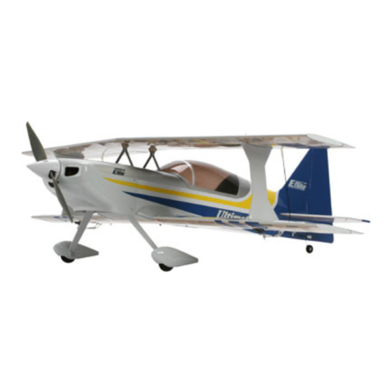
- Page 1 Ultimate 20-300 10 ARF Assembly Manual Specifications Wingspan: 38 in (960mm) Length: 41 in (1045mm) Wing Area: 473.5 sq in (30.5 sq dm) Weight w/o Battery: 34–36 oz (965–1020 g) Weight w/Battery: 39–41 oz (1105–1160 g)
-
Page 2: Table Of Contents
Table of Contents Introduction Introduction ................. 2 E-flite's Ultimate 20-300 10 ARF is a sport replica of the Using the Manual ..............2 rare two-place aerobatic aircraft. The large wing area and Contents of Kit/Parts Layout ..........3 light wing loading of its biplane design provide smooth flight Covering Colors .............. -
Page 3: Contents Of Kit/Parts Layout
7.5-gram Super Sub-Micro Digital Programmable Servo (4) EFLREX3L 3-inch Extension, Lightweight EFLREX6L 6-inch Extension, Lightweight (4) EFLREX9L 9-inch Extension, Lightweight EFLREX12L 12-inch Extension, Lightweight Covering Colors Scale White HANU973 Deep Blue HANU873 Silver HANU881 Bright Yellow HANU872 E-flite Ultimate 20-300 Assembly Manual... -
Page 4: Required Tools And Adhesives
Polymer batteries. Motor Selection Warning We recommend the E-flite Power 10 Brushless Outrunner Motor, An RC aircraft is not a toy! If misused, it can cause serious 1100Kv (EFLM4010A) for maximum performance. bodily harm and damage to property. Fly only in open areas,... -
Page 5: Warranty Information
Product. This warranty does not cover damage due to improper installation, operation, maintenance, or attempted repair by anyone other than Horizon. Return of any goods by Purchaser must be approved in writing by Horizon before shipment. E-flite Ultimate 20-300 Assembly Manual... -
Page 6: Inspection Or Repairs
Horizon Hobby. Horizon Product Support 4105 Fieldstone Road Champaign, Illinois 61822 Please call 877-504-0233 or visit horizonhobby.com to find our distributor for your country for support with any questions or concerns regarding this product or warranty. E-flite Ultimate 20-300 Assembly Manual... -
Page 7: Safety, Precautions, And Warnings
• Keep all chemicals, small parts and anything electrical out of the reach of children. • Moisture causes damage to electronics. Avoid water exposure to all equipment not specifically designed and protected for this purpose. E-flite Ultimate 20-300 Assembly Manual... - Page 8 Check that the end barely slide between the two surfaces. Doing so will of the aileron is aligned with the wing tip using a allow achieving the control throws listed with the straight edge. smallest gap possible. E-flite Ultimate 20-300 Assembly Manual...
- Page 9 8. Repeat Steps 2 through 7 for the remaining aileron on the bottom wing. 10. Once the CA has fully cured, lightly pull on each surface to make sure that each hinge has been fully saturated with CA. E-flite Ultimate 20-300 Assembly Manual...
-
Page 10: Aileron Servo Installation
Required Tools and Adhesives Medium CA Thin CA Side cutters Hobby knife Low-tack tape Pin drill Drill bit: 1/16-inch (1.5mm) Phillips screwdriver: #0, #1 Felt-tipped pen Note: The aileron control horns do not require back plates. E-flite Ultimate 20-300 Assembly Manual... - Page 11 Tie this string to the end of the servo extension as shown. Align horn to aileron centerline 3. Repeat Step 2 for the top aileron at this time. E-flite Ultimate 20-300 Assembly Manual...
- Page 12 8. Apply 2–3 drops of thin CA into each hole to harden during the servo installation. the surrounding wood. This will keep the screws secure in the holes. Install the servo using the screws provided with the servo and a #0 Phillips screwdriver. E-flite Ultimate 20-300 Assembly Manual...
- Page 13 12. Use side cutters to remove the unused arm from 10. Use a pin drill and 1/16-inch (1.5mm) drill bit the servo horn. to enlarge the hole that is 1/2-inch (13mm) from the center of the servo horn. E-flite Ultimate 20-300 Assembly Manual...
- Page 14 17. Slide the linkage through the hole in the lightweight linkage connector and attach the horn to the servo. 15. Slide a clevis retainer onto the clevis of the 2.5-inch (62mm) servo linkage. E-flite Ultimate 20-300 Assembly Manual...
-
Page 15: Stabilizer Installation
Use a 3/32-inch ball briver to tighten the socket head screws. Hint: The aileron should be centered and the servo horn aligned with the aileron hinge line before tightening the screw. 19. Repeat Steps 10 through 18 for the remaining servo linkage. E-flite Ultimate 20-300 Assembly Manual... - Page 16 4. Stand back and view the aircraft from the rear. The stabilizer must be parallel to the bottom wing. It may be necessary to lightly sand the opening in the fuselage for the stabilizer to correct this alignment. Position stabilizer parallel to bottom wing E-flite Ultimate 20-300 Assembly Manual...
- Page 17 Hint: Use a soldering iron or hot knife to cut the covering, as they will melt it and require less pressure, reducing the chances of cutting into the underlying wood. E-flite Ultimate 20-300 Assembly Manual...
- Page 18 Steps 2 through 4. Wick thin CA into the joint between the fuselage and stabilizer to glue it in position. Remember to apply CA to the top and bottom, left and right joints. E-flite Ultimate 20-300 Assembly Manual...
-
Page 19: Hinging The Rudder And Stabilizer
1. Use a felt-tipped pen to mark the center of three CA hinges. This will help in positioning them equally in the elevator and stabilizer. 3. Slide the elevator onto the elevator joiner wire. E-flite Ultimate 20-300 Assembly Manual... - Page 20 Apply thin CA to the top and bottom of each hinge. Make sure to saturate the hinges, applying the CA to the slot in the hinge so it penetrates fully into the hinge for the best bond between the stabilizer and elevator. E-flite Ultimate 20-300 Assembly Manual...
- Page 21 10. Mark four CA hinges and install them in the slots in the rudder as shown. 12. After CA is fully cured, pull on all surfaces lightly to make sure that each hinge is fully saturated and bonded. E-flite Ultimate 20-300 Assembly Manual...
-
Page 22: Rudder And Elevator Servo Installation
Install the control horn backplate on Use a 12-inch (305mm) servo extension for the rudder. the opposite side of the control horn to secure its position. Remove the covering under this also. E-flite Ultimate 20-300 Assembly Manual... - Page 23 This will keep the screws secure in the holes. Install the servo using the screws provided with the servo. 5. Install the servo arm perpendicular to the servo. E-flite Ultimate 20-300 Assembly Manual...
-
Page 24: Receiver And Landing Gear Installation
8. Repeat Steps 2 through 7 to install the rudder servo and linkage. The only difference is you will use a 12-inch (305mm) extension on the rudder servo. E-flite Ultimate 20-300 Assembly Manual... -
Page 25: Motor And Cowling Installation
1, Attach the X-mount to the motor using the screws provided with the motor and a #2 Phillips screwdriver. Note: Use threadlock on the screws to prevent them from vibrating loose. Note: Use threadlock on the screws to prevent them from vibrating loose. E-flite Ultimate 20-300 Assembly Manual... - Page 26 Note: If using the E-flite 40-amp speed control, we recommend that you tape the switch in the On position if you are not going to mount it externally. It can be...
- Page 27 6. Secure the battery inside the fuselage using the hook and loop strap. Use a piece or two of hook and loop material between the fuselage and battery to keep it from moving around in flight. E-flite Ultimate 20-300 Assembly Manual...
- Page 28 11. Attach the spinner cone to the spinner backplate using two 2mm x 8mm sheet metal screws and a #1 Phillips screwdriver. Make sure the propeller does not contact the spinner cone when it is installed. E-flite Ultimate 20-300 Assembly Manual...
-
Page 29: Upper Wing And Canopy Installation
Drill bit: 1/16-inch (1.5mm) Low-tack tape Adjustable wrench, small Canopy glue 1. Use canopy glue to attach the canopy. Use low-tack tape to keep the canopy in position until the glue has fully cured. E-flite Ultimate 20-300 Assembly Manual... - Page 30 Phillips screwdriver to attach the interplane struts to the struts. bottom wing. Install the bottom wing to the fuselage at this time. 4. Use the following image to orient the interplane struts for installation. E-flite Ultimate 20-300 Assembly Manual...
- Page 31 7. Use four 2mm x 20mm machine screws and a #1 Phillips screwdriver to secure the interplane struts to the top wing as you did on the bottom wing. E-flite Ultimate 20-300 Assembly Manual...
-
Page 32: Control Throws
Place the pushrod in the servo arm at the nearest hole to the center of the servo that will still achieve full travel of the surface without binding or running the pushrod over center. E-flite Ultimate 20-300 Assembly Manual... - Page 33 travel adjust function of radio to increase the travel of the servos to the final control throws/deflections. This will allow you to raise the travel adjust percentage in your radio to the suggested 125–135%. E-flite Ultimate 20-300 Assembly Manual...
-
Page 34: Final Control Throws
25% Expo Note: Measurements are taken at the widest point on the surface. These are general guidelines measured from our own flight tests. You can experiment with higher rates to match your preferred style of flying. E-flite Ultimate 20-300 Assembly Manual... -
Page 35: Center Of Gravity
Replace any items that would be considered questionable. Failure of any of these components in flight would mean the loss of your aircraft. After the first flights, the CG position can be adjusted for your personal preference. E-flite Ultimate 20-300 Assembly Manual... -
Page 36: Range Test Your Radio
For more information about where you can drop off your waste equipment for recycling, please contact your local city office, your household waste disposal service or where you purchased the product. E-flite Ultimate 20-300 Assembly Manual... -
Page 37: 2008 Official Ama National Model Aircraft Safety Code
Only personnel involved with flying the aircraft are allowed at or in front of the flight line. Intentional flying behind the flight line is prohibited. E-flite Ultimate 20-300 Assembly Manual... -
Page 38: Building And Flying Notes
Building and Flying Notes E-flite Ultimate 20-300 Assembly Manual... - Page 39 Building and Flying Notes E-flite Ultimate 20-300 Assembly Manual...
- Page 40 © 2008 Horizon Hobby, Inc. 4105 Fieldstone Road Champaign, Illinois 61822 (877) 504-0233 horizonhobby.com E-fliteRC.com 13465...