Icom IC-F3162DT Instruction Manual
Dpmr handheld transceiver
Hide thumbs
Also See for IC-F3162DT:
- Instruction manual (40 pages) ,
- Insrtuction manual (40 pages) ,
- Operating manual (32 pages)

Related Manuals for Icom IC-F3162DT


Summary of Contents for Icom IC-F3162DT
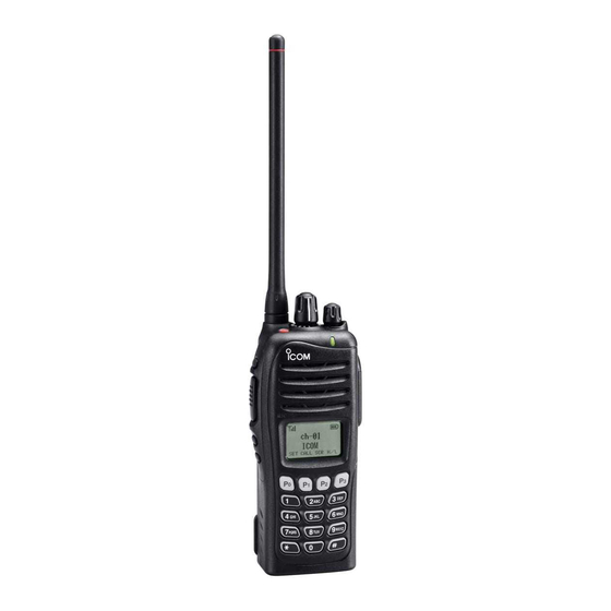
- Page 1 INSTRUCTION MANUAL VHF dPMR HANDHELD TRANSCEIVER iF3162DT iF3162DS UHF dPMR HANDHELD TRANSCEIVER iF4162DT iF4162DS The photo shows the 10-key version UHF transceiver.
-
Page 2: Explicit Defenitions
Private Mobile Radio) system operations. Ask your dealer for details. Icom, Icom Inc. and the Icom logo are registered trademarks of Icom Incor- porated (Japan) in Japan, the United States, the United Kingdom, Germany, France, Spain, Russia and/or other countries. -
Page 3: Precautions
CAUTION: NEVER * Only when the supplied battery pack, flexible antenna and connec- use non-Icom battery packs/charg- tor cover are attached. ers to prevent the loss of the transceiver’s good performance and warranty. -
Page 4: Voice Coding Technology
VOICE CODING TECHNOLOGY The AMBE+2™ voice coding Technology embodied in this product is protected by intellectual property rights including patent rights, copyrights and trade secrets of Digital Voice Systems, Inc. This voice coding Technology is licensed sole- ly for use within this Communications Equipment. The user of this Technology is explicitly prohibited from attempting to extract, remove, decompile, reverse engineer, or disassem- ble the Object Code, or in any other way convert the Object... -
Page 5: Table Of Contents
TABLE OF CONTENTS IMPORTANT ................i ■ Priority A channel selection ........18 EXPLICIT DEFENITIONS ............. i ■ Forced Narrow function ..........18 PRECAUTIONS ..............ii 4 BATTERY CHARGING ..........19–23 VOICE CODING TECHNOLOGY ........iii ■ Caution ...............19 TABLE OF CONTENTS ............iv ■... -
Page 6: Accessories
ACCESSORIES ■ Supplied accessories ■ Accessory attachments D Flexible antenna The following accessories are supplied. Connect the supplied flexible antenna Flexible antenna Battery pack Belt clip to the antenna connector. (This illustration is for the UHF type.) CAUTION: • NEVER carry the transceiver by holding only the antenna. -
Page 7: D Battery Pack
ACCESSORIES D Battery pack D Belt clip To attach the battery pack: To attach the belt clip: Slide the battery pack on the back of the transceiver in the direc- q Remove the battery pack if it is attached. tion of the arrow (q), then lock it with the battery release button. w Slide the belt clip in the direction of the arrow, until the •... -
Page 8: Accessories
ACCESSORIES D Connector cover Attach the connector cover when optional equipment is not used. To detach the connector cover: To attach the connector cover: q Remove the screw using a phillips screwdriver. q Attach the connector cover over the multi-connector. w Detach the connector cover for the optional equipment w Tighten the screw. -
Page 9: Panel Description
PANEL DESCRIPTION ■ Front panel e DEALER-PROGRAMMABLE KEY [EMR] Required functions can be programmed by your dealer. (p. 6) r DEALER-PROGRAMMABLE KEY [Side1] Speaker Required functions can be programmed by your dealer. (p. 6) t PTT SWITCH [PTT] Microphone Hold down to transmit; release to receive. Function display (p. -
Page 10: Function Display
PANEL DESCRIPTION ■ Function display o MULTI-CONNECTOR Connect an optional equipment. Connector cover NOTE: Attach the connec- tor cover when optional equipment is not used. See page 3 for details. CALA TXCU TXC q SIGNAL STRENGTH ICON !0 BUSY/TRANSMIT INDICATOR Shows relative receive signal strength level. - Page 11 PANEL DESCRIPTION y BELL ICON !0 ALPHANUMERIC DISPLAY Appears or blinks when a matching signal is received, de- ➥ Displays an operating channel number, channel name, pending on the pre-programmed settings. User Set mode contents, DTMF code, etc. ➥ Depending on the pre-programmed settings, characters u CALL CODE MEMORY ICON are displayed in 1 line or 2 lines on the LCD.
-
Page 12: Programmable Function Keys
SCAN “SCAN” function keys. ➥ Push to start or cancel a scanning operation. Consult your Icom dealer or system operator for details con- • When a scan is started by the Power ON Scan, Automatic Scan cerning your transceiver’s programming. - Page 13 PANEL DESCRIPTIONv PRIORITY A, PRIORITY B “PRA” “PRB” MEMORY CHANNELS 1, 2, 3, 4 “CH1” “CH2” “CH3” “CH4” Push to select the Priority A or Priority B channel. Push to select memory channel 1, 2, 3 or 4. PRIORITY A (REWRITE), LOCK “LOCK”...
- Page 14 PANEL DESCRIPTION TALK AROUND “TA” CALL, CALL A, CALL B “CALL” “CALA” “CALB” Push to turn the Talk Around function ON or OFF. Push to transmit a 2/5-tone code or BIIS/dPMR call. Talk Around • Call transmission is necessary before calling another station, •...
-
Page 15: Panel Description
PANEL DESCRIPTION TX CODE CHANNEL SELECT “TXC” LONE WORKER “LONE” ➥ Push to enter the TX code channel selection mode (p. 14) Push to turn the Lone Worker function ON or OFF. or the ID selection mode (BIIS, dPMR), and then push [CH •... -
Page 16: Basic Operation
BASIC OPERATION ■ Turning power ON D Battery type selection Prior to using the transceiver for the first time, the battery pack must be fully charged for optimum life and operation. The battery type must be selected, according to the attached (p. -
Page 17: Channel Selection
BASIC OPERATION ■ Channel selection D Voting operation Several types of channel selections are available. Methods The transceiver automatically starts scanning when a zone, may differ, according to your system set up. specified for the voting operation, is selected. NON-ZONE TYPE: The voting scan detects the signal strength of the repeaters, and automatically selects the strongest one. -
Page 18: Call Procedure
BASIC OPERATION ■ Call procedure ■ Receiving and transmitting When your system employs tone signalling (excluding CTCSS CAUTION: Transmitting without an antenna may damage and DTCS), a call procedure may be necessary prior to voice the transceiver. See page 1 for accessory attachments. transmission. -
Page 19: D Transmitting Notes
BASIC OPERATION D Transmitting notes D TX code channel selection • Transmit inhibit function If the transceiver has a key assigned to TX Code CH Select, The transceiver has several inhibit functions which restrict the indication can be toggled between the operating channel transmission under the following conditions: number (or name) and TX code channel number (or name). -
Page 20: D Dtmf Transmission
BASIC OPERATION D TX code edit (5-tone operation only) USING [TX CODE ENTER]: If the transceiver has a key assigned to TX Code CH Select q After pushing [TX Code CH Select], push [CH Up] or [CH or TX Code Enter, TX code contents can be edited within the Down], or push [TX Code CH Up] or [TX Code CH Down] allowable digits. -
Page 21: User Set Mode
BASIC OPERATION ■ User Set mode ■ Scrambler function The User Set mode can be accessed with the Power ON func- The Voice Scrambler function provides private communication tion. In this case, all set mode items are available. between stations. All versions have a built-in frequency inver- The User Set mode allows you to set seldom-changed set- sion type scrambler. -
Page 22: Emergency Transmission
BASIC OPERATION ■ Emergency transmission D NOTES When [Emergency] is held down for the pre-programmed time period, an emergency call is transmitted once, or repeatedly Depending on the pre-programmed settings, the following on the specified emergency channel. functions are automatically activated. * Depending on the pre-programmed settings. -
Page 23: Automatic Key Lock Function
BASIC OPERATION ■ Automatic Key Lock function ■ Forced Narrow function When the transceiver has a key assigned to Lock, the Auto- Depending on the pre-programmed settings, you can turn the- matic Key Lock function can be used. Forced Narrow function ON or OFF. When no operation occurs during the pre-programmed time When the function is ON, the channel width becomes Narrow period, the function automatically activates the Key Lock func-... -
Page 24: Battery Charging
• R DANGER! NEVER incinerate used battery packs since internal battery gas may cause them to rupture, or may • R DANGER! Use and charge only specified Icom battery cause an explosion. packs with Icom radios or Icom charger. Only Icom battery •... - Page 25 • CAUTION: NEVER charge the battery outside of the speci- You may use the battery until the remaining capacity is fied temperature range: BC-160 (0˚C to +40˚C). Icom rec- about half, then keep it safely in a cool dry place with the ommends charging the battery at +20˚C.
-
Page 26: Optional Battery Chargers
BATTERY CHARGING ■ Optional battery chargers D Regular charging with the BC-171 D Rapid charging with the BC-160 The optional BC-171 provides regular charging of the Li-Ion The optional BC-160 provides rapid charging of the Li-Ion battery pack. battery pack. Charging period: Approximately 10 hours (with BP-232N) Charging period: Approximately 3 hours (with BP-232N) The following item is additionally required:... - Page 27 BATTERY CHARGING D AD-106 installation D Rapid charging with the BC-119N+AD-106 The AD-106 must be installed into the BC- The optional BC-119N provides rapid charging of the Li-Ion charger adapter 119N/BC-121N before battery charging. battery pack. Charging period: Approximately 3 hours (with BP-232N) q Attach the plugs from the BC-119N/BC-121N to the AD- The following items are additionally required: charger adapter...
- Page 28 BATTERY CHARGING D Rapid charging with the BC-121N+AD-106 IMPORTANT: Battery charging caution The optional BC-121N allows up to 6 battery packs to be Ensure the guide tabs on the battery pack are correctly charged simultaneously. aligned with the guide rails inside the charger adapter. Charging period: Approximately 3 hours (with BP-232N) (This illustration shows the BC-160.) The following items are additionally required (purchase separately):...
-
Page 29: Battery Case
BATTERY CASE ■ Optional battery case (BP-240) When using the optional battery case attached to the trans- Fig.1 ceiver, install 6 × AAA (LR03) size alkaline batteries as illus- BP-240 trated to the right. q Unhook the battery cover release hook (q), and open the cover in the direction of the arrow (w). -
Page 30: Swivel Belt Clip
SWIVEL BELT CLIP ■ MB-93 contents r Clip the belt clip to a part of your belt. And insert the transceiver into the belt clip until the base clip inserted fully into the groove. Qty. q Belt clip ................1 w Base clip ................1 t Once the transceiver is locked in place, it swivels as illus- ■... -
Page 31: To Detach
SWIVEL BELT CLIP ■ To detach CAUTION: q Turn the transceiver upside down in the direction of the arrow and pull out from the belt clip. HOLD THE TRANSCEIVER TIGHTLY, WHEN INSERTING THE TRANSCEIVER INTO, OR DETACHING IT FROM, THE BELT CLIP. Otherwise the transceiver may not be attached to the holder or swivel properly if the transceiver is accidentally dropped and the base clip is scratched or damaged. -
Page 32: Speaker Microphone
SPEAKER MICROPHONE ■ Optional HM-169/HM-170GP ■ To attach description Attach the connector of the speaker-microphone into the multi connector on the transceiver and tighten the screw. TOP KEY GPS ANTENNA (for HM-170GP only) (for HM-170GP only) Required functions can CAUTION: Microphone be programmed by your Attach the connector of the... -
Page 33: Options
OPTIONS D BATTERY PACKS • BC-160 + BC-145S desktop charger ac adapter For rapid charging of battery pack. An AC adapter is sup- Battery pack Voltage Capacity Battery life* plied with the charger, depending on versions. 950 mAh (min.) Charging time: Approx. 3 hours when BP-232N is attached. BP-230N 7.4 V 7.35 hrs. -
Page 34: D Other Options
OPTIONS D DC CABLES • VS-1SC + HS-94/HS-95/HS-97 ptt case headset VS-1SC : VOX/PTT switch box for hands-free operation, etc. • CP-23L cigarette lighter cable HS-94 : Ear-hook type Allows charging of the battery pack through a 12 V ciga- HS-95 : Neck-arm type rette lighter socket. - Page 35 Icom transceiver. Icom is not responsible for the destruction or damage to an Icom transceiver in the event it is used with equipment that is not manufactured or approved by Icom. Some options may not be available in some countries.
-
Page 36: About Vs-1Sc Vox / Ptt Case
■ About VS-1SC vox / ptt case D VOX gain and delay adjustment The VS-1SC is a VOX/PTT unit for Icom handheld transceiv- q Attach the connector of the VS-1SC into the multi-con- ers, and allows you hands-free operation. nector on the transceiver, and tighten the screw. - Page 37 OPTIONS • VOX Delay The VOX delay time can be set to between 0.5 and 3.0 sec- onds (in 0.5 second steps). The VOX Delay is the amount of time the transmitter stays ON after you stop speaking. [Side2] VOX DLY0.5 VOX DLY3.0 Push [Side3]...
-
Page 38: Doc
IC-F3162DT/IC-F3162DS and IC-F4162DT/IC- This warning symbol indicates that this equipment F4162DS comply with the essential requirements operates in non-harmonised frequency bands and/ of the European Radio and Telecommunication or may be subject to licensing conditions in the Terminal Directive 1999/5/EC. - Page 39 • List of Country codes (ISO 3166-1) Country Codes Country Codes Austria Liechtenstein Belgium Lithuania Bulgaria Luxembourg Croatia Malta Czech Republic Netherlands Cyprus Norway Denmark Poland Estonia Portugal Finland Romania France Slovakia Germany Slovenia Greece Spain Hungary Sweden Iceland Switzerland Ireland Turkey Italy...
- Page 40 < Intended Country of Use > A-6842H-1EU Printed in Japan © 2010 Icom Inc. 1-1-32 Kamiminami, Hirano-ku, Osaka 547-0003, Japan Printed on recycled paper with soy ink.