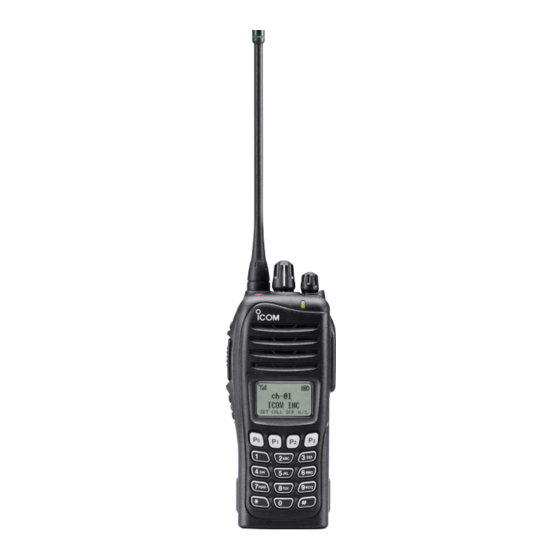
Icom IC-F3161T Instruction Manual
Vhf/uhf transceiver
Hide thumbs
Also See for IC-F3161T:
- Instruction manual (40 pages) ,
- Servise manual (48 pages) ,
- Adjustment (10 pages)
Table of Contents

Related Manuals for Icom IC-F3161T


Summary of Contents for Icom IC-F3161T
- Page 1 INSTRUCTION MANUAL VHF TRANSCEIVER iF3161T/S/DT/DS iF3163T/S UHF TRANSCEIVER iF4161T/S/DT/DS iF4163T/S This device complies with Part 15 of the FCC Rules. Operation is subject to the condition that this device does not cause harmful interference.
-
Page 2: Explicit Definitions
® and LTR system operations. Ask your dealer for details. Icom, Icom Inc. and the Icom logo are registered trademarks of Icom Incorporated (Japan) in the United States, the United Kingdom, Germany, France, Spain, Russia and/or other countries. LTR is a registered trademark of the E.F.Johnson Company. -
Page 3: Precautions
For U.S.A. only in areas with temperatures below +22°F (–30°C) or above CAUTION! Changes or modifications to this transceiver, not +140°F (+60°C). expressly approved by Icom Inc., could void your authority to operate this transceiver under FCC regulations. -
Page 4: Voice Coding Technology
FCC INFORMATION VOICE CODING TECHNOLOGY The AMBE+2™ voice coding Technology embodied in this • FOR CLASS B UNINTENTIONAL RADIATORS: product is protected by intellectual property rights including This equipment has been tested and found to comply with patent rights, copyrights and trade secrets of Digital Voice the limits for a Class B digital device, pursuant to part 15 of Systems, Inc. -
Page 5: Table Of Contents
TABLE OF CONTENTS IMPORTANT ................i ■ Scrambler function .............17 EXPLICIT DEFINITIONS ............i ■ Stun function ..............17 PRECAUTIONS ..............ii ■ Automatic Key Lock function ........17 VOICE CODING TECHNOLOGY ........iii ■ Priority A channel selection ........17 FCC INFORMATION ............iii ■... -
Page 6: Accessories
ACCESSORIES ■ Supplied accessories ■ Accessory attachments D Flexible antenna The following accessories are supplied. Connect the supplied flexible antenna to the antenna connector. Flexible Battery pack Belt clip antenna CAUTION: • NEVER HOLD the antenna when carrying the transceiver. •... -
Page 7: D Battery Pack
ACCESSORIES D Battery pack D Belt clip To attach the battery pack: To attach the belt clip: Slide the battery pack on the back of the transceiver in the direc- q Release the battery pack if it is attached. tion of the arrow (q), then lock it with the battery release button. w Slide the belt clip in the direction of the arrow until the belt •... -
Page 8: Accessories
ACCESSORIES D Connector cover Attach the connector cover when the optional equipment is not used. To detach the connector cover: To attach the connector cover: q Insert the connector cover into the multi-connector. q Unscrew the screw using a phillips screwdriver. w Detach the connector cover for the optional equipment w Tighten the screw. -
Page 9: Panel Description
PANEL DESCRIPTION ■ Front panel r DEALER-PROGRAMMABLE KEY [Side1] Desired function can be programmed by your dealer. (p. 6) t PTT SWITCH [PTT] Speaker Push and hold to transmit; release to receive. y DEALER-PROGRAMMABLE KEYS [Side2]/[Side3] Desired function can be programmed independently by Microphone your dealer. -
Page 10: Function Display
PANEL DESCRIPTION ■ Function display !0 MULTI-CONNECTOR Connect an optional equipment. Connector cover NOTE: Attach the connec- tor cover when the optional equipment is not used. See p. 3 for details. CALA TXCU TXC q SIGNAL STRENGTH INDICATOR !1 BUSY/TRANSMIT INDICATOR Indicates relative signal strength level. -
Page 11: Programmable Function Keys
[Side2], [Side3], [P0], [P1], [P2] and [P3] programmable cording to the pre-programming. function keys. Consult your Icom dealer or system operator for details con- u CALL CODE MEMORY INDICATOR cerning your transceivers programming. Appears when the call code memory is selected. - Page 12 PANEL DESCRIPTION ZONE KEY “ZONE” SCAN ADD/DEL (TAG) KEY “SCAD” Push this key, then push [CH Up] or [CH Down] to select ➥ Push to add or delete the selected channel to/from the the desired zone. When [Rotary selector] selects “operating scan group.
- Page 13 PANEL DESCRIPTION MEMORY CH 1/2/3/4 KEYS “CH1” “CH2” “CH3” “CH4” LONE WORKER KEY “LONE” Push to select the memory channels 1 to 4 directly. Push to turn the Lone Worker function ON or OFF. • If the Lone Worker function is activated, the Emergency function is automatically turned ON after the specified time period has passed MONI KEY “MON”...
- Page 14 PANEL DESCRIPTION C.TONE CH ENT KEY “TSEL” CALL KEYS “CALL” “CALA” “CALB” Push to enter the continuous tone channel selection mode. Push to transmit a 2/5-tone or BIIS ID code. Then select the desired tone frequency/code setting with [CH • Call transmission is necessary before you call another station depending on your signaling system.
- Page 15 PANEL DESCRIPTION TX CODE CHANNEL SELECT KEY “TXC” USER SET MODE KEY “SET” Push to enter the TX code channel selection mode. Then set ➥ Push and hold for 1 sec. to enter user set mode. the desired channel using [CH Up]/[CH Down]. (pgs. 14, 15) •...
-
Page 16: Basic Operation
BASIC OPERATION ■ Turning power ON D Battery type selection Prior to using the transceiver for the first time, the battery pack must be fully charged for optimum life and operation. The battery type must be selected according to the attaching (p. -
Page 17: Channel Selection
BASIC OPERATION ■ Channel selection AUTOMATIC SCAN TYPE: Several types of channel selections are available. Methods may differ according to your system set up. Channel setting is not necessary for this type. When turning power ON, the transceiver automatically starts scanning. NON-ZONE TYPE: Scanning stops when receiving a call. -
Page 18: Call Procedure
BASIC OPERATION ■ Call procedure ■ Receiving and transmitting When your system employs tone signalling (excluding NOTE: Transmitting without an antenna may damage the CTCSS and DTCS), this call procedure may be necessary transceiver. See (p. 1) for accessory attachments. prior to voice transmission. -
Page 19: D Transmitting Notes
BASIC OPERATION D Transmitting notes D TX code channel selection • Transmit inhibit function If the transceiver has [TX Code CH Select] assigned to it, The transceiver has several inhibit functions which restrict the indication can be toggled between the operating channel transmission under the following conditions: number (or name) and TX code channel number (or name). -
Page 20: D Dtmf Transmission
BASIC OPERATION D TX code number edit USING [TX CODE ENTER] KEY: (PMR operation only) q After pushing [TX Code CH Select], push [CH Up] or [CH If the transceiver has [TX Code CH Select] or [TX Code Down], Enter] assigned to it, TX code contents can be edited within or push [TX Code CH Up] or [TX Code CH Down] to select the allowable digits. -
Page 21: User Set Mode
BASIC OPERATION ■ User set mode ■ Emergency transmission User set mode is accessed at power ON and allows you to When [Emergency] is pushed for the specified time period, set seldom-changed settings. You can “customize” the trans- an emergency signal is automatically transmitted. (p. 9) ceiver operation to suit your preferences and operating style. -
Page 22: Scrambler Function
BASIC OPERATION ■ Scrambler function ■ Priority A channel selection The voice scrambler function provides private communication When one of the following operations is performed, the trans- between stations. All versions have a built-in frequency inver- ceiver selects the Priority A channel automatically. sion type scrambler;... -
Page 23: Battery Charging
• R DANGER! Use and charge only specified Icom battery • R DANGER! DO NOT expose the battery to rain, snow, packs with Icom radios or Icom charger. Only Icom battery seawater, or any other liquids. - Page 24 If • R DANGER! NEVER charge the battery pack in areas with any of these conditions occur, contact your Icom dealer or extremely high temperatures, such as near fires or stoves, distributor.
-
Page 25: Optional Battery Chargers
BATTERY CHARGING ■ Optional battery chargers D Regular charging with the BC-171 D Rapid charging with the BC-160 The optional BC-171 provides regular charging of the Li-Ion The optional BC-160 provides rapid charging of the Li-Ion battery pack. Charging period: Approx. 10 hours (with BP- battery pack. - Page 26 BATTERY CHARGING D AD-106 installation D Rapid charging with the BC-119N+AD-106 The AD-106 must be installed into the The optional BC-119N provides rapid charging of the Li-Ion charger adapter BC-119N or BC-121N before battery charging. battery pack. Charging period: Approx. 3 hours (with BP- ➥...
- Page 27 BATTERY CHARGING D Rapid charging with the BC-121N+AD-106 IMPORTANT: Battery charging caution Ensure the guide lobes on the battery pack are correctly The optional BC-121N allows up to 6 battery packs to be aligned with the guide rails inside the charger adapter. charged simultaneously.
-
Page 28: Battery Case
BATTERY CASE ■ Optional battery case (BP-240) When using the optional battery case attached to the trans- Fig.1 ceiver, install 6 × AAA (LR03) size alkaline batteries as illus- BP-240 trated at right. q Unhook the battery cover release hook (q), and open the cover in the direction of the arrow (w). -
Page 29: Swivel Belt Clip
SWIVEL BELT CLIP ■ MB-93 contents e Clip the belt clip to a part of your belt. And insert the transceiver into the belt clip until the base clip inserted fully into the groove. Qty. q Belt clip ................1 w Base clip ................1 r Once the transceiver is locked in place, it swivels as illus- ■... -
Page 30: To Detach
SWIVEL BELT CLIP ■ To detach q Turn the transceiver upside down in the direction of the CAUTION: arrow and pull out from the belt clip. HOLD THE TRANSCEIVER TIGHTLY, WHEN HANGING OR DETACHING THE TRANSCEIVER FROM THE BELT CLIP. Otherwise the transceiver may not be attached to the holder or swivel properly if the transceiver is accidentally dropped and the base clip is scratched or damaged. -
Page 31: Speaker Microphone
SPEAKER MICROPHONE ■ Optional HM-169/170GP ■ To attach description Attach the connector of the speaker-microphone into the multi connector on the transceiver and tighten the screw. TOP KEY GPS ANTENNA (for HM-170GP only) CAUTION: (for HM-170GP only) Attach Desired functions can multi connector snugly, but Microphone be programmed by... -
Page 32: Options
OPTIONS D BATTERY PACKS • BC-171 + BC-147 desktop charger ac adapter For regular charging of battery packs. We recommend that Battery pack Voltage Capacity Battery life* the BP-230N charging. An AC adapter is supplied with the 950 mAh (min.) charger depending on versions. - Page 33 OPTIONS D DC CABLES D ANTENNAS • CP-17L • FA-SC56VS/FA-SC57VS/FA-SC73US cigarette lighter cable stubby antennas Allows charging of the battery pack through a 12 V ciga- Shorter VHF or UHF antennas. rette lighter socket. (For BC-119N) FA-SC56VS: Frequency range 150–162 MHz •...
- Page 34 D About VS-1SC ptt case VOX gain and delay adjustment The VS-1SC is a VOX/PTT unit for Icom handheld transceiv- ers, and allows you hands-free operation. q Attach the connector of the VS-1SC into the multi-con- nector on the transceiver and tighten the screw.
- Page 35 OPTIONS • VOX Delay The VOX delay time can be set from 0.5 to 3.0 sec. (0.5 sec. step) for a convenient interval before returning to receive. [Side2] VOX DLY0.5 VOX DLY3.0 Push [Side3] SET TXCU TXC CALA SET TXCU TXC CALA 0.5 sec (min.) 3.0 sec (max.)
-
Page 36: Safety Training Information
• ALWAYS keep the antenna at least 2.5 cm (1 inch) away sure to Radio Frequency Electromagnetic Fields, 3 kHz to from the body when transmitting and only use the Icom belt- 300 GHz. clips listed on page 27 when attaching the radio to your belt, •... - Page 37 SAFETY TRAINING INFORMATION Electromagnetic Interference/Compatibility During transmissions, your Icom radio generates RF energy that can possibly cause interference with other devices or systems. To avoid such interference, turn off the radio in areas where signs are posted to do so. DO NOT operate the transmitter in areas that are sensitive to electromagnetic radiation such as hospitals, aircraft, and blasting sites.
- Page 38 MEMO...
- Page 39 MEMO...
- Page 40 A-6638H-1EX-w Printed in Japan © 2007–2009 Icom Inc. 1-1-32 Kamiminami, Hirano-ku, Osaka 547-0003, Japan Printed on recycled paper with soy ink.