Table of Contents
Advertisement
Quick Links
Advertisement
Table of Contents

Related Manuals for Martin Audio DX0.5

Summary of Contents for Martin Audio DX0.5
- Page 1 MARTIN AUDIO DX0.5 USER GUIDE DX0.5 LOUDSPEAKER MANAGEMENT SYSTEM ...
-
Page 2: Table Of Contents
DX0.5 USER GUIDE DX0.5 Contents DX0.5 ........................................ 1 Important Safety Instructions ................................ 5 Introduction ...................................... 7 Features ...................................... 7 How to Use This Manual ................................... 7 Getting Started .................................... 7 Things to Remember: ................................... 8 Hook‐up Diagrams .................................... 9 Passive Full‐Range Loudspeakers .............................. 9 Passive Main Loudspeakers with Subwoofers and Delays ...................... 10 ... - Page 3 DX0.5 USER GUIDE Delay Units .................................... 17 Ramps on changes .................................. 18 Software Version .................................. 18 Preset Utilities .................................... 18 Recall a Preset .................................. 18 Save a Preset................................... 18 Delete a Preset .................................. 19 Security Utilities .................................. 19 Show Parameter .................................. 19 Lock Unit .................................... 19 User Password .................................. 19 Enable Password .................................. 20 ...
- Page 4 DX0.5 USER GUIDE Repair ...................................... 29 Audio Connections .................................. 30 XLR Connectors ................................... 30 XLR ...................................... 30 Control Application .................................. 31 Connect Device ................................... 31 Linking ...................................... 32 Program Utility ................................... 33 Open Preset from PC ................................ 33 Save Preset to PC .................................. 33 Store Preset to Device ................................ 34 ...
- Page 5 DX0.5 USER GUIDE Fader Adjustment ................................... 56 Direct value ..................................... 56 Delay ...................................... 57 Delay Adjustment ................................... 58 Inverse Polarity .................................. 58 Technical Specifications .................................. 59 Warranty ...................................... 60 Technical Drawing .................................. 61 HAM09224 User Guide V1.0 ...
-
Page 6: Dx0.5
DX0.5 USER GUIDE Important Safety Instructions 1. Read these instructions. 2. Keep these instructions. 3. Heed all warnings. 4. Follow all instructions. 5. Do not use this apparatus near water. 6. Clean only with a dry cloth. 7. Do not block any ventilation openings. Install in accordance with the manufacturer’s instructions. 8. Do not install near any heat sources such as radiators, heat registers, stoves, or other apparatus (including amplifiers) that produce heat. 9. Do not defeat the safety purpose of the polarized or grounding‐type mains plug. A polarized plug has two blades with one wider than the other. A grounding‐type plug has two blades and a third grounding prong. The wide blade or the third prong are provided for your safety. If the provided plug does not fit into your outlet, consult an electrician for replacement of the obsolete outlet. 10. Protect the power lead from being walked on or pinched particularly at plugs, convenience receptacles, and the point where they exit from the apparatus. 11. Only use attachments/accessories specified by the manufacturer. 12. Use only with a cart, stand, tripod, bracket, or table specified by the manufacturer, or sold with the apparatus. When a cart is used, use caution when moving the cart/apparatus combination to avoid injury from tip‐over. 13. Unplug this apparatus during lightning storms or when unused for long periods of time. 14. Refer all servicing to qualified service personnel. Servicing is required when the apparatus has been damaged in any way, such as power supply cable or plug is damaged, liquid has been spilled or objects have fallen into the apparatus, the apparatus has been exposed to rain or moisture, does not operate normally, or has been dropped. 15. This apparatus shall not be exposed to dripping or splashing, and no object filled with liquids, such as vases or beer glasses, shall be placed on the apparatus. 16. Do not overload wall outlets and extension leads as this can result in a risk of fire or electric shock. 17. This apparatus has been designed with Class‐I construction and must be connected to a mains socket outlet with a protective earthing connection (the third grounding prong). 18. This apparatus has been equipped with a rocker‐style AC mains power switch. This switch is located on the rear panel and should remain readily accessible to the user. ... - Page 7 DX0.5 USER GUIDE The exclamation point within an equilateral triangle is intended to alert the user of the presence of important operating and maintenance (servicing) instructions in the literature accompanying the appliance. 19. The MAINS plug or an appliance coupler is used as the disconnect device, so the disconnect device shall remain readily ...
-
Page 8: Introduction
authority, or your household waste disposal service. Introduction Offering sophisticated EQ, crossover, dynamics processing and system protection, the Martin Audio DX0.5 Loudspeaker Management System provides complete system optimization for both passive and powered systems. Five different operating modes cover a wide range of systems. Each of the six outputs feature dedicated level control, mute, polarity invert, high / low‐ pass filters, 7‐band parametric / shelving EQ, 600ms delay and limiting. Two input channels provide independent level control, mute, 600ms delay and a flexible 5‐band parametric / shelving EQ. The convenient front‐panel control also includes 7‐segment LED metering per channel. The DX0.5 utilizes high‐end 24‐bit AKM® AD/DA converters with 120 dB dynamic range for class‐... -
Page 9: Things To Remember
DX0.5 have been set. 10. Start the signal source and raise the mixer’s main L/R fader(s) up until audio is heard through the loudspeakers. At this point the system is tested and working however we strongly encourage that you read the rest of this owner’s manual to learn basic navigation, how to edit the inputs and outputs, set security features and more. Things to Remember: Never listen to loud music for prolonged periods. Please see the Safety Instructions on page 6 for information on hearing protection. When you shut down the equipment, turn off the amplifiers first to prevent thumps and other noises generated by any upstream equipment from coming out of the speakers. When powering up, turn on the amplifiers last. Save the shipping boxes and packing materials, in the unlikely event of a problem with the DX0.5 these may be required to ship the device to an authorised Service Agent. HAM09224 User Guide V1.0 8 ... -
Page 10: Hook-Up Diagrams
DX0.5 USER GUIDE Hook‐up Diagrams Passive Full‐Range Loudspeakers In this example, the DX0.5 is configured using the ‘3xStereo’ setup type. The left and right line‐level XLR outputs from a mixer feed the A and B XLR inputs of a DX0.5 Loudspeaker Management system. XLR outputs 1 and 2 of the DX0.5 system feed the 1 and 2 XLR inputs of a Martin Audio MA3.0 Power Amplifier. The CH 1 and CH 2 NL4 speaker outputs of the power amplifier feed the Phoenix inputs of two Martin Audio CDD12 passive loudspeakers located either side of the venue stage. XLR outputs 3 and 4 of the DX0.5 feed the 1 and 2 XLR inputs of a Martin Audio MA2.0 Power Amplifier. The CH 1 and CH 2 NL4 speaker outputs of this power amplifier feed the Phoenix inputs of two Martin Audio CDD8 passive loudspeakers. These are positioned halfway toward the rear of the venue and have delay added, so they are time aligned with the CDD12s using the output delay available on the DX0.5. Finally XLR outputs 5 and 6 of the DX0.5 feed the 1 and 2 XLR inputs of another Martin Audio MA2.0 Power Amplifier. The CH 1 and CH 2 NL4 speaker outputs of this power amplifier feed the Phoenix inputs of two Martin Audio CDD6 passive loudspeakers which are located in a separate area away from the coverage of the main system. HAM09224 User Guide V1.0 9 ... -
Page 11: Passive Main Loudspeakers With Subwoofers And Delays
In this example, the DX0.5 is configured using the ‘2xStereo+Subs’ setup type. The example here is how the system for the nightclub section of the CDD launch event was configured. The left and right line‐level XLR outputs from a mixer feed the A and B XLR inputs of the DX0.5. XLR outputs 1 and 2 of the DX0.5 feed the 1 and 2 XLR inputs of a Martin Audio MA5.2K Power Amplifier. The CH 1 and CH 2 NL4 speaker outputs of the power amplifier feed the Phoenix inputs of two Martin Audio CDD15 ... -
Page 12: Bi-Amped Full-Range Loudspeakers With Subwoofers
DX0.5 USER GUIDE Bi‐amped Full‐Range Loudspeakers with Subwoofers In this example, the DX0.5 is configured using the ‘2x2Way+Subs’ setup type. The left and right line‐level outputs from a mixer feed the A and B XLR inputs of a Martin Audio DX0.5 Loudspeaker Management system. XLR outputs 1 and 2 of the DX0.5 feed the 1 and 2 XLR inputs of a Martin Audio MA2.0 Power Amplifier. The CH 1 and CH 2 NL4 speaker outputs of the power amplifier feed the high frequency inputs of two Martin Audio bi‐amped Blackline H3+. XLR outputs 3 and 4 of the DX0.5 feed the 1 and 2 XLR inputs of another Martin Audio MA3.0 Power Amplifier. The CH 1 and CH 2 NL4 speaker outputs of this power amplifier feed the low frequency inputs of the H3+. This requires a four‐core speaker cable to go to the H3+, at the amplifiers this needs to be split so the low frequency feed on pins 1+/‐ is fed from the MA3.0 and the mid/high feed on pins 2+/‐ is fed from the MA2.0. XLR outputs 5 and 6 of the DX0.5 feed the 1 and 2 XLR inputs of a Martin Audio MA9.6K Power Amplifier. The CH 1 and CH 2 NL4 speaker outputs of this power amplifier feed the NL4 input of S18+ subwoofers. The DX0.5’s high‐ and low‐pass filters on the output channels are configured to create a crossover so that outputs 1 and 2 of the DX0.5 deliver the high frequencies to the loudspeakers, outputs 3 and 4 deliver the low frequencies to the same loudspeakers and outputs 5 and 6 deliver the sub frequencies to the passive subwoofers. The subs may be stereo or mono by properly ... -
Page 13: Powered Main Loudspeakers And Subwoofers With Separate Stereo Full-Range Loudspeakers
Powered Main Loudspeakers and Subwoofers with Separate Stereo Full‐Range Loudspeakers The Martin Audio DX0.5 Loudspeaker Management system is also useful for controlling powered loudspeakers and subwoofers. Here, the DX0.5 is configured using the ‘2xStereo+Subs’ setup type. The left and right line‐level XLR outputs from a mixer feed the A and B XLR inputs of the DX0.5. XLR outputs 1 and 2 of the DX0.5 feed the XLR inputs of two Martin Audio DD12 powered loudspeakers. These loudspeakers are located on stage. XLR outputs 3 and 4 of the DX0.5 feed the XLR inputs of another two Martin Audio DD12s. This full‐range pair should be positioned halfway toward the rear of the venue with delay added so they are time‐aligned with the main pair. Finally, XLR outputs 5 and 6 of the DX0.5 feed the XLR inputs of two Martin Audio PSX powered subwoofers that are located on stage and paired with the DD12 loudspeakers. In this setup, the DX0.5’s high‐ and low‐pass filters on outputs 1 and 2 and 5 and 6 may be used to configure a crossover between the DD12 and PSX for added control from the processor. Care should be taken when configuring the DX0.5’s crossover so the PSX built‐in crossover does not conflict. The subs may be stereo or mono by properly configuring the input sources for DX0.5 outputs 5 and 6. The DX0.5 may be used for additional room corrective EQ and delay to align the loudspeakers and subwoofers and a limiter added for extra protection against over powering from irresponsible DJs for example. HAM09224 User Guide V1.0 12 ... -
Page 14: Powered Arrayable Loudspeakers And Subwoofers
USER GUIDE Powered Arrayable Loudspeakers and Subwoofers Here, the DX0.5 is configured using the ‘2xStereo+Subs’ setup type. The left and right line‐level XLR outputs of a mixer feed the A and B XLR inputs of the DX0.5 Loudspeaker Management system. XLR outputs 1, 2, 3 and 4 of the DX0.5 feed the XLR inputs of a pair of MA3.0 amplifiers. The CH 1 and CH 2 NL4 speaker outputs of these power amplifiers feed the Phoenix inputs of the top and bottom of a stereo pair of 16 module Omniline arrays XLR output 5 of the DX0.5 is connected to the A & B XLR main inputs of a Martin Audio MA5.2K; it is only necessary to connect a cable to input A as the amplifier has a link switch to parallel both inputs. The CH 1 and CH 2 NL4 speaker outputs of this power amplifier feed the Phoenix input of a pair of CSX212 passive subwoofers The DX0.5’s high‐ and low‐pass filters on output channels 1–5 may be configured to create a crossover to optimize the subwoofers with the Omniline. The subs are run mono by properly configuring the input sources for DX0.5 output 5. The DX0.5 may be used for adding the PEQ recommended by the Omniline software and any additional room corrective EQ. Delay to align the loudspeakers and subwoofers can be added and a limiter for protection of the system. HAM09224 User Guide V1.0 13 ... -
Page 15: Dx0.5 2X6 Loudspeaker Management System Features: Rear Panel
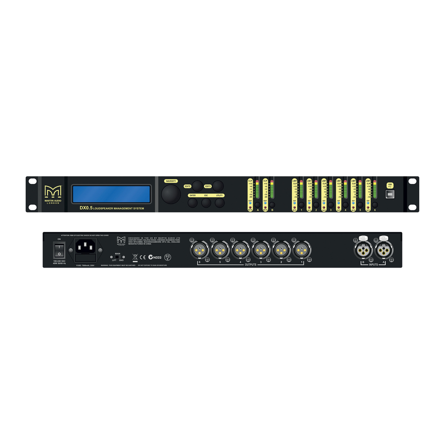
2. Power Lead Socket and Fuse This is where to connect the detachable power cable included with the processor. Plug the other end of the power lead into an AC outlet. The outlet should match the power cable. WARNING: Bypassing the plug’s safety ground pin can be dangerous. Don’t do it! The fuse is located behind the fuse cover, at the bottom of the IEC socket. See the “Troubleshooting” section on page 22 for information about replacing the fuse. 3. Main: Lift / Gnd The ground lift separates the chassis ground from the signal ground. The default position is GND. You may attempt to remedy system ground loop hum by moving the switch to LIFT. 4. XLR Outputs These six male XLR connectors provide a balanced line‐level signal for each of the processor’s output channels. Connect these to the inputs of power amplifiers and/or powered loudspeakers. 5. XLR Inputs These female XLR connectors accept a balanced line‐level input from a mixer or other source main L/R output. DX0.5 2x6 Loudspeaker Management system Features: Front Panel 6. LCD Display The LCD Display is one of the most vital features of the processor. It displays processor information including (but not limited to) System, Preset and Security Utilities, gain, delay, EQ and other input and output processing parameters. When the DX0.5 is powered up, the last state it was in will load up and the LCD Display will present the current system setup type: 2xStereo+Sub [default] 2x2Way+Sub 2x3Way 3xStereo 1x6Way ... -
Page 16: Edit2 Control
DX0.5 USER GUIDE The Nav/Edit1 rotary encoder control allows you to navigate the user interface, edit sections of the processor, navigate within screens to select sub‐menus, pages and parameters, as well as select values during editing. 8. Edit2 Control The Edit2 rotary encoder control allows you to edit parameters, as well as select values during editing. 9. Edit3 Control The Edit3 rotary encoder control also allows you to edit parameters, as well as select values during editing. In general, use the Nav/Edit1 rotary encoder control to scroll through the various pages and configuration settings. Depending on the page, individual parameters may be changed by turning one (or more) of the encoders. In some cases, the Edit2 and Edit3 controls provide fine and course control of the same parameter. 10. Enter Button The Enter Button allows you to dig deeper and deeper into menus and parameters, confirm operations and change settings. 11. ESC Button The ESC Button allows you to retreat from selected variables. In some cases, it confirm operations and changes settings, as well. These will be noted. 12. Utility Button Press this button to select and update the DX0.5’s utilities. There are three main utilities menus: System Utilities Preset Utilities Security Utilities Within each, an array of sub‐menus are available. 13. Mute / Edit Buttons These eight buttons serve a dual purpose: Muting selected inputs and outputs Editing selected inputs and outputs ... -
Page 17: Usb
These meters should remain green with the occasional peak into the yellow zone. If the level stays constantly in the yellow section (or any red clipping), lower the level of the source until feeding the DX0.5 until the metering returns to occasional ... -
Page 18: System Utilities
DX0.5 USER GUIDE Press the ESC button [11] to return to the main screen. Press the Enter Button [10] to enter and edit the selected Utilities menu. This is how we reach the sub‐menus of the Utilities. System Utilities Turn the Nav/Edit1 Control until System Utilities is presented and press the Enter Button [10] to reach the System Utilities sub‐ menus as listed below: System Setup Delay Units Ramps on changes Software Version Looking at each of these sub‐menus individually;‐ The Nav/Edit1 Control [7] is used to navigate between the four System Utilities. The ESC button [11] is used to return to the System Utilities menu. The Enter Button [10] is used to enter and edit the chosen System Utility. Press the Enter Button [10] to enter System Setup. System Setup System Setup is where the processor is configured for your particular loudspeaker system. It configures channel names, input routing to outputs and provides starting points for crossover setups. The five options are listed below. Here, turn the Edit2 [8] or Edit3 [9] Control to scroll between the different System Setup ... -
Page 19: Software Version
DX0.5 USER GUIDE Turn the Edit2 [8] or Edit3 [9] Control to scroll between these three choices. Press the Enter Button [10] once a unit of delay has been decided. The processor will return to the Delay Units splash screen. Or press the ESC button [11] to return to the System Utility menu without making any changes. Ramps on changes When engaged, sudden volume changes may be avoided when changing parameter values, particularly when using a Windows‐ based PC to control the unit. Disengage this feature for live applications since instant response to change is desired. Turn the Edit2 [8] or Edit3 [9] Control to scroll between Ramps : On and Ramps : Off [default]. If changing, press the Enter Button [10] only once here. The processor will return to the Ramps on changes splash screen. Or press the ESC button [11] to return to the System Utility menu without making any changes. Software Version Nothing may be edited on this page. Press the Enter Button [10] to view what version of software is installed in this DX0.5. Press the Enter [10] or ESC [11] Button to return to the Software Version splash screen. Preset Utilities This is where to save, recall and delete presets on the DX0.5. This is useful when the PA system has multiple setups for different environments or several loudspeaker systems utilizing varying setups. Note: As mentioned earlier, the DX0.5 will load up the last state it was in when it was powered down. As mentioned earlier, the way to get here from the main menu is by pressing the Utility Button [12]. Once inside the Utility Menu, scroll the Nav/Edit1 Control [7] clockwise to Preset Utilities. Now press the Enter Button [10] again to reach the sub‐menus as listed below: Recall a Preset Save a Preset Delete a Preset ... -
Page 20: Security Utilities
DX0.5 USER GUIDE Delete a Preset If a preset is no longer needed for recall, it may be deleted here. It will help to keep the DX0.5’s memory clutter‐free. Turn the Edit2 [8] or Edit3 [9] Control to scroll between presets 1 – 24. Press the Enter Button [10] once you have selected the preset to delete. Press the Enter Button [10] twice: once to select and again to confirm. The processor will return to the Delete a Preset splash screen. Security Utilities This is where to lock the DX0.5 to prevent anyone from accidentally (or intentionally) changing the settings. You also have control over some of the system behaviour after it’s been locked. As discussed earlier, the way to get here from the main menu is by pressing the Utility Button [12]. Once inside the Utility Menu, scroll the Nav/Edit1 Control [7] clockwise to Security Utilities. Now press the Enter Button [10] again to reach the sub‐menus as listed below. Show Parameter Lock Unit User Password Enable Password The Nav/Edit1 Control [7] is used to navigate between the four Security Utilities. The ESC button [11] is used to return to the Security Utilities menu. The Enter Button [10] is used to enter and edit the chosen Security Utility. Press the Enter Button [10] to enter Show Parameter. Show Parameter Once a DX0.5 has been locked, you have the option of allowing the various processing parameter values to be shown or not. Turn the Edit2 [8] or Edit3 [9] Control to scroll between Parameter will be shown [default] and Parameter will not be shown. If changing, press the Enter Button [10] only once here. The processor will return to the Show Parameter ... - Page 21 DX0.5 USER GUIDE Wrong! and the processor will return to the If the entered password is wrong, the splash screen will display Password User Password splash screen without changing the password. The password has been updated, but it is still disabled. This leads us to the fourth – and final – sub‐menu: Enable Password Here is where the user password is enabled. The Nav/Edit1 Control [7] moves the cursor left and right while the Edit2 [8] and Edit3 [9] Controls change the text. Enter the correct password and press the Enter Button [10]. Turn the Edit2 [8] or Edit3 [9] Control to scroll between Password : Disable [default] and Password : Enable. If changing, press the Enter Button [10] only once here. When enabling, a symbol resembling a padlock will appear in the lower‐right area of the LCD Display [6]. Pressing the Utility Button [12] here returns you directly to the User Password splash screen. When disabling, the padlock symbol disappears and the processor will return to the Security Utilities splash screen. The password will need to be entered to make any changes once the DX0.5 has been locked and password enabled. Therefore, make a note of the password and keep it somewhere safe. If the password is lost, you will have to perform a factory reset to restore the unit’s default settings [see page 13]. HAM09224 User Guide V1.0 20 ...
-
Page 22: Editing
The input gain allows you to adjust the entire system levels up and down. This is where to compensate for variations in the signal level of the program material from your signal source Press the Enter button [10] to enter and edit the gain. An arrow –> will appear next to Gain indicating that it is ready to be edited. Use the Edit2 [8] or Edit3 [9] Controls to change the gain by ±0.1 dB per click. Turning these Controls clockwise increases gain, while turning them anticlockwise decreases gain. The gain ranges from –15.0 dB to +15.0 dB. Press the ESC button [11] to exit the gain editing mode. Delay Setting up input delays on the DX0.5 is useful for time aligning components of a system either to each other or to the live instruments or both. Press the Enter button [10] to enter and edit the delay. An arrow –> will appear next to Delay indicating that it is ready to be edited. As stated on page 14, Delay may be represented in one of three ways: Time(ms), or Distance(m) [default], or ... -
Page 23: Outputs 1-6
DX0.5 USER GUIDE ±0.0208 ms per click, or ±0.007 m per click, or ±0.023 feet per click Turning these Controls clockwise increases the delay time, while turning them anticlockwise decreases the delay time. The minimum and maximum delay ranges from: 0.0000 ms – 600.9984 ms 0.000 m – 204.339 m 0.000 feet – 670.233 feet Press the ESC button [11] to disengage Editing. EQ Bypass EQ Bypass flattens the 5‐Band EQ on the input so you may hear exactly how it is affecting the system. By toggling the EQ Bypass on and off, you may quickly compare the sound with and without EQ. Turn the Edit2 [8] or Edit3 [9] Control to scroll between Bypass = Off [default] and Bypass = On. Press the ESC button [11] to accept the new EQ Bypass mode and exit the EQ Bypass editing mode. 5‐Band EQ Editing input EQ on the DX0.5 is useful for adjusting the response of the entire PA, particularly when correcting anomalies caused by venue acoustics. It is standard practice to use the input EQ for this function leaving the output EQ for any cabinet EQ ... -
Page 24: 7-Band Eq
DX0.5 USER GUIDE EQ Bypass 7‐Band EQ Delay High Pass Filter Low Pass Filter Limiter VU Meter The Nav/Edit1 Control [7] is used to navigate between Name, Source, Polarity, Gain, EQ Bypass, 7‐Band EQ, Delay, High Pass Filter, Low Pass Filter, Limiter and the VU Meter. The ESC button [11] is used to disengage Editing and return to the previous menu. Press the Enter Button [10] to enter Name. An arrow –> will appear next to Name indicating that it is ready to be edited. The aforementioned arrow –> will appear next to whatever setting is ready to be edited: Name, Source, Polarity, Gain, EQ Bypass, 7‐Band EQ, Delay, High Pass Filter, Low Pass Filter, Limiter and the VU Meter. Name Here is where the name of the selected output(s) may be changed. The Nav/Edit1 Control [7] moves the cursor left and right while the Edit2 [8] and Edit3 [9] Controls change the text. Press the Enter button [10] to accept the new name and return to the Edit menu. Pressing the ESC button leaves the name unchanged and returns you to the output edit menu. Source There are three input sources to choose between: InA = Input A ... - Page 25 DX0.5 USER GUIDE EQ Bypass flattens the 7‐Band EQ on the output so you may hear exactly how it is affecting the system. By toggling the EQ Bypass on and off, you may quickly compare the sound with and without EQ. Turn the Edit2 [8] or Edit3 [9] Control to scroll between Bypass = Off [default] and Bypass = On. Press the ESC button [11] to accept the new EQ Bypass mode and exit the EQ Bypass editing mode. 7‐Band EQ Output EQ is used primarily for adjusting the response of a particular loudspeaker or transducer. Additionally, output EQ may be used to correct room anomalies in multi‐room setups. Use the Nav/Edit1 [7] Control to change the frequency. Turning this Control clockwise increases the frequency, while turning it anti‐clockwise decreases the frequency. The frequency ranges from 20.0 Hz to 20.0 kHz. Use the Edit2 [8] Control to change the bandwidth by ±0.05 per click. Turning this Control clockwise increases the bandwidth, while turning it anticlockwise decreases the bandwidth. The EQ band may be configured as high or low shelf by turning it all the way anti‐clockwise. These are the EQ choices from the furthest anticlockwise option to the furthest clockwise option: –12 High Shelving –6 High Shelving –12 Low Shelving –6 Low Shelving 0.05 – 3.00 [Parametric] To change the EQ between shelving and parametric, the gain must first be set to 0.0 dB. Use the Edit3 [9] Control to change the gain by ±0.5 dB per click. Turning this Control clockwise increases the gain, while turning ...
-
Page 26: High Pass Filter
DX0.5 USER GUIDE 0.000 m – 204.339 m 0.000 feet – 670.233 feet Press the ESC button [11] to exit delay editing mode. High Pass Filter High Pass Filters are utilized to set up crossovers in multi‐way loudspeaker and subwoofer systems. They may also be used to roll‐off low frequencies that full‐range loudspeakers cannot efficiently reproduce. Use the Edit2 [8] Control to change the frequency. Turning this control clockwise increases the frequency, while turning it anti‐ clockwise decreases the frequency. The frequency ranges from 20.0 Hz to 20.0 kHz. Turn the Edit3 [9] Control to see the various filter type and slope options: No Cut‐Off Butterworth 6 dB Butterworth 12 dB Linkwitz‐Riley 12 dB Bessel 12 dB Butterworth 18 dB Butterworth 24 dB Linkwitz‐Riley 24 dB Bessel 24 dB ... -
Page 27: Vu Meter
DX0.5 USER GUIDE Attack Release Threshold Use the Nav/Edit1 Control [7] to change the attack time. Turning this Control clockwise increases the attack time, while turning it anti‐clockwise decreases the attack time. The attack time ranges from 5ms to 200ms. The attack time increment depends on where it is currently set: 5 ms – 20 ms: ±1 ms per click 20 ms – 30 ms: ±5 ms per click 30 ms – 100 ms: ±10 ms per click 100 ms – 200 ms: ±20 ms per click Use the Edit2 Control [8] to change the release time by ±0.1 s per click. Turning this control clockwise increases the release time, while turning it anti‐clockwise decreases the release time. The release time ranges from 0.1 s to 3.0 s. Use the Edit3 Control [9] to change the threshold by ±0.2 dBu per click. Turning this Control clockwise increases the threshold, while turning it anticlockwise decreases the threshold. The threshold ranges from –10.0 dBu to +20.0 dBu. A setting of +20.0 dBu is off. Press the ESC button [11] to exit limiter editing mode. VU Meter You may choose between viewing the signal level or the limiter’s gain reduction for each output. These will be displayed on the 7‐segment LED meters [16]. Turn the Edit2 [8] or Edit3 [9] Control to scroll between VU-Meter = Level [default] and VU-Meter = Limiter Act. If the latter is selected, the Clip LED on the selected output(s) will illuminate to indicate 0 dB of gain reduction. When the ... -
Page 28: Service Information
DX0.5 USER GUIDE Service Information If you think your Martin Audio product has a problem, please check out the following troubleshooting tips to confirm the problem. Visit the Support section of our website (www.Martin Audio.com) to contact our technical support team. You may find the answer to the problem without having to return your Martin Audio DX0.5 for servicing. Troubleshooting No Power Is it plugged in? Make sure the power cord is securely seated in the IEC socket and plugged all the way into the AC outlet. ... -
Page 29: Bad Sound
DX0.5 USER GUIDE Are the level controls set the same for both sides on the mixer, amplifier and processor? Are the gain settings the same for all left‐right pairs of inputs and outputs on the processor? Are the EQ settings the same for all left‐right pairs of inputs and outputs on the processor? Are the limiter settings the same for all left‐right pairs of outputs on the processor? Check the pan control on the signal source. It may be turned too far to one side. If you’re using a stereo signal source, it may be delivering an out‐of‐balance stereo signal. Try switching sides: Turn off the amp, swap the speaker cables at the amp and turn the amp back on. If the same side is still louder, the problem is with your speaker cabling or the loudspeakers. If the other side is louder now, the ... -
Page 30: Repair
DX0.5 USER GUIDE Repair For warranty service, refer to the warranty information on page 28. Non‐warranty service for Martin Audio products is available from Martin Audio Distribution Partner of Dealer. To locate your nearest DP or Dealer, visit www.Martin‐Audio.com, click “Contact” and select “Worldwide Distributors” If you do not have access to our website, you can call our Product Support Team on +44 (0)1494 535312, Monday‐Friday during normal business hours to explain the problem. Tech Support help to identify whether it is a configuration or other problem rather than a product failure but if the DX0.5 does need to be returned they will help identify the nearest Dealer to your area. HAM09224 User Guide V1.0 29 ... -
Page 31: Audio Connections
DX0.5 USER GUIDE Audio Connections XLR Connectors The DX0.5 has two female XLR input jacks that accept balanced line‐level signals. When connecting a balanced signal, be sure it’s wired per AES (Audio Engineering Society) standards: XLR Pin 1 – Shield (Ground) Pin 2 – Hot (+) Pin 3 – Cold (–) You should use high‐quality, shielded cable to connect the signal source to the input sockets on the DX0.5. High quality microphone cables work well. Foil shielded cables are commonly used for audio wiring in installed systems. The better the shield, the better the immunity from externally induced noise (like EMI and RFI). Route the cable away from AC power cords and outlets. These are common sources for hum in an audio signal. Additionally, there are six male XLR output jacks on the DX0.5. These are also wired according to the AES standards listed above. HAM09224 User Guide V1.0 30 ... -
Page 32: Control Application
DX0.5 USER GUIDE Control Application The DX0.5’s Control Application provides you with a simple, intuitive means of programming the device using your USB‐equipped Windows‐based PC. All of the System Setup, Preset, Utilities and Editing functions detailed in this user guide are available via the software, plus a few more which are detailed below. To get started, simply visit www.Martin Audio.com, navigate "Support" and select "software" from the drop‐down menu. Download the driver and software installers and follow the installation instructions. Once you’ve successfully installed the driver and software and connected your DX0.5, simply launch the DX0.5 application. The software will auto‐detect and connect to the DX0.5, after which you can begin programming in real time. Or if you prefer to work offline, you can configure a system via the software, save your work as a preset, and later connect to the DX0.5 and load your settings into it. When the DX0.5 is connected and controlled by the software application, all front panel controls on the unit are disabled and the LCD screen indicates that the unit is locked. Launching the application for the first time will take you to the Utilities screen;‐ This window is divided into four sections where you can manage program, system, security and, options. At the bottom of the ... -
Page 33: Linking
DX0.5 USER GUIDE It will change to show it is connecting;‐ And a window will appear showing that the application is searching the available COM ports for a connected DX0.5;‐ Once connected the button will change to 'Disconnect Device' giving you the option to work off line without closing the application;‐ Linking The top right section shows the linking option for input and output channels;‐ ... -
Page 34: Program Utility
DX0.5 USER GUIDE Program Utility This section manages the saving and recalling of presets between your PC and the DX0.5. Open Preset from PC Clicking on this button will highlight it blue;‐ A window will open allowing you to navigate to the location on your PC where you have saved preset files which will have a .mdx suffix. Select the file you wish to load and click 'Open' and the preset will be shown in a window for you to confirm the ... -
Page 35: Store Preset To Device
DX0.5 USER GUIDE A window will open allowing you to navigate to a suitable location to store your file. You can add a file name of your choice then click 'Save' to store the file for future use;‐ Store Preset to Device The DX0.5 has 24 Preset locations into which your choice of presets can be stored. As supplied the first 13 locations will have CDD presets and you can chose to store new configurations to any of the eleven empty locations, or over‐write the CDD presets. Note that you can easily download the CDD presets from the Martin Audio website if they have been over‐written and you wish to restore the factory settings. Once you have defined all the parameters in your project click on 'Store Preset to Device';‐ A window will open showing all 24 preset locations;‐ HAM09224 User Guide V1.0 34 ... -
Page 36: Recall Preset From Device
DX0.5 USER GUIDE You can select the desired preset location into which you wish to store your file either by clicking on the preset in the main part of the window, or by clicking on 'Select preset number' and choosing the desired location from the drop‐down list. In the 'Edit preset name' section you can give you preset a name of your choice up to 16 characters. If you are over‐writing an existing preset and want to keep the same name you can double click on it in the preset list and the name will be transferred to the Edit preset name section. Once you are happy with the preset location and name click 'Store' and a window will appear asking you to confirm;‐ If you are happy to proceed click 'Yes' and the preset will be stored in the designated location. Recall Preset from Device ... - Page 37 DX0.5 USER GUIDE Click 'Yes' to proceed, the selected preset will be loaded. If off line this will be almost instantaneous, if connected to a DX0.5 you will see a progress bar at the top of the window which will take a few seconds to travel from left to right as the preset is loded. HAM09224 User Guide V1.0 36 ...
-
Page 38: System Utility
DX0.5 USER GUIDE System Utility System Setup This button opens a window in which the system architecture can be configured;‐ The options are;‐ 2xStereo+Sub, a twin stereo system with mono sub feeds, suitable for a stereo system with a pair of passive mid top cabinets each side with additional subs which are few from a mono sub of the stereo input. 2x2Way+Sub is a stereo system using bi‐amp cabinets for mid‐top also with mono sub outputs. 2x3Way is a stereo system with either tri‐amped speakers each side or possibly bi‐amp mid top cabinets with independent subs also run in stereo. 1x6Way is a mono system with six independent full range outputs. Inputs A and B can be used and a mono signal is derived from both of them. When you have selected your desired configuration, click on the 'Confirm' button. You will see a pop‐up window;‐ HAM09224 User Guide V1.0 37 ... -
Page 39: Ramp Audio On Changes
DX0.5 USER GUIDE If you are happy to proceed select 'Yes' and the system routing will change accordingly. Ramp Audio on changes This feature when enabled prevents sudden changes in the audio which could be undesirable if adjustments are being made with audio passed through the processor. Regardless of how big a change is made to a parameter such as gain the level will ramp slowly from the previous setting to the new so there is no sudden jump in volume. This would usually only be necessary during programming as in the majority of cases changes that are selected in a live environment will need to change as quickly as possible Version info This button brings up a Window with the DX0.5 software version details; Click 'OK' to close the window HAM09224 User Guide V1.0 38 ... -
Page 40: Security Utility
DX0.5 USER GUIDE Security Utility This section features a number of facilities to protect the DX0.5 from unauthorised operation, particularly when used with an installed system. Show parameters when locked This feature when enabled allows a user to navigate through all settings when a DX0.5 is locked to see the values et cetera but without allowing any changes to be made. For complete lock‐out leave this un‐checked which will prevent even looking through the parameters. Change Password This allows the user to change the stored password for a new one. Click on the button and the following window appears;‐ Type the correct password, the default for a new DX0.5 is 000000. You will see the following window;‐ HAM09224 User Guide V1.0 39 ... -
Page 41: Lock Unit
DX0.5 USER GUIDE You can now enter a password of your choice which can be from 1 to six digits. Re‐enter the new password to confirm and click 'OK' and your password is now stored. Lock Unit With lock Unit activated no parameters can be adjusted or viewed unless the Show parameters when locked feature has been enabled. This applies to the software application and to the DX0.5 once disconnected from your PC. It can be unlocked with a second click on the Lock Unit button. Lock Unit Password This function operates in the same way as Lock unit only requiring your security password to be entered to lock and unlock the DX0.5 for additional security. Click on the button and a window will pop‐up requesting your password;‐ Enter the password, either your own if you have changed the password to one of your choice via the Change Password feature, or the default which is 000000. The Unit is now locked both to changes in the software and to the DX0.5 itself once disconnected from your PC. To unlock, click the button a second time and the same Password window appears. Re‐enter your password and the DX0.5 is unlocked. HAM09224 User Guide V1.0 40 ... -
Page 42: Options Utility
DX0.5 USER GUIDE Options Utility This section features functions for the configuration of the input and output channels. Copy Input This allows you to copy all parameters from channel A to B or B to A. A click on the button brings up the following window;‐ Select which input either A or B is the source from which you wish to copy the parameters, then select the destination input whichever is not the same as the source. Click 'Confirm and all parameters will be copied across match both inputs. Note that you can use the Link function to keep both inputs completely matched in real time whichever parameters are adjusted. Copy Output Copy output works in exactly the same way as copy input with the difference that there are six outputs from which to select your source and destination channels. Clicking the 'Copy Output' button opens the following window;‐ HAM09224 User Guide V1.0 41 ... -
Page 43: Edit Channel Names
DX0.5 USER GUIDE Operation is the same as copying inputs; click in the Output Source drop‐down to select which of the six output channels you would like to copy then click on the Destination drop‐down to select which output you would like to copy the parameters to. Click 'Confirm' and all parameters are copied across. Note that as with inputs, any outputs can be linked together to keep all parameters matched. Edit Channel names This option allows you to change the default output channel names to something suited to your application. Click on the button to bring up the name editing window;‐ Click on any of the output names in the column on the right and type a new name which can be up to six characters in length. HAM09224 User Guide V1.0 42 ... -
Page 44: Gain/Mute/Lim
DX0.5 USER GUIDE Gain/Mute/Lim The first and possibly most important tab is the Gain, mute and limiter page;‐ From this page you can view the input and output levels, adjust gain, mute channels and set limiter parameters. Gain Gain is adjustable for both inputs and all six outputs using either the gain fader which can be dragged and dropped to any value required or alternatively specific values can be typed into the Gain value window. Input gain can be adjusted from ‐15 to +15dB. Output gain from ‐12dB to +6dB. The faders default to the zero position therefore are in a slightly different vertical position due to the different scales. Here are am input and output fader for comparison;‐ HAM09224 User Guide V1.0 43 ... -
Page 45: Metering
DX0.5 USER GUIDE Mute is available on all input and output channels via the Mute button just to the right of the fader and below the VU meter. In normal, un‐muted mode the button is grey, when activated the channel is muted and the button turns red. Here are both un‐ muted and muted versions;‐ Metering Both input and output channels feature multi‐segment bargraph‐style VU Meters which have a scale from ‐20dBu to +18dBu with a clip segment right at the top. The output meters also feature a limit light above the bargraph to indicate limiter operation. In addition there is an option in the Limiter section change the output VU Meter function to indicate limiter activity. This changes the scale to read from ‐30 to ‐2 dB. Here are input and output VU meters plus and output meter configured to show limiter activity;‐ Limiters Limiters are available to protect the speaker system connected to each output;‐ These have fully adjustable controls for the Threshold; the level in dBu at which the limiter will activate. This can be adjusted from ‐10 to 20dBu. 20dBu is the default which is essentially out of circuit. Values can be adjusted up and down using the two arrowed buttons or specific values typed directly into the window. Attack time is the time in milliseconds before which the limiter will operate; a shorter time acts like a clip limiter stopping virtually all signals from exceeding the threshold level, a slower time will allow short‐term peaks to pass through whilst still restricting the long term power keeping it to within levels at which the drivers will avoid damage. As with threshold the values can be cycled up HAM09224 User Guide V1.0 44 ... - Page 46 DX0.5 USER GUIDE and down using the arrowed buttons or values can be entered by directly typing them into the window. Values can range from 5ms up to 200. Steps are 1ms from 5 to 20ms, 5ms from 20 to 30ms, 10ms from 30 to 100ms then 20ms from 100 to 200. Release is the time in seconds that it takes the gain to return to normal after levels drop back below the limiter threshold. A slower release helps to make the limiter less audible reducing the "pumping" sound that is often audible. As with threshold and attack the values can be cycled up and down using the arrowed buttons or values can be entered by directly typing them into the window. Values can range from 0.1s up to 3s in steps of 0.1seconds. HAM09224 User Guide V1.0 45 ...
-
Page 47: Routing
DX0.5 USER GUIDE Routing The routing tab allows you to configure the routing from the two input channels to the six output;‐ This page also allows quick access to the pages for other adjustments;‐ Clicking on any other the input or output boxes will bring up the output naming window. Clicking on any of the Gain or Limiter boxes will open the Gain/Mute/Lim tab. Clicking on a Polarity or Delay box will take you to the Delay Tab. Clicking on PEQ or X‐over will open the input or output channel tab depending on which box is clicked. The routing from inputs A and B will be pre‐determined by your choice of system configuration but can be freely modified to suit your requirements by simply clicking on the nodes to show a tick. Not that all outputs must have at least one input routed, they cannot be left un‐routed (but can of course be muted if you don't need to use a channel). Both nodes can be clicked to run the output channel from a mono signal derived from both input channels;‐ HAM09224 User Guide V1.0 46 ... - Page 48 DX0.5 USER GUIDE Finally the mute commands for all inputs and output are repeated on this page to mute or unmute channels are required when configuring a controller. HAM09224 User Guide V1.0 47 ...
-
Page 49: Input Channel
DX0.5 USER GUIDE Input channel Both input channels have 5 bands of equalisation available which is configured in this window. The graph in the main section of the window shows a representation of the frequency response of the filtering applied with the red trace for channel A, blue for channel B. The position of the five filters is represented by the circled numbers with the one highlighted in green being the currently selected filter. The response for the selected filter is shown with a dashed yellow trace;‐ The section at the top of the page is where the filters to be adjusted can be selected;‐ Filters 1 to 5 are shown on the left with a thumbnail of a PEQ filter, the selected filter will be highlighted in green. Over to the right are A and B buttons to select which of the two input channels are to be configured. EQ in inputs can be completely ... - Page 50 DX0.5 USER GUIDE To the right side of the window are the dedicated Property controls for the selected filter;‐ The channel that you have selected is shown at the top of this section;‐ The specific filter selected from PEQ1 to 5 is shown just under this;‐ HAM09224 User Guide V1.0 49 ...
- Page 51 DX0.5 USER GUIDE Next are two buttons to bypass or reset all filters;‐ 'Bypass ALL' will return the signal path to a flat response but retains the filter slopes you are created. A second click will put the EQ back in place. 'FLAT' as the name suggests resets the gain of all filters to 0dB. Frequency and Q factor values are retained but any gain settings are lost. Note that previous values cannot be restored unless you have stored your settings as a Preset, they will have to be manually re‐entered. The next features is the EQ type which offers a drop‐down with the filter types available;‐ All filters are Bell by default but may be configured as High Shelf with either a 6 or 12dB per octave slope, or Low Shelf, also with 6 or 12dB per octave slopes. Finally there are three fader controls to adjust the parameters of each filter; Gain, Frequency and Quality factor, or if high or low shelf filters are selected Gain and Frequency;‐ HAM09224 User Guide V1.0 50 ...
-
Page 52: Adjusting Filters
DX0.5 USER GUIDE Each fader shows the precise numerical value corresponding to the fader position. The Quality factor has an additional value window showing the equivalent Bandwidth in octaves corresponding to the Q factor that has been set, this is useful for some third party speaker brands who specify their equalisation using bandwidth. Adjusting filters Filters can be adjusted in no less than four ways either from the graph screen or using the dedicated filter control. Gain is adjustable between +/‐ 15dB, frequency from 20Hz to 20kHz and Q from 0.4 to 128. Click and Hold Click and hold on any of the Filter numbers in the graph. This will instantly select that filter it can then be dragged to any position ... -
Page 53: Output Channel
DX0.5 USER GUIDE Output Channel The output channel Tab opens the window where all equalisation for output channels is controlled, it is very similar to the input Window;‐ The graph as with the input window displays the frequency response for the output selected. These are colour coded so you can easily identify which output you are viewing. Colours are as follows;‐ Out 1 = Purple Out 2 = Pink Out 3 = Blue Out 4 = Green Out 5 = Brown Out 6 = Orange All output channels have seven bands of parametric equalisation available plus high and lowpass filters. These are shown in the graph as either their number from 1 to 7 or "LP" for low pass or "HP" for highpass enclosed in a circle. The currently selected filter will be highlighted green and that filters response shown with a dashed yellow trace;‐ ... - Page 54 DX0.5 USER GUIDE The top section of the window is where filters and outputs are selected;‐ Parametric filters 1 to 7 are selected using the buttons on the left followed by the high pass and low pass filters. Over to the right are buttons 1 to 6 to select which of the output channels you are controlling. As with inputs, all outputs can be configured completely independently unless you have used the link function to link two or more channels together. The final button is the 'Show All' which displays the response of all six channels;‐ To the right side of the window is the Property window which will look different depending on which filter or filter type is ...
- Page 55 DX0.5 USER GUIDE At the top of all types you will see the channel name, this will be the default "Out 1, out 2…." Unless you have edited the name in which case the new name will be displayed;‐ Next the filter type is displayed, either PEQ (parametric) 1 to 7, Highpass or Low Pass;‐ Next are two buttons to bypass or reset all filters;‐ 'Bypass ALL' will return the signal path to a flat response but retains the filter slopes you are created. A second click will put the EQ back in place. 'FLAT' as the name suggests resets the gain of all filters to 0dB. Frequency and Q factor values are retained but any gain settings are lost. Note that previous values cannot be restored unless you have stored your settings as a Preset, they will have to be manually re‐entered. The next features is the EQ type which offers a drop‐down with the filter types available;‐ All filters are Bell by default but may be configured as High Shelf with either a 6 or 12dB per octave slope, or Low Shelf, also with 6 or 12dB per octave slopes. For high and low pass filters the slope is available for selection from the flowing options;‐ No cut‐off (bypassed) 6dB per octave Butterworth 12dB per octave Butterworth 12dB per octave Linkwitz Riley 12dB per octave Bessel 18dB per octave Butterworth ...
-
Page 56: Adjusting Filters
DX0.5 USER GUIDE 24dB per octave Linkwitz Riley 24dB per octave Bessel Finally there are three fader controls to adjust the parameters of each filter; Gain, Frequency and Quality factor, or if high or low shelf filters are selected Gain and Frequency or just Frequency for High and low pass filters;‐ Each fader shows the precise numerical value corresponding to the fader position. The Quality factor has an additional value window showing the equivalent Bandwidth in octaves corresponding to the Q factor that has been set, this is useful for some third party speaker brands who specify their equalisation using bandwidth. Adjusting filters Filters can be adjusted in no less than four ways either from the graph screen or using the dedicated filter control. Gain is ... -
Page 57: Fader Adjustment
DX0.5 USER GUIDE All adjustments available in the graph are shown using a right click on the prompt at the bottom of the graph;‐ Right clicking brings up the following window which explains the keyboard shortcuts available to control filters;‐ Fader Adjustment All filter parameter values can be adjusted by clicking and dragging the faders for either gain, frequency or Q. The value box at the top of each fader will update to show the exact value and the graph will update to show the frequently response. Direct value Precise values for gain, frequency and Q can be typed directly into the value box at the top of each fader. Note that values for frequency have to be entered in full, the software does not recognise 'K' for values in thousands so for example if you need a value of 2.5 kHz it is necessary to enter "2500". HAM09224 User Guide V1.0 56 ... -
Page 58: Delay
DX0.5 USER GUIDE Delay The final tab is delay which is where input and output delay can be added to time align either an entire system or components within a cabinet. At the top of the window is a selection option for how the delay is specified, either by time in milliseconds, distance in meters or distance in feet for counties using imperial measurements;‐ The diagram then shows inputs A and B with delay adjustment available for both channels independently (unless they have been linked);‐ Routing is shown with red (for channel A) and blue (for channel B) lines going from their respective input channels directly to the output channels to which they have been routed;‐ HAM09224 User Guide V1.0 57 ... -
Page 59: Delay Adjustment
DX0.5 USER GUIDE Finally the output channels are shown with individually adjustable delay for each channel plus polarity adjustment;‐ Delay Adjustment Delay is adjusted for input and output channels in exactly the same way using the adjustment buttons either left to decrease delay or right to increase. Delay is adjustable from zero to a maximum of 600ms / 204 metres / 669 feet. There are course and fine adjustment buttons available. The course adjustment increases or decreases in increments of 1ms / 0.34 metres / 1.114 feet. Fine adjustments increases or decreases delay in increments of 0.0206ms / 0.006 metres / 0.022 feet. Precise values can also be directly typed into the value box. Inverse Polarity Clicking the Inverse polarity button inverts the output channel adding a 180°pase shift The output channel names are also displayed and clicking on any of these is another option to open the name editing window. HAM09224 User Guide V1.0 58 ... -
Page 60: Technical Specifications
DX0.5 USER GUIDE Technical Specifications INPUTS 2 electronically balanced analogue CMRR >58dB OUTPUTS 6 electronically balanced analogue MAX OUTPUT +21dBu FREQUENCY RESPONSE 20Hz‐20kHz ± 0.2dB DYNAMIC. RANGE 120dB DISTORTION < .004% 20Hz‐20kHz MAXIMUM DELAY >600 ms MIN STEP SIZE 20 μS INPUT GAIN ... -
Page 61: Warranty
DX0.5 USER GUIDE Warranty Martin Audio DX1.5 Loudspeaker Management Systems are warranted against manufacturing defects in materials or craftsmanship over a period of 1 year from the date of original purchase. During the warranty period Martin Audio will, at its discretion, either repair or replace products which prove to be defective provided that the product is returned in its original packaging, shipping prepaid, to an authorised Martin Audio service agent or distributor. Martin Audio Ltd. cannot be held responsible for defects caused by unauthorised modifications, improper use, negligence, ... -
Page 62: Technical Drawing
DX0.5 USER GUIDE Technical Drawing HAM09224 User Guide V1.0 61 ...