Table of Contents
Advertisement
Quick Links
Advertisement
Table of Contents

Related Manuals for E-FLITE Brio 10 ARF


Summary of Contents for E-FLITE Brio 10 ARF
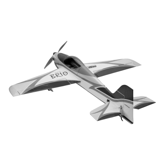
- Page 1 Brio 10 ARF Assembly Manual...
-
Page 2: Table Of Contents
Table of Contents Contents of Kit/Parts Layout .........3 Landing Gear Installation ........11 Introduction ............4 Aileron Hinging ..........15 Specifications ............4 Aileron Servos and Linkages ......18 Required Radio Equipment ........4 Wing Installation ..........21 Important Information About Motor Selection ..5 Stabilizer, Elevator & Rudder ......23 Quique Somenzini’s Lightweight 3D Power Setup ...5 Firewall Installation ...........28 High Speed Precision Outrunner Setup ....5... -
Page 3: Contents Of Kit/Parts Layout
Pull-Pull Control Horn EFL2285 Wing Tube EFLA200 Micro Control Horns EFLA202 Micro Tail Skid EFLA203 Micro Control Connectors EFLA213 E-flite/JR/Horizon Decals EFLA214 Micro Pull-Pull Set EFLA271 Spinner, 1 " Black EFLA221 Foam Park Wheels, 1.5" EFLM1915 Outrunner Stick Mount EFLM1916... -
Page 4: Introduction
Introduction Required Radio Equipment Thank you for purchasing the E-flite ™ Brio 10 ARF. If You will need a minimum 6-channel transmitter (for proper anybody knows what precision feels like, 3-time World mixing capabilities), crystal, and four sub-micro servos. Champion and 2-time US Champion Quique Somenzini You can choose to purchase a complete radio system that certainly does. -
Page 5: Important Information About Motor Selection
Proper throttle management is required to (EFLM1505). For high-speed F3A flying only, we recommend achieve optimum performance and prevent E-flite’s Power 10 BL Outrunner motor (EFLM4010A). This shortened battery life. setup will weigh about 3 ounces more than the lightweight alternative. -
Page 6: High Power 6-Pole Setup (Using Gearbox)
Other Possible Setups Required Tools and Adhesives Optional High Speed Precision Outrunner Setup Tools & Equipment EFLM4010A Power 10 Brushless Outrunner Motor, EFLA257 Screwdriver, #0 Phillips (or included with 1100Kv EFLA250) EFLA312B 40-Amp Brushless ESC (V2) EFLA251 Hex Wrench: 3/32" (or included with APC12060E Electric Propeller, 12 x 6E EFLA250) -
Page 7: Using The Manual
Using the Manual Before Starting Assembly This manual is divided into sections to help make assembly Before beginning the assembly of your Brio 10, remove easier to understand, and to provide breaks between each each part from its bag for inspection. Closely inspect the major section. -
Page 8: Safety Precautions
Safety Precautions Questions or Assistance This is a sophisticated hobby product and not a toy. It must For questions or assistance, please direct your email to be operated with caution and common sense and requires productsupport@horizonhobby.com, or call 877.504.0233 some basic mechanical ability. Failure to operate this product toll free to speak to a service technician. -
Page 9: Limited Warranty & Limits Of Liability
Limited Warranty & Limits of Liability Pursuant to this Limited Warranty, Horizon Hobby, Inc. REPAIR OR REPLACEMENT AS PROVIDED UNDER will, at its option, (i) repair or (ii) replace, any product THIS WARRANTY IS THE EXCLUSIVE REMEDY OF determined by Horizon Hobby, Inc. to be defective. In the THE CONSUMER. -
Page 10: Warranty Inspection And Repairs
Warranty Inspection and Repairs Non-Warranty Repairs To receive warranty service, you must include your original Should your repair not be covered by warranty and the sales receipt verifying the proof-of-purchase date. Providing expense exceeds 50% of the retail purchase cost, you will be warranty conditions have been met, your product will be provided with an estimate advising you of your options. -
Page 11: Landing Gear Installation
Landing Gear Installation 1. Use a hobby knife with a new blade to remove the covering from the fuselage where the landing Required Parts gear will be inserted. • Fuselage • Main landing gear (L&R) • Tail skid • Wheel pant (L&R) •... - Page 12 2. Slide the landing gear into the fuselage. The 3. Slide the 2mm x 25mm bolt through the holes in the gear will only line up when installed landing gear. Secure the bolt using a 2mm nut correctly. Slide a #4 washer onto each of the four and threadlock.
- Page 13 4. Thread a 2mm nut 1/8" (3mm) from the first 5. Slide the wheel pant into position and nut. Use threadlock or thin CA to keep the nut secure it using the 2mm x 8mm wood screw. from rotating.
- Page 14 8. Use Medium CA to glue the tail skid into position. 6. Repeat Steps 4 through 6 for the remaining wheel and wheel pant. 7. Drill two 1/8" (3mm) holes in the tail for the tail skid.
-
Page 15: Aileron Hinging
Aileron Hinging 1. Locate the positions for the hinges. Drill a 1/16" (2mm) hole in the center of each slot of Required Parts both the wing and aileron. This creates a tunnel • Wing (left and right) for the CA, allowing the CA to penetrate into the •... - Page 16 2. Slide three hinges into the slits in the aileron. 3. Slide the aileron into position. Check to Center the slot in the hinge with the hole drilled make sure it can move without interference at in Step 1.
- Page 17 4. Firmly grasp the wing and aileron and gently pull on the aileron to ensure the hinges are secure and cannot be pulled apart. Use caution when gripping the wing and aileron to avoid crushing the structure. 5.
-
Page 18: Aileron Servos And Linkages
Aileron Servos and Linkages 2. Attach a 6" servo extension to the aileron servo. Secure the extension using string or a Required Parts commercially available clip. • Wing panel (right and left) • Micro control connector (2) • 2mm x 4mm screw (2) •... - Page 19 3. Place the servo in the wing. Guide the servo 4. Attach the 3" (75mm) pushrod to the control lead out through the opening at the wing root. horn. Start the wire from the wing tip side of the Secure the aileron servo using the screws control horn.
- Page 20 6. Turn on the radio system and center the 5. Attach the micro control connector to a long aileron trim and stick. Make sure the aileron servo 3D servo arm. Be sure to use the included is operating properly using the transmitter. Slide retainer to secure the micro control connector the pushrod wire through the micro connector.
-
Page 21: Wing Installation
Wing Installation 2. Remove the hatch from the fuselage. Slide the wing panel with tube into position on Required Parts the fuselage. • Fuselage • Wing (right and left) • Wing tube • #4 washer (2) • 4-40 x 1/2" socket head screw (2) Required Tools and Adhesives •... - Page 22 3. Slide a #4 washer onto a 4-40 x 1/2" socket head screw. Slide the remaining wing panel into position. Secure the panels using 4-40 x 1/2" socket head screws with #4 washers (silver) using a 3/32" hex wrench.
-
Page 23: Stabilizer, Elevator & Rudder
Stabilizer, Elevator & Rudder 2. Cut the rear of the fuselage using a hobby knife to allow the stabilizer to be slid into the fuselage. Required Parts • Fuselage w/wing installed • Stabilizer • Rudder • Elevator • CA hinge (9) Required Tools and Adhesives •... - Page 24 3. Position the stabilizer into the slot in 4. Measure from the stab tip to the wing tip. Adjust the aft end of the fuselage. Slide the stabilizer the stab until the measurements are equal. as far forward as possible. Center the stabilizer in the slot in the fuselage.
- Page 25 5. View the airframe from the rear and make sure the wing and stab are parallel. If not, lightly sand the stab saddle until they are. 6. Double-check the adjustments from Steps 1 through 3. Use a felt-tipped pen to trace the outline of the fuselage onto the top and bottom of the stabilizer.
- Page 26 8. Slide the stab and elevator back into position. 7. Use a sharp hobby knife to cut the covering Again, check the alignment and make sure slightly inside the lines drawn. Be very careful everything lines up. Wick Thin CA into the not to cut into the underlying wood, as this will joint between the fuselage and stabilizer.
- Page 27 9. Install the four carbon rods between the fuselage 10. Attach the rudder using three CA hinges. Use and stabilizer as shown. Glue the rods to the the technique as described in Aileron Hinging for stabilizer and fuselage using 6-minute epoxy. this procedure.
-
Page 28: Firewall Installation
Firewall Installation Required Parts • Fuselage • Power 10 Outrunner Firewall • Inrunner/Park 480 Outrunner Firewall Required Tools and Adhesives • 6-minute epoxy 1. The Brio has two firewall options. One is identified as the Inrunner/Park 480 Outrunner Firewall. The second is identified as Power 10 Outrunner Firewall. - Page 29 2. Attach the firewall to the sub-firewall structure on the front of the fuselage nose at this time using 6-minute epoxy or thick CA. Epoxy is best for this application. Make sure all joints are secure when finished so the firewall does not detach from the sub-firewall.
-
Page 30: Park 480 Outrunner Motor Installation
Park 480 Outrunner Motor Installation 1. Secure the firewall stick mount to the fuselage using four 4-40 x 1/2" socket head screws. Required Parts • Fuselage • Firewall stick mount (included) • 4-40 x 1/2" (12mm) socket head screw (4) •... - Page 31 2. Attach the outrunner motor to the outrunner 3. First, cut 3/16" inches (5mm) off the end of motor mount using the included spacers (4) and the included Firewall Stick Mount so the motor 3mm x 8mm screws (4). properly clears the cowling.
-
Page 32: Power 10 Outrunner Motor Installation
Power 10 Outrunner Motor Installation 1. Attached the aluminum X-mount to the back of your motor with the flat head machine screws Required Parts included with your motor. • Fuselage • Outrunner offset mounts, 32mm (4) • 4-40 x 43mm socket head screws (4) •... - Page 33 2. Using four 4-40 x 43mm socket head screws and washers and outrunner offset spacers, attach the motor with X-mount to the blind nuts on the firewall The offset spacers have already been sized correctly so you have proper clearance when the cowling is installed later.
-
Page 34: 6-Pole Motor Installation
Note: It is very important that the gear mesh • 4-40 x 1/2" (12mm) socket head screw (4) is set correctly and is smooth with no binding. • Firewall stick mount The E-flite ™ gearbox features adjustable slotted • 6-Pole motor •... - Page 35 2. Attach the motor to the gearbox using the screws 3. Attach the firewall stick mount to the firewall provided with the motor and blue threadlock. using four 4-40 x 1/2" socket head screws. Hint: The gearbox is in two pieces. Apply a bead of medium CA where the two pieces join to stiffen the mount for extreme aerobatics.
-
Page 36: Cowling, Esc And Propeller Installation
Cowling, ESC and Propeller Installation 4. Slide the gearbox into position on the motor mount. Use a 1/16" (1.5mm) drill to drill a hole Required Parts on each side of the gearbox and into the mount. • Fuselage Stagger the holes so the screws will not interfere •... - Page 37 Some 35A–40A brushless ESC on the market Our E-flite 40A Brushless ESC (V2) (EFLA312B) either warn against running four (4) sub-micro is equipped with a higher rated, heavy-duty servos or do not specify this setup will work. BEC that can dissipate more heat and handle...
- Page 38 1. Connect the ESC to the motor and secure the 3. Attach the cowling using four 3mm x 8mm sheet ESC to the inside of the fuselage using hook and metal screws. loop material and/or a tie wrap. The location of the ESC may be changed depending on the length of the motor wires, type of ESC and necessity to move the ESC to achieve the correct...
- Page 39 Outrunner motor. to ream a larger opening into the backplate of Skip to Step 7 for the installation of your E-flite ™ spinner to fit the shaft size of the the propeller when using an Inrunner motor prop adapter shaft.
- Page 40 Note: Two spacers have been provided that Note: It is very important that you check to be are placed between the propeller and spinner sure the propeller is balanced before installing backplate. Use the thin spacer for low-pitch onto the shaft. An unbalanced propeller will propellers, the thick spacer for high-pitch cause performance issues.
- Page 41 7. Insert the 'hex to round' adapter onto the shaft. 8. Slide the propeller onto the gearbox shaft. Slide Then, slide the 6mm washer included with your the spacer included with the spinner onto the gearbox onto the output shaft. gearbox shaft in front of the prop as needed.
- Page 42 9. Slide the spinner backplate onto the gearbox 10. Snap the spinner cone onto the shaft. Secure the propeller and spinner backplate spinner backplate. using a 4mm washer and 4mm locknut. Make sure not to over-tighten the 4mm locknut.
-
Page 43: Rudder And Elevator Servos
Rudder and Elevator Servos 1. Secure a 12" (305 mm) servo extension to one of the servos. Mount the elevator servo in the aft end Required Parts of the fuselage using the hardware provided with • Fuselage the servo. Secure the extension using string or a •... - Page 44 2. Attach the micro control horn to the elevator 3. Install the micro control connector onto the using a micro control horn backplate. Apply a elevator servo arm. Pass the elevator pushrod few drops of medium CA to the backplate. wire through the connector.
- Page 45 Note: An optional rudder servo location has At this time, we suggest that you trial fit the been provided at the rear of the fuselage if battery and receiver into the front of the using heavier motors and you choose not to use fuselage and follow the steps outlined on page the pull-pull system.
- Page 46 4. Lightly sand both sides of the middle section of 5. Mount the rudder servo inside the fuselage using the plastic rudder control horn before installing so the hardware provided with the servo. Install the CA wicks better. Install the rudder control horn two micro control connectors into a long servo for the rudder using medium CA.
- Page 47 6. Use tape to hold the rudder in neutral. Slide a 7. Slide the micro cable adjust connector into cable crimp onto the control cable. The cable the micro control connector and use a 2mm x then goes through the horn, then back through 3mm screw to hold it in position.
- Page 48 8. The cables will cross inside the fuselage to 9. Remove the tape from the control surface. Install get the proper geometry for the rudder to the second cable following Steps 9 through operate correctly. 11. Tension the cables lightly using the cable connectors to pull the surface into neutral.
-
Page 49: Final Assembly
Final Assembly 1. Check to make sure all servo wires and ESC wires can reach the location of the receiver before Required Parts mounting the receiver. Cut a piece of the hook • Fuselage and loop tape to the size of the receiver. Install •... - Page 50 2. Install the battery in the fuselage using the 3. Install the canopy hatch by sliding it under the remaining piece of hook and loop material. The cowling, then snapping it down onto the fuselage. battery location may vary but we anticipate that A magnet holds the aft end of the hatch in it will need to be mounted at the farthest back position during flight.
-
Page 51: Control Throws
Control Throws & Exponential Ailerons Control Throw: 1. Turn on the transmitter and receiver of your Low rate 7/16" (11mm) Up/Down Brio 10. Check the movement of the rudder High Rate 7/8" (22mm) Up/Down using the transmitter. When the stick is moved right, the rudder should also move right. -
Page 52: Center Of Gravity
Center of Gravity An important part of preparing the aircraft for flight is The CG range was determined from our flight tests. The properly balancing the model. forward range is better suited for sport and precision aerobatics, while the aft (rear) location is for more wild Caution: Do not inadvertently skip this step! and 3D flying. -
Page 53: Notes
Notes:... -
Page 54: 2005 Official Ama National Model Aircraft Safety Code
2005 Official AMA National Model Aircraft Safety Code GENERAL 5) I will not fly my model unless it is identified with my name and address or AMA number on or in the 1) I will not fly my model aircraft in sanctioned events, model. - Page 55 2005 Official AMA National Model Aircraft Safety Code 3) At all flying sites a straight or curved line(s) must Documents of agreement and reports may exist be established in front of which all flying takes place between (1) two or more AMA Chartered Clubs, with the other side for spectators.
- Page 56 © 2006 Horizon Hobby, Inc. 4105 Fieldstone Road Champaign, Illinois 61822 (877) 504-0233 www.horizonhobby.com www.E-fliteRC.com 8378.4...