Table of Contents
Advertisement
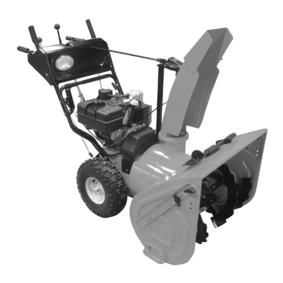
Sno-Thro
Owner/Operator Manual
Models
932105 - 8526
932506 - 8526
Transfer
Coller l'autocollant du
model &
modèle et du numéro de
serial number
série dans cet encadré.
label from
Transferir aquí la etiqueta
product
del modelo y número de
registration
serie del registro del
here.
producto.
®
ENGLISH
FRANÇAIS
ESPAÑOL
00295900 5/04
Printed in USA
Advertisement
Table of Contents

Related Manuals for Ariens Sno-Thro 932105 - 8526 , 932506 - 8526


Summary of Contents for Ariens Sno-Thro 932105 - 8526 , 932506 - 8526
- Page 1 Sno-Thro Owner/Operator Manual Models 932105 - 8526 932506 - 8526 Transfer Coller l’autocollant du model & modèle et du numéro de serial number série dans cet encadré. label from Transferir aquí la etiqueta product del modelo y número de registration serie del registro del here.
- Page 2 Facsimile PRODUCENTA – (920) 756-2407 We the undersigned, ARIENS COMPANY, certify that: Nous, soussignés ARIENS COMPANY, certifions que : Der Unterzeichnete, ARIENS COMPANY, bescheinigt, dass: La sottoscritta società ARIENS COMPANY certifica che: Nosotros, los abajo firmantes, ARIENS COMPANY, certificamos que: Undertegnede, ARIENS COMPANY, bekrefter at: Undertecknad, ARIENS COMPANY, intygar att: Allekirjoittanut, ARIENS COMPANY, vakuuttaa, että: My, niźej podpisani, ARIENS COMPANY,...
- Page 3 – Vibrasjonsmåling ved brukerens hender – Vibrationsmätning vid förarens händer – Tärinä kuljettajan käsissä – Pomiar wibracji (m/sec ) na rękach operatora Ariens Company Brillion, WI 54110-0157 USA Signature Signature Unterschrift Firma Firma Signatur Namnteckning Allekirjoitus Podpis ) in dB –...
-
Page 4: Table Of Contents
INTRODUCTION • Record Engine Model and Serial number here. PRODUCT REGISTRATION The Ariens dealer must register the product at the time of purchase. Registering the product will help the company process warranty claims or contact you with the latest service information. -
Page 5: Safety
4. Review recommended lubrication, maintenance and adjustments. 5. Review Limited Warranty Policy. 6. Fill out a Product Registration Card and return the card to the Ariens Company or go to www.ariens.com. SAFETY WARNING: POTENTIALLY HAZARDOUS SITUATION! If not avoided, COULD RESULT in death or serious injury. -
Page 6: Required Operator Training
REQUIRED OPERATOR TRAINING Original purchaser of this unit was instructed by the seller on safe and proper operation. If unit is to be used by someone other than original purchaser; loaned, rented or sold, ALWAYS provide this manual and any needed safety training before operation. - Page 7 ALWAYS remove key and/or wire from spark plug before assembly, maintenance or service. Unintentional engine start up can cause death or serious injury. Complete a walk around inspection of unit and work area to understand: • Work area • Your unit • All safety decals ALWAYS check overhead and side clearances carefully before operation.
- Page 8 DO NOT overload the machine capacity by attempting to clear snow at too fast a rate. DO NOT operate at too fast a rate. Slow down and turn corners slowly. Do not operate in reverse unless absolutely necessary. ALWAYS back up slowly. Always look down and behind before and while backing.
-
Page 9: Assembly
Keep all hardware properly tightened. Check shear bolts frequently. Maintain or replace safety and instruction labels, as necessary. NEVER store unit with fuel in fuel tank, inside a building where any ignition sources are present such as hot water heaters, space heaters, or clothes dryers. - Page 10 1. Handlebar 4. Speed Selector Assembly 5. Bolt 2. Wing Knobs 6. Shift Rod 3. Wing Nut Figure 4 Install Discharge Chute Figure 5. 1. Grease discharge chute ring on blower housing (if not already greased). 2. Remove mounting hardware from auger housing.
- Page 11 1. Spring Clip 2. Chute Crank Rod 3. Universal Joint Figure 6 Deflector Remote 1. Remove e-ring and flat washer from stud on discharge chute. 2. Route deflector remote cable between the chute and the chute pedestal. 3. Slide cable end through hole on bracket on left side of chute (Figure 7).
-
Page 12: Controls And Features
Run-in Attachment Belt 1. Start unit in a well-ventilated area according to Starting and Shut-Off in Operation. 2. Engage attachment clutch lever and run attachment for about 15 minutes. CONTROLS AND FEATURES OS6785 OS6740 Figure 8 OS6820 3. Stop unit, wait for all moving parts to stop, and remove spark plug wire. -
Page 13: Operation
WARNING: AVOID INJURY. Read and understand the entire Safety section before proceeding. WARNING: To avoid injury to hands and feet, always disengage clutches, shut off engine, and wait for all movement to stop before unclogging or working on snow thrower. Keep hands and feet away from auger and impeller. - Page 14 Throttle The throttle controls the engine speed. To increase or decrease the engine speed, adjust to: 1. Fast (normal or warm starts) 2. Part-Throttle 3. Slow (cold weather starts) 4. Stop (engine is off) OL2720 Electric Starter (932105) The electric starter will start a properly choked and cranked engine when the starter button is pushed.
-
Page 15: Filling Fuel Tank
Scraper Blade The scraper blade allows the back of the housing to keep better contact with the surface being cleared. It also prevents damage to the housing from normal wear. IMPORTANT: DO NOT allow Scraper Blade to wear too far or Auger/Impeller housing will become damaged. -
Page 16: Starting And Shut Off
3. Check Dual Handle Interlock Without the engine running, press down (engage) both clutch levers. Release attachment clutch lever. Attachment clutch should remain engaged until traction clutch lever is released, then both clutches must disengage. If clutches do not engage or disengage properly, adjust or repair before operation (see Service and Adjustments). -
Page 17: Maintenance
2. Engage Attachment Clutch - Right Hand Lever. 3. Engage Traction Drive Clutch - Left Hand Lever. Ariens Dealers will provide any service or adjustments which may be required to keep your unit operating at peak efficiency. Should engine service be required, contact an Ariens dealer or an authorized engine manufacturer's service center. -
Page 18: Check Tire Pressure
To ensure adequate lubricant level: 1. Remove filler plug (Figure 10). Lubricant 2. Add lubricant if required. Allow oil to drain IMPORTANT: Use only Ariens special gear lubricant L-2 (Part Number 00008000). GB - 18 must be at least up to bottom of lubricant filler hole with unit resting on a level-surface. -
Page 19: Service And Adjustments
GENERAL LUBRICATION IMPORTANT: Wipe each fitting clean before and after lubrication. IMPORTANT: DO NOT allow grease or oil to get on friction disc, friction plate or belts. NOTE: Apply Stens Mix Hi-Temp Grease or equivalent to the lubrication fittings. See Service Parts. - Page 20 1. Nut 2. Pressure Flange 3. Adjusting Nuts 4. Cable Support Bracket Figure 12 RUNNERS Runners should be adjusted (Figure 14) as OS6700 conditions require. 1. Position unit on a hard, flat, smooth level surface. 2. Adjust runners by inserting a spacer of desired thickness under center of scraper blade, loosen runner hardware, slide runners to flat surface.
-
Page 21: Scraper Blade
3. Reposition scraper blade flush with runners and tighten lock nuts. SHEAR BOLTS IMPORTANT: Use only Ariens shear bolts for replacement. Use of any other type of shear bolt may result in severe damage to unit. Occasionally a foreign object may enter the... -
Page 22: Attachment Drive Belt Replacement
5. Thread the adjustment pivot pin along the shift rod until it aligns with the mating hole on the speed selector lever. 6. Reinsert the pivot pin into the hole on the speed selector lever. 7. Check forward and reverse speeds. a. -
Page 23: Traction Drive Belt Replacement
6. Adjust clutch per Attachment Clutch/Impeller Brake Adjustment below. 7. Replace chute crank and secure with spring pin. 8. Replace belt cover and secure with screws. 1. Belt Finger 2. Attachment Drive Belt 3. Traction Drive Belt 4. Camshaft Pulley 5. -
Page 24: Traction Drive Clutch Adjustment
d.If spring does not stretch at least 3/16 in. (4.7 mm), or the belt tension is insufficient to throw snow properly, remove the attachment belt idler (see Figure 18) and replace it in the hole on the idler arm closer to the belt. Adjust cable slack until spring stretch is 3/16 –3/8 in. -
Page 25: Friction Disc Replacement
2. Turn the adjustment barrel up the cable to decrease the distance between clutch lever and handlebar. Turn the adjustment barrel down the cable to increase the distance between clutch lever and handlebar. 3. Check traction clutch lever distance and repeat adjustment steps if necessary. -
Page 26: Storage
03248300 Friction Disc To obtain a complete parts manual, find your model and serial number. Then go to www.ariens.com or call 1-920-756-4664. ACCESSORIES See your authorized Ariens dealer to add the additional accessories available to your Sno-Thro. Part No. Description... -
Page 27: Troubleshooting
PROBLEM PROBABLE CAUSE Engine will 1. Fuel tank is empty. 2. Fuel shut-off valve closed. crank/start. 3. Build up of dirt and residue around governor/carburetor. 4. Key Switch not in run position. 5. Ignition switch starter circuit not functioning. Engine stops. 1. -
Page 28: Specifications
Model Number Description Engine - Tecumseh Power Max - HP (Kw/min Fast Idle Speed-RPM (min Displacement - in. (cc) Electric Start Fuel Tank Capacity - qt. (L) Snow Clearing Width - in. (cm) Chute Rotation Angle Rotation Control at Handlebar Dual Handle Interlock Impeller Diameter - in. -
Page 29: Warranty
GB - 29... - Page 30 Ariens Company 655 West Ryan Street P.O. Box 157 Brillion, WI 54110-0157 920-756-2141 Fax 920-756-2407 www.ariens.com...