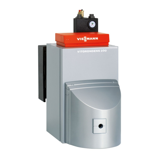
Viessmann VITORONDENS 200-T Service Instructions Manual
Type br2a, 20.2 to 53.7 kw
oil unit condensing boiler
Hide thumbs
Also See for VITORONDENS 200-T:
- Service instructions manual (32 pages) ,
- Installation instructions manual (28 pages) ,
- Technical manual (52 pages)

Related Manuals for Viessmann VITORONDENS 200-T


Summary of Contents for Viessmann VITORONDENS 200-T
- Page 1 VIESMANN Service instructions for contractors Vitorondens 200-T Type BR2A, 20.2 to 53.7 kW Oil Unit condensing boiler For applicability, see the last page VITORONDENS 200-T Please keep safe. 5600 259 UAE 6/2011...
-
Page 2: Safety Instructions
Safety instructions Safety instructions Please follow these safety instructions closely to prevent accidents and mate- rial losses. Safety instructions explained ■ the Code of Practice of relevant trade associations. Danger ■ all current safety regulations as This symbol warns against the defined by DIN, EN, DVGW, TRGI, risk of injury. - Page 3 Touch earthed objects, such as heating or water pipes, to dis- charge static loads. Repair work Please note Repairing components that fulfil a safety function can compromise the safe operation of your heating system. Replace faulty components only with original Viessmann spare parts.
-
Page 4: Table Of Contents
Index Index Commissioning, inspection, maintenance Steps - commissioning, inspection and maintenance.......... Further details regarding the individual steps............Parts lists Parts lists......................18 Overview of the assemblies................. 19 Boiler body assembly................... 20 Heat exchanger assembly (20.2 to 35.4 kW)............21 Heat exchanger assembly (42.8 and 53.7 kW)............ 23 Thermal insulation assembly................ -
Page 5: Commissioning, Inspection, Maintenance
Commissioning, inspection, maintenance Steps - commissioning, inspection and maintenance For further information regarding the individual steps, see the page indicated Commissioning steps Inspection steps Maintenance steps Page • 1. Filling the heating system..........• 2. Vent the boiler at the safety equipment block (accessory).............. - Page 6 Commissioning, inspection, maintenance Steps - commissioning, inspection and… (cont.) Commissioning steps Inspection steps Maintenance steps Page • • 20. Checking the mixer for ease of operation and leaks... 16 • • • 21. Checking the ventilation air connection to the burner (if installed)..............
-
Page 7: Further Details Regarding The Individual Steps
■ Soften fill water harder than 16.8 °dH (3.0 mol/m ), e.g. using a small soft- ening system for heating water (see Viessmann Vitoset pricelist) ■ An antifreeze suitable for heating systems can be added to the fill water. The antifreeze manufacturer must verify its suitability. -
Page 8: Vent The Boiler At The Safety Equipment Block (Accessory)
Commissioning, inspection, maintenance Further details regarding the individual steps (cont.) With safety equipment block (accessory) 1. Check the pre-charge pressure of the diaphragm expansion vessel. 2. Close the bypass valve on the KV/KR distributor. 3. Remove front insulation shell A. 4. -
Page 9: Draining The Heating System (If Required)
Commissioning, inspection, maintenance Further details regarding the individual steps (cont.) Draining the heating system (if required) A Drain Opening the boiler door... -
Page 10: Cleaning The Heating Surfaces
Commissioning, inspection, maintenance Further details regarding the individual steps (cont.) Balanced flue operation: Remove the ventilation air line before opening the boiler door. Cleaning the heating surfaces Please note Prevent components that come into contact with flue gas from being scratched or otherwise damaged. - Page 11 Commissioning, inspection, maintenance Further details regarding the individual steps (cont.) ■ Combustion residues may create thin, Cleaning agent manufacturer's yellow-brown surface discolouration details as well as hard deposits that may only become visible after removing the soot deposits. Use slightly acidic, chloride- free cleaning agents based on phos- phoric acid to remove surface disco- louration and hard deposits (e.g.
-
Page 12: Checking Gaskets And Thermal Insulation Components
Commissioning, inspection, maintenance Further details regarding the individual steps (cont.) Checking gaskets and thermal insulation components 1. Check gaskets and packing cords in 3. Replace any damaged parts. the boiler door for damage. 2. Check the thermal insulation compo- nents of the combustion chamber and the boiler door for damage. -
Page 13: Separating The Neutralising System Or Active Charcoal Filter (If Installed) From The Boiler And Connecting The Drain Hose
Commissioning, inspection, maintenance Further details regarding the individual steps (cont.) Separating the neutralising system or active charcoal filter (if installed) from the boiler and connecting the drain hose. 1. Separate hose A to the neutralising 2. Connect drain hose C to the con- system from siphon B. -
Page 14: Checking The Active Charcoal Filter (If Installed)
Commissioning, inspection, maintenance Further details regarding the individual steps (cont.) Checking the active charcoal filter (if installed) Observe the active charcoal filter manu- facturer's instructions. Checking the connections on the flue gas side for tightness Note 2. Check the heat exchanger fixings for Traces of condensate indicate a leak. -
Page 15: Cleaning The Condensate Drain Pipe And Siphon And Reconnecting To The Drain
Commissioning, inspection, maintenance Further details regarding the individual steps (cont.) Cleaning the condensate drain pipe and siphon and reconnect- ing to the drain Check that the hoses are routed without kinks and that the condensate can drain freely. Filling the siphon and neutralising system (accessory) with water Pull the supply hose (to the siphon) from the boiler condensate drain and fill with... -
Page 16: System Pressure
Commissioning, inspection, maintenance Further details regarding the individual steps (cont.) Checking the diaphragm expansion vessel and system pressure 1. Drain the system until the pressure gauge A indicates "0" or close the cap valve on the diaphragm expan- sion vessel and reduce the pressure in this vessel. -
Page 17: Instructing The System User
Commissioning, inspection, maintenance Further details regarding the individual steps (cont.) Instructing the system user The installer should instruct the user in the operation of the system. Operating and service instructions 1. Complete and detach the customer registration card: ■ Hand system users their section for safekeeping. -
Page 18: Parts Lists
Parts lists Parts lists Ordering parts The following information is required: Standard parts are available from your ■ Serial no. (see type plate A) local dealer. ■ Assembly (from this parts list) ■ Position number of the individual part within the assembly (from this parts list) -
Page 19: Overview Of The Assemblies
Parts lists Overview of the assemblies A Type plate C Heat exchanger assembly B Boiler body assembly D Thermal insulation assembly... -
Page 20: Boiler Body Assembly
Parts lists Boiler body assembly 0001 Brush handle 0008 Hose clip (2 pce) 0002 Hinge bracket 0009 Ventilation air hose adaptor (con- 0003 Sensor well nector) 0004 Cleaning brush 0010 Inlet adaptor 0005 Water distribution jet 0011 Thermal insulation block 0006 Packing 16 x 12 0012 Boiler door 0007 Ventilation air hose... -
Page 21: Heat Exchanger Assembly (20.2 To 35.4 Kw)
Parts lists Heat exchanger assembly (20.2 to 35.4 kW) 0001 Spring hook (3 pce) 0017 Corrugated pipe, front, heat 0002 Fixing element (2 pce) exchanger 0003 Boiler flue connection 0018 Thermal insulation mat, heat 0004 Boiler flue connection exchanger, front 0005 Viton gasket 0019 Bypass valve with O-rings 0006 Hose clip (2 pce) - Page 22 Parts lists Heat exchanger assembly (20.2 to 35.4 kW) (cont.) 0006 0012 0003 0012 0028 0029 0025 0028 0029 0024 0026 0012 0026 0023 0012 0027 0004 0015 0018 0027 0006 0014 0007 0010 0014 0013 0016 0005 0014 0005 0014 0022 0024...
-
Page 23: Heat Exchanger Assembly (42.8 And 53.7 Kw)
Parts lists Heat exchanger assembly (42.8 and 53.7 kW) 0001 Spring hook (3 pce) 0017 Corrugated pipe, front, heat 0002 Fixing element (2 pce) exchanger 0003 Boiler flue connection 0018 Thermal insulation mat, heat 0004 Boiler flue connection exchanger, front 0005 Viton gasket 0019 Bypass valve with O-rings 0006 Hose clip (2 pce) - Page 24 Parts lists Heat exchanger assembly (42.8 and 53.7 kW) (cont.) 0006 0012 0003 0012 0030 0030 0025 0012 0024 0026 0023 0012 0026 0030 0004 0018 0030 0015 0007 0014 0006 0010 0014 0013 0016 0005 0014 0005 0022 0024 0014 0009 0025...
-
Page 25: Thermal Insulation Assembly
Parts lists Thermal insulation assembly 0001 Service instructions 0011 Thermal insulation, outer jacket 0002 Installation instructions 0012 Side panel, right 0003 Spring hook (3 pce) 0013 Front panel 0004 Touch-up spray paint, Vitosilver 0014 Vitorondens 200 logo 0005 Touch-up paint stick, Vitosilver 0015 Coding card 0006 Thermal insulation mat, back 0016 Back panel... - Page 26 Parts lists Thermal insulation assembly (cont.) 0009 0015 0008 0017 0016 0007 0017 0003 0010 0014 0006 0011 0003 0013 0002 0001 0004 0005 0012...
-
Page 27: Commissioning/Service Reports
Commissioning/service reports Commissioning/service reports Commissioning Service Service date: Service Service Service date: Service Service Service date: Service Service Service date: Service Service Service date:... -
Page 28: Specification
Specification Specification Rated heating output = 50/30 °C 20.2 24.6 28.9 35.4 42.8 53.7 = 80/60 °C 18.8 22.9 27.0 33.0 40.0 50.0 CE designation CE-0035 CL 102 Power consumption ■ 100 % of rated heating output ■ 30 % of rated heating out- Available draught mbar Flue gas temperature... -
Page 29: Certificates
Certificates Declaration of conformity We, Viessmann Werke GmbH&Co KG, D-35107 Allendorf, confirm as sole respon- sible body that the product Vitorondens 200-T complies with the following standards: EN 267 EN 303 EN 15 034 EN 15 035 (for balanced flue operation) - Page 30 Certificates Manufacturer's certificate according to the 1st… (cont.) Oil Unit condensing boiler Vitorondens 200-T Allendorf, 01 February 2011 Viessmann Werke GmbH&Co KG pp. Manfred Sommer...
-
Page 31: Keyword Index
Keyword index Keyword index Balanced flue operation..10, 12, 16 Operating pressure......16 Boiler door ■ Fitting..........12 ■ Opening..........9 Parts list ■ Boiler body........20 ■ Heat exchanger (20.2 to 35.4 kW)..21 Checking the active charcoal filter..14 ■ Heat exchanger (42.8 and 53.7)..23 Cleaning the heating surfaces...10 ■... - Page 32 Applicability Serial no. (see boiler type plate): 7453014 7453015 7480205 Viessmann Werke GmbH&Co KG D-35107 Allendorf Telephone: +49 6452 70-0 Fax: +49 6452 70-2780 www.viessmann.com...