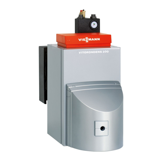
Viessmann Vitorondens 200-T Service Instructions Manual
Oil unit condensing boiler type br2a, 20.2 to 53.7 kw
Hide thumbs
Also See for Vitorondens 200-T:
- Service instructions manual (32 pages) ,
- Installation instructions manual (28 pages) ,
- Technical manual (52 pages)

Related Manuals for Viessmann Vitorondens 200-T


Summary of Contents for Viessmann Vitorondens 200-T
- Page 1 VIESMANN Service instructions for contractors Vitorondens 200-T Type BR2A, 20.2 to 53.7 kW Oil Unit condensing boiler For applicability, see the last page VITORONDENS 200-T Please keep safe. 5624 309 GB 2/2013...
- Page 2 Safety instructions Safety instructions Please follow these safety instructions closely to If you smell gas prevent accidents and material losses. Danger Safety instructions explained Escaping gas can lead to explosions which may result in serious injury. Danger ■ Do not smoke. Prevent naked flames and This symbol warns against the risk of injury.
- Page 3 Installing non-authorised components and making non-approved modifications or con- versions can compromise safety and may inva- lidate our warranty. For replacements, use only original spare parts supplied or approved by Viessmann.
-
Page 4: Table Of Contents
Index Index Product information Intended use ..................Commissioning, inspec- Steps - commissioning, inspection and maintenance ......tion, maintenance Parts lists Parts lists ....................16 Ordering parts ..................16 ■ Overview of the assemblies ..............16 Boiler body assembly ................17 Heat exchanger assembly (20.2 to 35.4 kW) ......... -
Page 5: Product Information
Product information Intended use The appliance is only intended to be installed and operated in sealed unvented heating systems that comply with EN 12828, with due attention paid to the associated installation, service and operating instruc- tions. It is only designed for the heating of water that is of potable water quality. -
Page 6: Commissioning, Inspection, Maintenance
Commissioning, inspection, maintenance Steps - commissioning, inspection and maintenance Commissioning steps Inspection steps Maintenance steps Page • 1. Filling the heating system....................• 2. Vent the boiler at the safety equipment block (accessories)......... • 3. Venting the heating system • •... -
Page 7: Filling The Heating System
Commissioning, inspection, maintenance Filling the heating system Fill water Please note Unsuitable fill water increases the level of deposits and corrosion and may lead to boiler damage. ■ Flush the heating system thoroughly before filling. Only use fill water of potable quality. ■... -
Page 8: Vent The Boiler At The Safety Equipment Block (Accessories)
Commissioning, inspection, maintenance Filling the heating system (cont.) With safety equipment block (accessories) 1. Check the pre-charge pressure of the expansion vessel. 2. Close the bypass valve on the boiler flow/return dis- tributor. 3. Remove front insulation shell 4. Open air vent valve 5. -
Page 9: Draining The Heating System (If Required)
Commissioning, inspection, maintenance Draining the heating system (if required) Fig.4 Drain Opening the boiler door Fig.5 In balanced flue operation: Remove the ventilation air line before opening the boiler door. -
Page 10: Cleaning The Heating Surfaces
Commissioning, inspection, maintenance Cleaning the heating surfaces Please note Prevent components that come into contact with hot gases from being scratched or otherwise damaged. Prevent components that come into contact with hot gases from contact with pure iron, as corrosion damage can result. Never use a wire brush or sharp objects. -
Page 11: Checking Gaskets And Thermal Insulation Sections
Commissioning, inspection, maintenance Cleaning the heating surfaces (cont.) Heating surface of the heat exchanger Fig.7 Water hose Generally, heat exchangers are cleaned with the aid of 2. Thoroughly flush the heating surface with water. a water hose from the boiler front through the hot gas flues. -
Page 12: Fitting The Boiler Door
Commissioning, inspection, maintenance Fitting the boiler door Fig.8 In balanced flue operation: Refit the ventilation air line after closing the boiler door. Separating the neutralising system or active charcoal filter (if installed) from the boiler and connecting the drain hose Fig.9 1. -
Page 13: Checking The Neutralising System (If Installed)
Commissioning, inspection, maintenance Checking the neutralising system (if installed) 1. Check the pH value of the condensate downstream 2. Reinstall neutralising system in reverse order. of the neutralising system with a pH test strip. Replace the granulate if the pH value is < 6.5. Note Part no. -
Page 14: Filling The Siphon And Neutralising System (Accessories) With Water
Commissioning, inspection, maintenance Filling the siphon and neutralising system (accessories) with water Fig.11 Pull the supply hose (to the siphon) from the boiler condensate drain and fill with a little water. Checking connections on the heating water and DHW sides and the sensor well for leaks Checking the function of the safety equipment Checking the expansion vessel and system pressure... -
Page 15: Checking The Thermal Insulation For Firm Seating
Commissioning, inspection, maintenance Checking the expansion vessel and system… (cont.) 2. If the pre-charge pressure of the expansion vessel 3. Top up with water until the charge pressure of the is lower than the static system pressure, top up with cooled system is 0.1 to 0.2 bar (10 to 20 kPa) nitrogen until the pre-charge pressure is 0.1 to higher than the pre-charge pressure of the expan-... -
Page 16: Parts Lists
Parts lists Parts lists Ordering parts The following information is required: Standard parts are available from your local supplier. ■ Serial no. (see type plate ■ Assembly (from this parts list) ■ Position number of the individual part within the assembly (from this parts list) Overview of the assemblies Fig.13... -
Page 17: Boiler Body Assembly
Parts lists Boiler body assembly 0001 Brush handle 0007 Ventilation air hose 0002 Hinge panel 0008 Hose clip (2 pce) 0003 Sensor well 0009 Ventilation air hose adaptor (connector) 0004 Cleaning brush 0010 Inlet adaptor 0005 Water distribution jet 0011 Thermal insulation block 0006 Pack 16 x 12 0012 Boiler door 0009... -
Page 18: Heat Exchanger Assembly (42.8 And 53.7 Kw)
Parts lists Heat exchanger assembly (20.2 to 35.4 kW) (cont.) 0029 Plug 0033 Connection piece with bend 0031 Silencer 0034 Flue gasket D = 80 mm 0032 Diaphragm grommet 0035 Sealing set, test ports 0033 0035 0006 0012 0003 0034 0012 0028 0029... - Page 19 Parts lists Heat exchanger assembly (42.8 and 53.7 kW) (cont.) 0010 Inlet adaptor 0021 Thermal insulation, distributor, heating water 0011 Siphon, complete flow and return 0012 Flue gasket 0022 Flue gas connection 0013 Heat exchanger 0023 Thermal insulation, heat exchanger 0014 Heat exchanger gaskets 0024 Siphon 0015 Ventilation air hose...
-
Page 20: Thermal Insulation Assembly
Parts lists Thermal insulation assembly 0001 Service instructions 0011 Thermal insulation, outer jacket 0002 Installation instructions 0012 Side panel, right 0003 Spring hooks (3 pce) 0013 Front panel with logo (0014) 0004 Touch-up spray paint, Vitosilver 0014 Vitorondens 200 logo 0005 Touch-up paint stick, Vitosilver 0015 Coding card 0006 Thermal insulation mat, back... -
Page 21: Commissioning/Service
Commissioning/service reports Commissioning/service reports Commissioning Service Service date: Service Service Service date: Service Service Service date: Service Service Service date: Service Service Service date:... -
Page 22: Specification
Specification Specification Rated heating output = 50/30 °C 20.2 24.6 28.9 35.4 42.8 53.7 = 80/60 °C 18.8 22.9 27.0 33.0 40.0 50.0 CE designation CE-0035 CL 102 Power consumption 100 % of rated heating output ■ 30 % of rated heating output ■... -
Page 23: Declaration Of Conformity
Certificates Declaration of conformity We, Viessmann Werke GmbH&Co KG, D-35107 Allendorf, confirm as sole responsible body that the product Vitorondens 200-T complies with the following standards: EN 267 EN 303 EN 15 034 EN 15 035 (for balanced flue operation) -
Page 24: Keyword Index
– Draining..............9 – Filling..............7, 8 Applicability Serial no. (see boiler type plate): 7453014 7453015 7480205 Viessmann Werke GmbH&Co KG Viessmann Limited D-35107 Allendorf Hortonwood 30, Telford Telephone: +49 6452 70-0 Shropshire, TF1 7YP, GB Fax: +49 6452 70-2780 Telephone: +44 1952 675000 www.viessmann.com...