Table of Contents
Advertisement
:'11/Jul/22
1
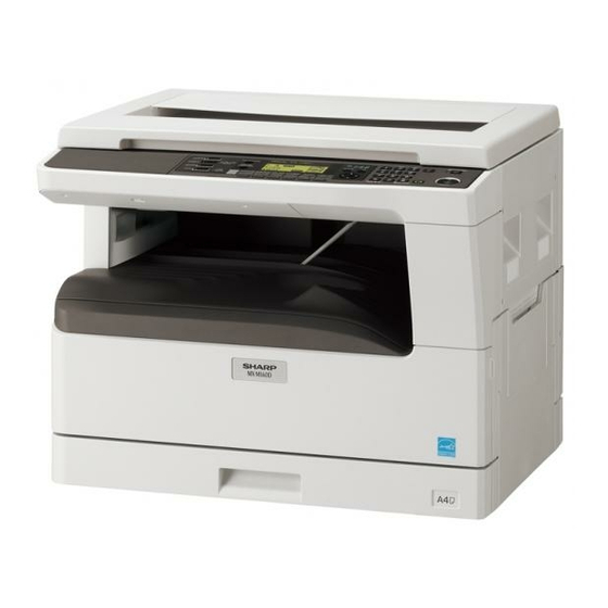
AR-5618
1
AR-5618S/5620S
AR-5618N
AR-5618D
1
AR-5620/5623
1
AR-5620N/5623N
AR-5620D/5623D
1
[ 1 ] GENERAL . . . . . . . . . . . . . . . . . . . . . . . . . . . . . . . . . . . . . . . . . 1 - 1
[ 2 ] CONFIGURATION . . . . . . . . . . . . . . . . . . . . . . . . . . . . . . . . . . . 2 - 1
[ 3 ] SPECIFICATIONS . . . . . . . . . . . . . . . . . . . . . . . . . . . . . . . . . . . 3 - 1
[ 4 ] CONSUMABLE PARTS . . . . . . . . . . . . . . . . . . . . . . . . . . . . . . . 4 - 1
[ 5 ] EXTERNAL VIEWS AND INTERNAL STRUCTURES . . . . . . . 5 - 1
[ 6 ] ADJUSTMENTS . . . . . . . . . . . . . . . . . . . . . . . . . . . . . . . . . . . . 6 - 1
[ 7 ] SIMULATIONS. . . . . . . . . . . . . . . . . . . . . . . . . . . . . . . . . . . . . . 7 - 1
[ 8 ] TROUBLE CODE LIST . . . . . . . . . . . . . . . . . . . . . . . . . . . . . . . 8 - 1
[ 9 ] MAINTENANCE . . . . . . . . . . . . . . . . . . . . . . . . . . . . . . . . . . . . 9 - 1
[10] DISASSEMBLY AND ASSEMBLY . . . . . . . . . . . . . . . . . . . . . . 10 - 1
[11] OPERATIONAL DESCRIPTIONS . . . . . . . . . . . . . . . . . . . . . . 11 - 1
[12] FLASH ROM VERSION UP PROCEDURE. . . . . . . . . . . . . . . 12 - 1
[13] ELECTRICAL SECTION . . . . . . . . . . . . . . . . . . . . . . . . . . . . . 13 - 1
Parts marked with "
Be sure to replace these parts with specified ones for maintaining the safety and performance of the set.
CONTENTS
" are important for maintaining the safety of the set.
SHARP CORPORATION
CODE : 00ZAR5618/S2E
DIGITAL MULTIFUNCTIONAL
SYSTEM
AR-5618/5620/5623
AR-5618S/5620S
AR-5618N/5620N/5623N
MODEL
AR-5618D/5620D/5623D
This document has been published to be used
for after sales service only.
The contents are subject to change without notice.
1
1
Advertisement
Table of Contents

Related Manuals for Sharp AR-5618


Summary of Contents for Sharp AR-5618
- Page 1 :'11/Jul/22 CODE : 00ZAR5618/S2E DIGITAL MULTIFUNCTIONAL SYSTEM AR-5618/5620/5623 AR-5618 AR-5618S/5620S AR-5618S/5620S AR-5618N AR-5618D AR-5618N/5620N/5623N MODEL AR-5618D/5620D/5623D AR-5620/5623 AR-5620N/5623N AR-5620D/5623D CONTENTS [ 1 ] GENERAL ......... 1 - 1 [ 2 ] CONFIGURATION .
- Page 2 Disconnect the AC cord before servicing the unit. LASER WAVE - LENGTH : 795 15mm Pulse times : 0.481ms/6mm Out put power : 5mW...
- Page 3 CAUTION FOR BATTERY DISPOSAL (For USA,CANADA) Contains lithium-ion battery. Must be disposed of properly. Remove the battery from the product and contact federal or state environmental agencies for information on recycling and disposal options.
-
Page 4: Table Of Contents
CONTENTS [1] GENERAL [9] MAINTENANCE 1. Note for servicing ......1 - 1 1. -
Page 5: General
[1] GENERAL •poorly ventilated 1. Note for servicing Pictogram The label ( ) in the fusing area of the machine indicates the following: : Caution, risk of danger : Caution, hot surface A. Warning for servicing •exposed to direct sunlight •The fusing area is hot. -
Page 6: Configuration
AR-5618S/5620S AR-5620N/5623N AR-5618N AR-5618D AR-5620D/5623D AR-D36 AR-D37 MX-NB12 (S/N model: Option installation disable) AR-5620/5623 AR-5618 AR-SP10 MX-US10 MX-US50 MX-USA0 MX-USX1 MX-USX5 Sharpdesk 1 license kit Sharpdesk 5 license kit Sharpdesk 10 license kit Sharpdesk 50 license kit Sharpdesk 100 license kit... - Page 7 :'11/Jul/22 Model AR-5618N/5620N/5623N AR-5618S/5620S AR-5618/5620/5623 Option AR-5618D/5620D/5623D AR-RP10 Reversing single pass feeder (RSPF) AR-SP10 Single pass feeder (SPF) AR-D36 250-sheet paper feed unit AR-D37 2x250-sheet paper feed unit AR-VR7 DOCUMENT COVER MX-NB12 NETWORK EXPANSION KIT (N model: X) MX-USX1 SHARPDESK 1 LICENSE KIT...
-
Page 8: Specifications
AR-5618N/5620N/5623N 2x250-sheet paper feed unit AR-D37 AR-5618D/5620D/5623D Tray 18/20cpm machine 23cpm machine AR-SP10 AR-5618/5620/5623 1st tray 7.2 sec or less 5.9 sec or less RSPF AR-RP10 AR-5618N/5620N/5623N AE mode, A4/Letter, single surface copy with OC, in polygon ready state AR-5618D/5620D/5623D D. - Page 9 15-15.9lbs Option AR-5618D/5620D/5623D only) Plain paper 60-90g/m (D→ D / D → S enable only when RSPF is installed) 16-24lbs Not available for AR-5618/5620/5623, AR-5618S/5620S Heavy paper 91-105g/m 16-24lbs (Multi paper feed enable) L. Paper exit / finishing Heavy paper...
- Page 10 :'11/Jul/22 M. Additional functions N. Other specifications AR-5618N/ Photoconductor type OPC (Organic Photo Conductor) AR-5618S/ AR-5618/5620/ 5620N/5623N Photoconductor drum dia. 30mm 5620S 5623 AR-5618D/ Copy lamp WhiteCCFL 5620D/5623D Developing system Dry 2-component magnetic brush development Charging system Saw teeth charging...
- Page 11 :'11/Jul/22 T. Printing function (1) Platform Item Content Support platform IBM PC/AT compatible machine (2) Support OS Main machine When NW expansion kit is enhanced Twain/ SPLC Custom PCL6 SPDL2 Custom PCL5e Button Manager Windows 98/Me NT 4.0 SP5 or later 2000 CD-ROM CD-ROM...
- Page 12 Gray scale: 8bit Full color: Each color RGB 8bit Scan color Black & white / binary / Gray scale / Color Interface AR-5618/5620/5623 AR-5618D/5620D/5623D: USB2.0 (High speed mode, full speed mode) AR-5618N/5620N/5623N: 10/100 base (Internal full speed connection) Scanner utility...
-
Page 13: Consumable Parts
:'11/Jul/22 [4] CONSUMABLE PARTS 1.Supply system table A. South and Central America Name Product name Content Life Remark Toner cartridge(Black) MX-235NT Toner cartridge Life setting by A4 6% document Vinyl bag Default is Toner save mode. Life is 19K. (200V series) Developer MX-235NV Developer... -
Page 14: Environmental Conditions
:'11/Jul/22 G. Asia(Except the above)/Thailand/Hong Kong Name Product name Content Life Remark Toner cartridge(Black) MX-235AT Toner cartridge Default is Toner save Life setting by A4 6% document Vinyl bag mode. Life is 19K. Toner cartridge(Black) MX-236AT Toner cartridge Default is Toner save Life setting by A4 6% document Vinyl bag mode. -
Page 15: Production Number Identification
:'11/Jul/22 3. Production number identification <Toner cartridge> <Drum cartridge> The label on the toner cartridge shows the date of production. The lot number, printed on the front side flange, is composed of 10 digits, each digit showing the following content: The lot number is of 10 digits. -
Page 16: External Views And Internal Structures
:'11/Jul/22 [5] EXTERNAL VIEWS AND INTERNAL STRUCTURES 1. Appearance Glass cleaner Document feeder cover (when the SPF/ Document glass (when the SPF/RSPF is installed) RSPF is installed) /document cover Handles Power switch Operation panel Paper output tray Front cover Paper trays Side cover Side cover handle Bypass tray guides... -
Page 17: Operation Section
AUTO PAPER SELECT indicator (Except for AR-5618S/5620S) TRAY SETTING key AUTO IMAGE key / indicator SPF/RSPF indicator (When the SPF/RSPF is installed) (AR-5618N/5620N/5623N, AR-5618/ 5620/5623 and AR-5618D/5620D/5623D) PRESET RATIO selector keys / Zoom keys Copy ratio display key indicators ZOOM indicator... -
Page 18: Motor, Solenoid, Clutch
Exhaust fan motor PSFM Cools the inside of the machine. Cooling fan motor Cools the inside of the machine. (The shape of the fan motor differs in the models of AR-5618/5620/5623 and AR- 5618D/5620D/5623D.) AR-5618S EXTERNAL VIEWS AND INTERNAL STRUCTURES 5-3... -
Page 19: Sensor, Switch
:'11/Jul/22 5. Sensor, switch Name Code Function operation Mirror home position sensor MHPS Detects the mirror (scanner unit) home position. Side door switch DSWR Side door open detection Paper exit sensor (paper exit side) POD1 Detects paper exit. Paper exit sensor (DUP side) PDPX Paper transport detection Thermistor... -
Page 20: Pwb Unit
:'11/Jul/22 6. PWB unit Name Function operation Copy lamp Inverter PWB Copy lamp control CCD sensor PWB Image scanning Main control PWB Main control PWB 2nd tray PWB 2nd tray control High voltage PWB High voltage control Power PWB AC power input/DC power control Operation main PWB Operation panel input/Display, operation panel section control USB I/F PWB... -
Page 21: Cross Sectional View
:'11/Jul/22 7. Cross sectional view Name Function/Operation Copy lamp Image radiation lamp Copy lamp unit Operates in synchronization with No. 2/3 mirror unit to radiate documents sequentially. LSU unit Converts image signals into laser beams to write on the drum. Lens unit Reads images with the lens and the CCD. -
Page 22: Adjustments
[6] ADJUSTMENTS 1.Adjustment item list Section Adjustment item Adjustment procedure/SIM No. Process Developing doctor gap adjustment Developing doctor gap adjustment section MG roller main pole position adjustment MG roller main pole position adjustment Developing bias voltage check Main charger voltage check Mechanism Image position adjustment SIM-50... - Page 23 (3)Developing bias voltage check B.Mechanism section Note: Use a digital multi-meter with an internal resistance of 10MΩ or Note: If a jam error or paper empty occurs during copying in the more. adjustment by the simulation, the image data is not saved, and therefore recopying is required.
- Page 24 9) Measure the distance H between the paper lead edge and the image <Adjustment specification> print start position. Set the image print start position set value Adjustment Spec (AUTO, 1st tray indicator ON) again. mode value value range •1 step of the set value corresponds to about 0.1mm shift. OC image lead PHOTO R/0.1...
- Page 25 c.Rear edge void adjustment (SIM50-1, SIM50-19) <Duplex mode adjustment> 1) Set a scale as shown in the figure below. 2nd print surface (auto duplex) off-center adjustment: SIM50-10 (TEXT, 1st tray indicator) A4(8.5" x 11") <Adjustment specification> Mode Set value Specifi- cation range Paper off...
- Page 26 2) Loosen the copy lamp unit wire fixing screw. 4) Loosen the set screw of the scanner drive pulley which is not in contact with No. 2/3 mirror base unit positioning plate. 5) Without moving the scanner drive pulley shaft, manually turn the scanner drive pulley until the positioning plate is brought into contact with No.
-
Page 27: Front Side
(3) Main scanning direction (FR direction) distortion 4) Loosen the mirror base drive pulley fixing screw on the front frame side or on the rear frame side. adjustment This adjustment must be performed in the following cases: •When the mirror base drive wire is replaced. When La <... - Page 28 1) Making of a test sheet Make test sheet by drawing parallel lines at 10mm from the both When La > Lb ends of A3 (11" x 17") white paper as shown below. (These lines Shift the mirror base B rail upward by the half of the must be correctly parallel to each other.) difference of La - Lb.
- Page 29 <Adjustment specification> 6) Enter the set value and press the [START] key. The set value is stored and a copy is made. Note: A judgment must be made with 200mm width, and must not be 7) Change the mode from the duplex original mode to the simplex made with 100mm width.
- Page 30 5) Change the set value with the Numeric keys to adjust the copy image density. 6) Make a copy and check that the specification below is satisfied. <Adjustment specification> Density Exposure Sharp Gray Set value mode level Chart output range...
-
Page 31: Simulations
:'11/Jul/22 [7] SIMULATIONS 3. List of simulations Main 1. Entering the simulation mode Contents code code Perform the following procedure to enter the simulation mode. Mirror scanning operation "#" key Interrupt key CLEAR key ( Interrupt key Mirror home position sensor (MHPS) status display Main code [START] key Sub code... - Page 32 :'11/Jul/22 Main Main Contents Contents code code code code Jam total counter clear Main/sub scanning magnification ratio adjustment Trouble memory clear SPF/RSPF mode sub scanning magnification ratio adjustment in copying SPF counter clear Flash ROM program writing mode (MCU) Duplex print counter clear Flash ROM program writing mode (NNB) Paper feed counter clear Image lead edge adjustment...
-
Page 33: Contents Of Simulations
:'11/Jul/22 4. Contents of simulations Main Contents Details of operation code code Mirror scanning operation When the [START] key is pressed, the home position is checked in the first place, and the mirror base performs A3 full scanning once at the set magnification ratio speed. During this scanning, the set magnification ratio is displayed. - Page 34 :'11/Jul/22 Main Contents Details of operation code code Operation panel display check <<LED check mode (ALL ON/Individual ON)>> When the [START] key is pressed in the sub code input mode, all the LED's (including the 7-seg display) are turned ON. After 5 sec of all ON, the machine goes to the sub code input standby mode. When the [AUTO/TEXT/PHOTO] key is pressed during all ON, the lighting mode is shifted to the individual ON mode, where the LED's are individually lighted from the left top, to the left bottom, to the next line top, to the bottom, and so on.
- Page 35 Main Contents Details of operation code code Warm-up display and aging with Copying is repeated to make the set copy quantity. When this simulation is executed, warm-up is started and warm-up time is counted up every second from 0 and displayed. After completion of warm-up, warm-up time count is stopped.
- Page 36 Main Contents Details of operation code code Toner motor operation When the [START] key is pressed, the toner motor is driven for 30 sec. After completion of the process, the machine goes into the main code input standby mode. When the [Interrupt] key is pressed, the machine goes into the main code input standby mode. Trouble cancel (except for U2) Trouble to write into the EEPROM such as H trouble is canceled and hardware reset is performed.
- Page 37 :'11/Jul/22 Main Contents Details of operation code code P-ROM version display The P-ROM version is displayed on the copy quantity display. The main code and the sub code are alternatively displayed by 2 digits. The display interval is same as that of the counter display. LED (AB series) LED (Inch series) Displayed version...
- Page 38 :'11/Jul/22 Main Contents Details of operation code code SPF jam total counter clear When the [START] key is pressed, the SPF jam total count value is reset to zero and displayed on the (Only when the SPF/RSPF is 7-seg display. When the [Interrupt] key is pressed, the machine goes into the sub code input standby installed) mode.
- Page 39 Main Contents Details of operation code code Auditor setting Used to set the auditor. Code number Mode Built-in auditor mode *Default Coin vendor mode Other When the coin vendor mode is selected, if the auditor setup is ON and the default tray is bypass tray, the default tray setup must be changed to the 1st tray.
- Page 40 :'11/Jul/22 Main Contents Details of operation code code Toner save mode setting Used to set ON/OFF of the toner save mode. Code number Setting Toner save OFF Toner save ON The toner save mode of the user program is also changed accordingly. The default value depends on the destination.
- Page 41 :'11/Jul/22 Main Contents Details of operation code code Side void amount setting Used to set the side void amount on the both sides. Enter a set value with the Numeric keys and press the [START] key, and the entered value will be saved and the machine will go into the sub code input standby mode.
- Page 42 Main Contents Details of operation code code Paper sensor status display The paper sensor status is displayed with the lamps on the operation panel. When each sensor detects paper, the corresponding lamp turns on. Sensor name Developer replacement required indicator Paper exit sensor Misfeed indicator(Copier) Duplex sensor...
- Page 43 Main Contents Details of operation code code Fusing temperature correction When the simulation is terminated, the current set value is displayed. When the [%] key is pressed, setting the setting is changed. When the [START] key is pressed, the set content is written into the EEPROM and the machine goes into the sub code input standby mode.
- Page 44 Main Contents Details of operation code code Toner density control Enable/ Setting is made whether the toner density control is performed or not. Disable (ON/OFF) setting When this simulation is executed, the current code number is displayed on the 7-seg display. (1=ON [Enable], 0=OFF [Disable]) Enter a code number and press [START] key, and the setting is settled and saved into the EEPROM and the machine goes into the sub code input standby mode.
- Page 45 Main Contents Details of operation code code Copy density adjustment (600dpi) Used to set the copy density for each mode. (Operating procedure) When this simulation is executed, warm-up and shading are operated, and the current set value is displayed in two digits. (Default [50])Change the set value and press the [START] key, and a copy is made according to the set value.
- Page 46 Main Contents Details of operation code code Copy exposure level adjustment, Used to adjust the shift amount and the inclination value for each density level (1 ~ 5) when the individual setting (Photo) 600dpi exposure mode is the PHOTO mode •The shift amount is the same as the gamma (gradation), and is used to set the overall brightness.
- Page 47 :'11/Jul/22 Main Contents Details of operation code code SPF exposure correction Used to adjust the exposure correction amount in the SPF mode (for the OC mode). (Only when the SPF/RSPF is (Operating procedure) installed) When this simulation is executed, the current set value is displayed. Enter the adjustment value with the Numeric keys and press the [START] key.
- Page 48 :'11/Jul/22 Main Contents Details of operation code code Main scanning/sub scanning Used to adjust the magnification ratio in the main scanning direction (front/rear) and the sub direction magnification ratio scanning direction. adjustment Enter the adjustment value with the Numeric keys and press the [START] key, and the entered value is saved a copy is made.
- Page 49 :'11/Jul/22 Main Contents Details of operation code code Image lead edge adjustment Used to adjust the copy image position and the lead edge void amount on the copy paper. This adjustment is made by adjusting the image scan start position at 100% and the print start position (resist roller ON timing).
- Page 50 :'11/Jul/22 Main Contents Details of operation code code Paper off-center adjustment Used to adjust the positions of copy images on copy paper and the center offset position when scanning the document. (Operating procedure) When this simulation is executed, the current set value is displayed. Enter the adjustment value with the Numeric keys and press the [START] key, and the entered value is stored and a copy is made.
- Page 51 :'11/Jul/22 Main Contents Details of operation code code Duplex copy memory reverse Used to adjust the memory reverse position in duplex copy. When this simulation is executed, the position adjustment current correction value is displayed. (Only when the SPF/RSPF is Enter a correction value with the Numeric keys and press the [START] key, and the entered value will installed or in the duplex mode) be saved.
- Page 52 :'11/Jul/22 Main Contents Details of operation code code Resist amount adjustment Used to adjust the contact pressure of the machine resist roller and the RSPF resist roller onto the paper. (Operating procedure) When this simulation is executed, the current set value is displayed. When the [AUTO/TEXT/PHOTO] key is pressed, the following set items are changed sequentially.
- Page 53 :'11/Jul/22 Main Contents Details of operation code code Laser power correction ON/OFF Used to set whether the laser power correction is performed or not halfway. (Invalidity) When [START] key is pressed, the entered value is saved and the screen shifts to the sub code input standby mode.
-
Page 54: Trouble Code List
[8] TROUBLE CODE LIST 2.Details of trouble codes Main Details of trouble 1.Trouble code list code code Content Duplex model memory error/ Image data error Main code Content Detail 1. The memory capacity for the duplex model code machine is wrong. Insufficient memory Duplex model memory error/ Image data error capacity. - Page 55 Main Details of trouble Main Details of trouble code code code code Content Abnormal laser output Content Copy lamp lighting abnormality Detail When the laser output is stopped, HSYNC is Detail The copy lamp does not turn on. detected. Cause Copy lamp abnormality Cause Laser abnormality...
- Page 56 Main Details of trouble Main Details of trouble code code code code Content Heat roller high temperature detection (MAIN) Content 5 continuous POUT not-reached error Detail The fusing temperature exceeds 245C°. Detail When 5 continuous not-reached jams to the paper exit sensor (POUT) occur. Cause Thermistor abnormality The jam counter is backed up and it is used in...
- Page 57 :'11/Jul/22 Main Details of trouble Main Details of trouble code code code code Content Main motor lock detection Content EEPROM read/write error (Serial communication error) Detail The main motor does not rotate. After rotation of the main motor, the motor lock Detail EEPROM access process error signal is detected for 1 sec or more.
-
Page 58: Maintenance
[9] MAINTENANCE 1. Maintenance table X:Check(Clean, adjust, or replace when required.) O:Clean :Replace :Adjust :Lubricate When Unit name Part name 100K 150K 200K 250K 300K Remark calling Drum peripheral OPC drum Cleaning blade Side seal F/R MC unit (MC charging electrode) Exchange if necessary (MC grid) Exchange if necessary... -
Page 59: Maintenance Display System
2. Maintenance display system C. DV seal attachment procedure Toner Life, Remaining a. Press and hold the [Light] keys ([Light quantity and Dark] keys) for more than 5 sec, and check *1 the machine will enter the user program mode. b. -
Page 60: Disassembly And Assembly
[10] DISASSEMBLY AND ASSEMBLY B. Charger wire Installation: The spring tip must be between two reference ribs. WARNING Before performing the disassembly procedure, be sure to •The charger wire must be free from twists or bending. remove the power cord to prevent against an electric shock. •Be sure to put the charger wire in the V groove. -
Page 61: Optical Section
2. Optical section C. Inverter PWB for copy lamp Note: When disassembling or assembling the optical unit, be careful not to touch the mirror and the reflector. Content Table glass Copy lamp unit Inverter PWB for copy lamp Copy lamp Lens unit Wire A. - Page 62 E. Lens unit <4>Loosen the CCD unit fixing screws. Note: Do not remove screws which are not indicated in the figure. If the height of the base plate is changed, it cannot be adjusted in the market. Note: The CCD/lens unit is factory-adjusted before shipping. Since these adjustments cannot be performed in the market.
-
Page 63: Fusing Section
3. Fusing section F. Wire Contents Fusing unit Thermostat Thermistor Heater lamp Upper heat roller Separation pawl Lower heat roller Separation pawl A. Fusing unit removal M4 x 8 3 point M3 x 8 special screw B. Thermostat AR-5618S DISASSEMBLY AND ASSEMBLY 10-4... - Page 64 C. Thermistor Installation: Install in direction that the sponge side (A) of the thermistor comes in contact with heat roller. Check that the thermistor is in contact with the upper heat roller. Assembly: Put the fusing harness (A) on the heater lamp (B) as shown in the figure and fix them together.<R>Place the fusing harness inside the rib (C).
- Page 65 G. Lower heat roller Assembly: When assembling the fusing front paper guide (3), Floil(GU2) temporarily fix the paper guide fixing plate with the screw so Grease(JFE552) that the paper guide fixing plate (2) is in contact with the fusing lower frame bottom (A). Lower the fusing front paper guide to the bottom of the adjustment width, and tighten the screw firmly.
-
Page 66: Paper Exit Section
:'11/Jul/22 H. Separation pawl B. Cooling fan C. Paper exit unit 4. Paper exit section Content Ozone filter Cooling fan Paper exit unit Paper exit sensor / duplex sensor Transport roller Paper exit roller A. Ozone filter S model/N model Standard model/D model AR-5618S DISASSEMBLY AND ASSEMBLY 10-7... - Page 67 :'11/Jul/22 D. Paper exit sensor / duplex sensor F. Paper exit roller (A) Exit sensor Assembly: Insert the spring pin so that the waveform (A) of the spring pin faces in the longitudinal direction of the paper exit (B) Duplex sensor drive gear long hole (B).<R>Be sure to insert two ribs (C) into the groove (D).
-
Page 68: Mcu/Nic
5. MCU/NIC 6. Optical frame unit Content Content MCU disassembly Optical frame unit NIC disassembly A. Optical frame unit A. MCU disassembly Installation: Install the optical unit in the sequence shown above. Disassembly: The connector, the havrness, and the screw are removed. -
Page 69: Tray Paper Feed Section/Paper Transport Section
7. LSU 8. Tray paper feed section/Paper transport section Content LSU unit Content Middle frame unit A. LSU unit Drive unit PS clutch/Resist roller Paper feed clutch/Paper feed roller Connection gear unit A. Middle frame unit Assembly: Do not miss the door lock pawl. Note: Do not disassemble the LSU. - Page 70 B. Drive unit D. Paper feed clutch/Paper feed roller Assembly: When assembling, be sure to check that the clutch rotation stopper is securely engaged in the frame. C. PS clutch/Resist roller E. Connection gear unit Apply rice-grain sized grease (HANARL) to the front surface of the specified gear.
-
Page 71: Bypass Tray Section
9. Bypass tray section B. Bypass tray paper feed Content Bypass tray transport roller/Bypass tray paper feed roller Bypass tray paper feed Bypass tray solenoid Bypass tray transport clutch Pressure plate unit Bypass tray paper feed clutch A. Bypass tray transport roller/Bypass tray paper feed roller Note: Push the lever at the right edge of the multi frame cover to the right upper side and remove it. - Page 72 D. Bypass tray transport clutch F. Bypass tray paper feed clutch Note: Push the lever at the right edge of the multi frame cover to the right upper side and remove it. Apply grease (FG-40H) to the gray area (UKOG-0004QSZZ). Apply grease (FG-40H) (UKOG-0004QSZZ).
-
Page 73: Power Section
:'11/Jul/22 10.Power section C. Power P.W.B. Content Power unit High voltage P.W.B. Power P.W.B. Power switch A. Power unit D. Power switch B. High voltage P.W.B. AR-5618S DISASSEMBLY AND ASSEMBLY 10-14... -
Page 74: Developing Section
11.Developing section C. MG roller Contents Developing box Developing doctor MG roller A. Developing box B. Developing doctor Adjustment: MG roller main pole position adjustment Adjustment: Developing doctor gap adjustment Note:Attach it to fit with the attachment reference when replacing the DV blade. -
Page 75: Process Section
:'11/Jul/22 12.Process section 2. Prior exposure prevention [Note] Contents • Avoid servicing in a place where there is strong light. Drum unit • Do not expose the unit to light for a long time. Main charger unit • Cover the OPC drum with light-blocking material. (When using paper, Cleaning blade use about 10 sheets of paper to block light.) [Countermeasures]... -
Page 76: Others
13.Others Contents Operation P.W.B. Tray interface P.W.B. 2nd tray paper entry sensor / Paper empty sensor 2nd tray transport clutch 2nd tray transport roller 2nd tray paper feed clutch Main motor Paper entry sensor Paper empty sensor A. Operation P.W.B. B. - Page 77 C. 2nd tray paper entry sensor / Paper empty sensor E. 2nd tray transport roller Disassembly: When the second paper feed unit is detached, the screw is removed, and the main body is lifted. F. 2nd tray paper feed clutch D.
- Page 78 H. Paper entry sensor I. Paper empty sensor AR-5618S DISASSEMBLY AND ASSEMBLY 10-19...
-
Page 79: Operational Descriptions
[11] OPERATIONAL DESCRIPTIONS 1. Paper feed operation • When copy/print movement is started, a main motor is a timing of the rotary (drive system) paper pickup, and a paper feed clutch does ON, and a paper feed roller turns. • A transportation clutch does ON, and the paper is sent to the transportation department. * By a separation plate to prevent against double feed of paper. -
Page 80: Flash Rom Version Up Procedure
:'11/Jul/22 [12] FLASH ROM VERSION UP PROCEDURE * AR-5618/5620/5623, AR-5618S/5620S, AR-5618D/5620D/5623D only. 1.Preparation 3) PC side: Boot the maintenance program. Select the model icon. Write the download data (the file with the extension dwl) to the main body. Necessary files for download •... -
Page 81: Installation Procedure
7) PC side: 12) After-process: Terminate the maintenance program, and turn on the Double click "Special (MCU)" in the main tree item to develop the sub power of the main body. tree items, and double click "DWL Download" in the sub tree items. After the download (data transmission) has been completed, exit the software program. - Page 82 3) Check that the following display is shown. 6) Check that the path to the folder which includes the maintenance tool Select "Install from a list or the specific location" and press the NEXT driver (Mainte.inf) is shown, and press the NEXT button. button.
- Page 83 3) Check that the new hardware search wizard is shown. Press the 7) Specify the folder which includes the maintenance tool driver NEXT button. (Mainte.inf), and press the OPEN button. Check that the path to the folder which includes the maintenance tool driver (Mainte.inf) is properly displayed, and press the OK button.
-
Page 84: Ar-5618N/5620N/5623N Download Procedures
6) Check to confirm that [Ethernet Address] of the installed NIC PWB is displayed, and select [Ethernet Address] and press [Next >]. 10) Execute SIM49-01 on the machine side. Select [SHARP AR-DOWNLOAD], and press [Connect]. AR-5618N 11) Boot the maintenance tool to execute downloading. -
Page 85: Electrical Section
:'11/Jul/22 [13] ELECTRICAL SECTION 1.Block diagram AR-5618S ELECTRICAL SECTION 13-1... -
Page 86: Actual Wiring Diagram
:'11/Jul/22 2.Actual wiring diagram ACTUAL WIRING DIAGRAM 1/6 AR-5618S ELECTRICAL SECTION 13-2... - Page 87 :'11/Jul/22 ACTUAL WIRING DIAGRAM 2/6 AR-5618S ELECTRICAL SECTION 13-3...
- Page 88 :'11/Jul/22 ACTUAL WIRING DIAGRAM 3/6 AR-5618S ELECTRICAL SECTION 13-4...
- Page 89 :'11/Jul/22 ACTUAL WIRING DIAGRAM 4/6 AR-5618S ELECTRICAL SECTION 13-5...
- Page 90 :'11/Jul/22 ACTUAL WIRING DIAGRAM 5/6 AR-5618S ELECTRICAL SECTION 13-6...
- Page 91 :'11/Jul/22 ACTUAL WIRING DIAGRAM 6/6 AR-5618S ELECTRICAL SECTION 13-7...
- Page 92 LEAD-FREE SOLDER The PWB’s of this model employs lead-free solder. The “LF” marks indicated on the PWB’s and the Service Manual mean “Lead-Free” solder. The alphabet following the LF mark shows the kind of lead-free solder. Example: <Solder composition code of lead-free solder> Solder composition Solder composition code Solder composition...
- Page 93 Adobe, the Adobe logo, Acrobat, and the Acrobat logo are trademarks of Adobe Systems Incorporated. • PCL is a registered trademark of the Hewlett-Packard Company. • Sharpdesk is a trademark of Sharp Corporation. • All other trademarks and copyrights are the property of their respective owners. SHARP CORPORATION...