Table of Contents
Advertisement
Advertisement
Table of Contents

Summary of Contents for Escort 3136A
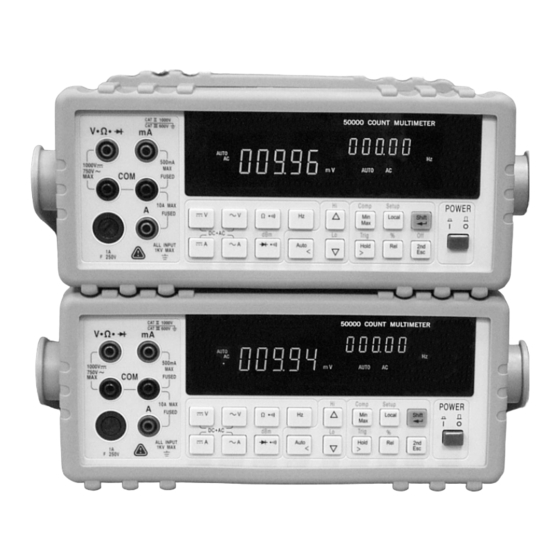
- Page 2 50000 COUNT DUAL DISPLAY MULTIMETER...
-
Page 3: Table Of Contents
Table of Contents Section 1. Introduction 1-1 Introducing the 50,000 Count Dual Display Multimeter 1-2 Features 1-3 Options and Accessories 1-4 How to use this manual 1-5 Safety Section 2. Getting Started 2-1 Introduction 2-2 Getting Started 2-3 Turning the Meter ON 2-4 Selecting Current Input Terminals and Measurement Range 2-5 Using the Pushbuttons... - Page 4 Section 5. Calibrating the Meter 5-1 Introduction 5-2 Environment Condition 5-3 Warm up 5-4 Recommended Test Equipment Section 6. RS-232 Remote Operation 6-1 Introduction 6-2 RS-232 Interface Overview 6-3 RS-232 Interface Parameter Set up 6-4 Using Commands 6-4-1 Types of Commands 6-4-2 Command Syntax 6-5 Instructions of Command Sets 6-5-1 Key Commands...
-
Page 5: Section 1. Introduction
Section 1 Introduction Introducing the 50,000 Count Dual Display Multimeter NOTE 1. This operation manual contains information and warning that must be followed to ensure user operation safety and to retain the meter safety condition. Precaution! TO ENSURE PERSONAL SAFETY AND TO AVOID DAMAGING THE METER AND THE EQUIPMENT CONNECTED, READ “GETTING STARTED”... -
Page 6: Features
Features The main features provided by the meter are: 50,000 Count Dual Display Vacuum-fluorescent Display (VFD) Low Cost and High Performances DCV, ACV, DCA, ACA, Frequency, Diode Continuity DCV Measurement to 1000V, ACV to 750V (Up 1200Vdc, 1000Vac are measurable) AC/DC Current Measurements to 10A (Up to 20A is measurable in less than 20 seconds). -
Page 7: Options And Accessories
1-3 Options and Accessories At the moment, one option is available for the meter, which option can be installed at the factory and a field installable retrofit kit option is also available: IEEE-488 interface (Optional) provides full programmability. There are two types of programming commands: IEEE 488.2 Common Commands and Standard Commands for Programmable Instruments (SCPI). -
Page 8: How To Use This Manual
1-4 How to use this manual This manual is designed to help the user to get a quick start. Though it is not necessary to read the entire manual to operate the unit effectively, we recommend the manual to be read thoroughly in order to use the meter to its full advantages. First scan the Tables of contents to be familiar with the outline of the manual. -
Page 9: Safety
1-5. SAFETY This meter has been designed and tested according to EN61010-1 (IEC1010-1), Safety Requirements for Electronic Measuring Apparatus. This manual contains information and warns which must be followed to ensure safe operation and retain the meter in safe condition. Use of this instrument in a manner not specified herein may impair the protection provided by the equipment. - Page 10 To avoid explosion, do not operate this product in an explosive atmosphere. To avoid personal injury, do not remove the cover or panel. Refer servicing to qualified personnel. Select the proper function for your measurement. To avoid electrical shock, use caution when working above 60V dc or 30V ac RMS. Disconnect the live test lead before disconnecting the common test lead.
-
Page 11: Section 2. Getting Started
Section 2 Getting Started 2-1 Introduction Section 2 describes the front panel operational keys, displays, input terminals and rear panel of the meter, adjusting handle, explains general operating features. 2-2 Getting Started Unpacking and Inspecting the Meter Carefully remove the meter from its shipping container and inspect it for possible damage or missing items. - Page 12 Rear Panel The rear panel (shown in Figure 2-2) contains a line fuse, the power-line cord connector, an RS-232 interface connector, and a cutout for IEEE-488 interface (optional) connector. Line Power Figure 2-2 illustrates the location of the Line Voltage Selector with Fuse Holder housing.
- Page 13 The “line voltage selector” is settable for 100Vac, 120Vac, 220Vac, and 240Vac line voltages. The correct fuse ratings: 250mA fuse for 100Vac or 120Vac is selected, and 125mA fuse for 220Vac or 240Vac is selected. Case, Panels and Holsters To avoid electric shock or injury, do not operate the meter without panels or case in place.
- Page 14 Grounding the Meter The meter is grounded through power cord. To avoid electric shock or injury, grounding wire in the power line cord must be connected. Operating in Explosive Atmospheres The meter does not provide explosion protection for explosive gasses or arcing components.
-
Page 15: Turning The Meter On
2-3 Turning the Meter ON To turn the meter on, press the Power button to “IN” position located on the lower right of the front panel. When the meter is turned on, the primary and secondary displays light for about 2 seconds while an internal self-test running by its digital circuitry. -
Page 16: Basic Measurement Examples
POWER 8 10 1. Power Switch 6. 2 Display Selection / Escape key 2. Measurement Function Selection 7. Local / Setup key 3. Range Selection 8. Dynamic Recording / Comparator 4. Calibration Mode Button 9. Arithmetic Function Selection 5. Shift / Enter key 10. - Page 17 Voltage, Resistance or Frequency Measurements Press the desired function button and connect the test leads as shown in Figure 2-5 to measure voltage, resistance, or frequency. The meter will select the appropriate range in the auto-range mode, and an annunciator on the display will indicate measurement units.
- Page 18 POWER Figure 2-5. Voltage, Resistance or Frequency Measurements POWER Figure 2-6. Current or Frequency Measurements VFD Brightness Control Press and hold, then press step by step to select the VFD brightness to darker level (4 steps in this function and factory setting is set at highest light level),...
- Page 19 Overload Alert The meter has provided an overload alert for voltage and current measurements. The beeper sounds tones periodically once the measuring value is exceeded the value shown as below Table 2-1: Table 2-1. Beeper Responses for overload Alert Points Measuring Function Start Alerting Value DC V...
- Page 20 Diode Continuity Tests Press to select diode continuity function, then connect the test leads across the diode under test as shown in Figure 2-7 (Reversing the polarity will reverse-bias the diode). The diode test measures the forward voltage of a semiconductor junction at approximately 0.5mA.
- Page 21 Resistance/Continuity Tests In Ohm test, press button momentarily to set continuity function ON. The sign will be lit and lock the range to 500 . Then Ω connect the test leads and across the tested circuit as shown in Figure 2-8.
-
Page 22: Rack Mounting
2-7 Rack Mounting User can mount the meter into a standard 19-inch rack using RK-01 (for single meter) Rack Mount Kit. The front and rear protective holsters can be removed when mount the meter into a rack. To install RK-01 rack mount kit, refer to following procedures and Figure 2-9 or the instructions provided with it: 1. -
Page 23: Section 3. Front Panel Operation
Section 3 Front Panel Operation 3-1 Introduction This section provides a complete description of each operation that can be performed by using the pushbuttons on the front panel. All related information for operations and functions are grouped together. 3-2 Front Panel Operations The following operations can be performed from the front panel: Select a measuring function (Vdc, Vac, Adc, Aac, resistance/continuity, frequency, and diode continuity test) for the primary display. -
Page 24: Primary And Secondary Displays
3-3 Primary and Secondary Displays The meter is 50,000 count, Vacuum-Fluorescent dual display (VFD). This display shows measuring readings, annunciator, and messages. The annunciator indicates measuring units meter’s operating configuration. The dual display allows you to see two properties (e.g. Vac and frequency) of the input signal you are measuring. - Page 25 Primary Display Secondary Display Primary Display indications: Secondary Display indications: 1. Auto range (AUTO) 9. 2 Numeric data display 2. Data/Refresh Hold mode (HOLD) 10. 2 Measurement unit 3. Dynamic recording (MIN MAX) 11. Auto range (AUTO) 4. Relative mode (REL) 12.
-
Page 26: Input Terminals
3-4 Input Terminals The input terminals, shown in Figure 3-2 are located on the left side of the front panel. The meter is protected against overloads up to the limits shown in Table 3-1. Exceeding these limits poses a hazard to both the meter and operator. -
Page 27: Initialization Of Measurement Conditions
3.5 Initialization of Measurement Conditions Power up default configuration Status: When turning the meter on, it assumes its power-up configuration. The power-up configuration set at the factory is shown in Table 3-2. As configuration data for IEEE-488 address, RS-232 baud rate, data bit, stop bit, parity, echo and so on are stored in the non-volatile memory, they are not changed when power is cycled off and on until the configurations are changed by the user. - Page 28 POWER 1. Power Switch 6. 2 Display Selection / Escape key 2. Measurement Function Selection 7. Local / Setup key 3. Range Selection 8. Dynamic Recording / Comparator 4. Calibration Mode Button 9. Arithmetic Function Selection 5. Shift / Enter key 10.
- Page 29 Table 3-3 Range Scale Value Function Range Scale Auto Ranging • 500mV, 5V, 50V, 500V, 1000V • 500mV, 5V, 50V, 500V, 750V • 500µA, 5mA, 50mA, 500mA • 5A, 10A • 500Hz, 5kHz, 50kHz, 500kHz 500, 5k, 50k, 500k, 5M, 50M Ω •...
-
Page 30: Selecting Measurement Range
3-7 Selecting Measurement Range ( Ranging operations are performed by using the buttons (see Figure 3-3). Measuring ranges can be selected automatically by the meter in “Auto-ranging” or manually operated by the user. The range setting is synchronous for dual display for current or voltage measurement. -
Page 31: Selecting Secondary Display
In manual range mode, to select higher range or lower range to the desired one. 3-8 Selecting Secondary Display To Enable the Secondary Display Mode to turn the secondary display on and select the related function with the primary display. To Disable the Secondary Display Mode cycling to turn off the secondary display ( see Table 3-4. - Page 32 Combination of Dual Display Settings Table 3-4 provides the available combination of inputs for the primary display and secondary display in the dual display mode. Table 3-4 Descriptions for Combination of Dual Display Secondary Display Primary Display Step1 Step 2 Step 3 Step 4 Step5...
-
Page 33: Entering Setup Mode
3-9 Entering Setup Mode User may select computer interface, set RS-232 interface (standard) or GPIB interface (option), and beeper mode on Setup Mode. To ensure the remote interface will operate appropriately, user may need to configure the remote interface parameters by following the procedures as shown below: (refer Table 3-5) then followed by to enter the setup mode to configure the... - Page 34 Table 3-5. Descriptions for Outline of Setup Menu Item First Second Factory Selectable Parameters Setting Tier Menu Tier Menu Remote RS-232 RS-232 or GPIB 9600, 4800, 2400, Baud Rate 9600 1200,600, and 300 Parity None None, Odd or Even Data Bit 7 or 8 RS-232 Stop Bit...
-
Page 35: Selecting Local Operation Mode
3-10 Selecting Local Operation Mode to return the operation control priority from remote mode (computer controlled) to local mode (user controlled). 3-11 Operating Arithmetic Functions Using dBm Modifier The dBm measurement is used for decibel conversion of power per 1mW consumption into a 600 Ω... - Page 36 • Operation Example: Using MIN.MAX Modifier for Dynamic Recording “MIN MAX” modifier enables the meter to store the minimum and the maximum input signals measured and elapsed time the value recorded since the “MIN MAX” modifier was selected. The definitions of “MIN” and “MAX”...
- Page 37 Operation Procedures to enable “MIN.MAX” modifier. The recording mode will rotate as the following sequences if keep pressing the key: Min.Max Min.Max for more than one second to disable “MIN MAX” modifier. then followed by to turn off all modifiers. Operation Example Selecting HOLD (Data /Refresh Hold) Modifier Data Hold...
- Page 38 Press to enter Refresh Hold mode. The present value will be held and the “HOLD ” will be lit. It will be ready to hold new measuring value once the variation of measuring value exceed the setting of variation count, and the “HOLD ”...
- Page 39 Using COMP (Compare) Function “COMP” function compares the measurement inputs with the pre-set HI and LO limits. The compare function calculation expression is based on counts without decimal point. Measurement value > High (HI) limit value Measurement value < Low (LO) limit value PASS: High limit value ≥...
- Page 40 the LO limit value. Note: 1. After set the Hi and/or the LO limits, the limits can be used for all ranges. However, at different range, the HI and the LO limits represent different values according to their respective counts. The RIGHT and LEFT button is used to select which digit will be adjusted.
- Page 41 -50000 -40000 … -10000 00000 … 50000 Press DOWN button again to -60000, then the setting value will be subtracted -50000 automatically. For digits of D4 to D1, these digits can be adjusted from –9~9 by pressing UP and down buttons. Once the value of D5 has been set to 5 or -5, any adjustment to other digits will cause the setting value to subtract 50000 or -50000 automatic, respectively.
-
Page 42: Selecting Trigger Mode
once over the maximum display of 999.99 %. This function will be used for lock range. If select this function during auto-ranging, it will lock to existing range. Press then followed by to exit percentage function Notes: 1. The Auto-ranging Relative mode or auto-ranging dynamic record will be closed when percentage function is set. - Page 43 Operation Procedures for Front Panel To enable an external trigger and trigger a measurement from the front panel, perform the following procedures: 1. Press then followed by to enter trigger mode and standby condition. The annunicator of TRIG will be lit, and display is indicated with “...
- Page 44 (This page is subject to be blank)
-
Page 45: Introduction
Section 4 Measurement Application Examples 4-1 Introduction Section 4 describes some advanced features and applications that help the user to operate the meter more effectively. The user must be familiar with the basic measurement operations described in Section 2 and Section 3 and has a basic understanding of electronics knowledge. -
Page 46: Dual Display Operation Examples
4-2-1 Dual Display Operation Examples This section will describe some practical operations of using dual display features. Measuring DC voltage and AC ripple on a rectification circuit. To display DC voltage in primary display, and AC voltage in secondary display or vise versus while testing a rectifier circuit, user may check the DC voltage supplied and its AC ripples by taking a single meter. - Page 47 Measuring AC and DC current on a rectification circuit. To display AC current in primary display and DC current in secondary display or vise versus while testing a rectifier circuit, user may check the DC current component and its AC ripples by taking a single meter. to select AC current measurement for primary display Connect the meter to the unit under test as shown below: POWER...
- Page 48 Measuring AC voltage and frequency on an AC circuit. To display AC voltage in primary display and the frequency in secondary display or vise versus while measuring an AC signal, user may check AC voltage and its frequency of an AC Power Supply or circuit by taking a single meter.
-
Page 49: Measuring Resistance
Measuring Resistance 1. Connect a resistor under test to and COM input terminals as shown below: POWER WARNING! Do not apply a voltage exceeding 500 V peak between and COM input terminals. to select Ω measurement. to select auto-ranging or manual range for primary display. -
Page 50: Measuring True Rms Ac+Dc
Measuring True RMS AC+DC The meter can measure the true rms value of ac voltages and currents. When are pressed simultaneously, the meter will measure the dc and ac signals alternatively then calculate and display the ac+dc rms value by using the following formula: dc + (AC+DC) RMS = Note: When voltage (ac+dc) measurement function is selected, the Vdc input impedance is... -
Page 51: Section 5. Calibrating The Meter
Section 5 Calibrating the Meter 5-1 Introduction CAUTION! TO AVOID DAMAGING THE DEFAULT CALIBRATION DATA STORED IN A NON-VOLATILE MEMORY, A CALIBRATION TO THE METER CAN ONLY BE DONE BY AN AUTHORIZED SERVICE CENTER AND QUALIFIED PERSONNEL WITH APPROPRIATE EQUIPMENT. THE WARRANTY WILL BE EXPIRED IF THE SEALED LABEL ON THE CAL BUTTON OF THE FRONT PANEL IS BROKEN. -
Page 52: Recommended Test Equipment
5-4 Recommended Test Equipment The test equipment requirements listed in Table 5-1 or equivalents are required to perform the calibration and performance verification test procedures. Alternative equipment may be used as long as the accuracy is at least as good as those listed. Table 5-1 Standard Equipment Requirements Standard Operating... -
Page 53: Introduction
Section 6 RS-232 Remote Operation 6-1 Introduction Section 6 describes how to operate the meter via standard RS-232 interface. It also explains the detail information of all RS-232 interface command sets used in the meter. The remote control operation enables the user either to manually operate the meter via a terminal or executes a host computer program automatically. - Page 54 Meter Null Modem Cable Figure 6-1. RS-232 connecting diagrams between the meter and a PC Setup Procedures for RS-232 Parameter User may select computer interface and set RS-232 interface on Setup Mode. To ensure the remote interface will operate appropriately, ser may need to configure the remote interface parameters.
-
Page 55: Using Commands
6-4 Using Commands Note: All RS-232 commands must be entered in the upper case. 6-4-1 Types of Commands The RS-232 commands are grouped in three types: KEY commands, SET commands, and QUERY commands. Key Commands There are 16 pushbutton keys on the front panel of the meter. User may use the Key commands <K1>... -
Page 56: Command Syntax
Query Commands The purpose of Query commands is used for requesting the meter to respond its current status. An example of a query command <R1> is used for requesting the meter to respond its primary display characters. Please refer to Section 6-5-3 for detail information about Query Commands. 6-4-2 Command Syntax Echo With echo ON, the meter echoes (returns) all the characters whatever it... -
Page 57: Instructions Of Command Sets
If RS-232 of the meter is under print-only mode, the meter will print out the measured data when the measurement cycle is completed. The format of printed data will be shown as one of the following: 1. <Measurement Data> + <CR> <LF> for only primary display mode is enabled, or 2. -
Page 58: Set Commands
6-5-2 Set Commands S1 command The S1 command is used to set up the measurement functions, ranges, and reading rates for the primary display in the meter. The S1 command is followed by two parameters <f> and <r> in order. All characters for the <f>... - Page 59 Table 6-5. Descriptions for S2 Command Command Description In S2 command, <f> parameters is used to set up the secondary display S2<f><r> measurements: <f> for specifying measuring functions with auto-ranging. <r> It is used only to select sensitivity range for AC voltage or current measurement once the primary display is frequency measurement.
- Page 60 Table 6-6 S1, S2 Commands and <f>, <r> Parameters Parameter Range <r> <f> Function Auto range 500mV 500V 1000V Auto range 500mV 500V 750V Auto range 500Ω 5kΩ Ω 50kΩ 500kΩ 5MΩ 50MΩ Auto range 500 A 50mA 500mA 2.3V Diode 2.3V Auto range...
- Page 61 Table 6-7. Descriptions for SHL Command Syntax Description SHL<m><s><nnnnn> SHL command is used to set high or low limit in counts for compare function. <m> is a necessary parameter for specifying the high or low limit. numeric number “0” is to set low limit, “1” is to set high limit. <s>...
- Page 62 Table 6-8. Descriptions for SO Command Syntax Description SO<nn> command is used to select the reference impedance for dBm SO<nn> calculation. <nn> is a two-digit decimal numeric number from “00” to “20”, representing 21 different types of reference impedance. Example: Command string “SO15” to set reference impedance at 600Ω. Impedance Impedance Impedance...
-
Page 63: Query Commands
6-5-3 Query Commands R0 command R0 command is used for requesting the meter to return its current status. The meter will then respond the following 11-digit character string to the host after receiving the R0 command: <h ><g ><v><s ><f ><r ><f ><r... - Page 64 Table 6-9. Descriptions for R0 Command and Response (cont’d) Response Description > is a two-digit hex number; each digit contains 4-bit binary codes (Bit <g <g > 7-4 and Bit 3-0) respectively to represent eight types of status about the meter.
- Page 65 Table 6-9. Descriptions for R0 Command and Response (cont’d) > is a two-digit hex number; each digit contains 4-bit binary codes (Bit <s <s > 7-4 and Bit 3-0) respectively to represent eight types of status about the meter. For earlier than “v 1.20” which can be read by RV command, the >...
- Page 66 Table 6-10 <f > and <f > Response for R0 Command ><r ><r Function Range < >= < >= < > or < >= 500mV 500V 1000V 500mV 500V 750V 500Ω 5kΩ 50kΩ Ω 500kΩ 5MΩ 50MΩ 500 A 50mA 500mA Diode 2.3V...
- Page 67 R1 command After executing R1 command, the meter will return the existing readings of primary display. For example, a returned character string “+10.234E+0” represents the primary display reading is “+10.234”. R2 command After executing R2 command, the meter will return the existing readings of secondary display.
- Page 68 Table 6-11. The syntax of returned character string Function Range Return Value ±500.00E-3 500mV ±5.0000E+0 ±50.000E+0 DC Voltage ±500.00E+0 500V ±1000.0E+0 1000V 500mV +500.00E-3 +5.0000E+0 AC / AC+DC +50.000E+0 Voltage 500V +500.00E+0 750V +0750.0E+0 ±500.00E-6 500 A ±5.0000E-3 DC / AC / ±50.000E-3 50mA AC+DC...
-
Page 69: Remote Program Examples Using Rs-232 Interface
6-6 Remote Program Examples using RS-232 interface Example Using Quick BASIC DECLARE FUNCTION TKDATA! () DECLARE SUB TKECHO () 'DEMO.BAS - This program set the meter to record Vdc measurement on the primary display - and Vac measurement on the secondary display. - The results will also be printed on the computer screen. - Page 70 FUNCTION TKDATA LINE INPUT #1, RD$ 'Read COM1. TKDATA = VAL(RD$) 'Convert a string to numeric value and return 'the value to main program. END FUNCTION SUB TKECHO LINE INPUT #1, PROMPT$ 'Get a string from COM1. Check if 'PROMPT$=<LF>+"=>" PROMPT$ = RIGHT$(PROMPT$, 2) 'Discard <LF>...
- Page 71 Example Program Using Turbo C #include <stdio.h> #include <conio.h> #define COM1 0x3f8 #define COM2 0x2f8 #define COM3 0x3e8 #define COM4 0x2e8 #define RS232 COM1 void init_rs232(void); void send(char); char read(void); void send_buffer(char*); void tkecho(char*); char* tkdata(char*); int scan_key(void); int err; void main(void) char buffer[35];...
- Page 72 void init_rs232(void) outportb(RS232+3,0x80); //Enable DLAB outportb(RS232+1,0x00); //600bps-115200bps outportb(RS232,0x0c); //9600bps outportb(RS232+3,0x03); //LCR (8N1) outportb(RS232+4,0x03); //MCR outportb(RS232+1,0x00); //IER void send_buffer(char *buffer //Send a string to RS-232 unsigned int i; for (i=0;i<=20;i++) send(buffer[i]); putchar(buffer[i]); if (buffer[i]=='\n') break; void tkecho(char *buffer) //Wait for a specific string unsigned int i=0;...
- Page 73 err=1; while(++retry<10000) if(0x20&inportb(RS232+5)) outportb(RS232,p); err=0; break; char read(void) unsigned int retry=0; err=1; while(++retry<30000) if(0x01&inportb(RS232+5)) err=0; break; return(inportb(RS232));...
-
Page 75: Section 7. Gpib Remote Operation
Section 7 GPIB Remote Operation (Option) 7-1 Introduction This section describes how to operate the meter via GPIB interface. It also explains the detail information of all IEEE 488.2 command sets and Standard Commands for Programmable Instruments (SCPI) used in the meter. -
Page 76: Commands Summary
Table 7-1 indicates the GPIB interface factory settings and user selectable communication parameters. Table 7-1. GPIB Interface Parameters Item Parameter Factory Setting Selectable Parameter Address 0 to 30 Talk ON or OFF The remote state indication of the meter will be flashing on setting to GPIB Talk ON. -
Page 77: Response Message Data Types
CONFigure is a root level keyword with the second level keyword, VOLTage, and 0.5 is the command parameter. The query command ends with a question mark “?”. Note: SCPI stems from IEEE488.1 and IEEE 488.2. Although the IEEE 488.2 standard addressed some instrument measurements, it principally dealt with common commands and syntax or data formats. - Page 78 instrument that requested service. The contents of the Status Byte Register (STB) is decided by the Service Request Enable Register (SRE), Event Status Register (ESR), Event Status Enable Register (ESE) and the output buffer. These status registers are discussed below .
- Page 79 Status Byte Register (STB) Bit7 Bit6 Bit5 Bit4 Bit3 Bit2 Bit1 Bit0 RQS/ MSS Bit 0 ~ 3: Not used. Bit 4: MAV- Message Available Data is available in the Output Buffer. Bit set to 1 when response to query placed in output buffer. Bit set to 0 when output terminator has sent to host.
- Page 80 Standard Event Status Register (ESR) Bit7 Bit6 Bit5 Bit4 Bit3 Bit2 Bit1 Bit0 Bit 0: OPC - Operation complete. This bit is generated in response to the *OPC command and indicates that the interface is ready to accept another message. Bit 1: Not used and always set to 0.
-
Page 81: Instructions Of Command Sets
Standard Event Status Enable Register (ESE) The Standard Event Status Enable Register is a mask register that allows the host to enable or disable (mask) each bit in ESR. When a bit in the ESE is 1, the corresponding bit in the ESR is enabled. When any enabled bit in the ESR changes from 0 to 1, the ESB summary bit (bit 5) of the STB register also goes to 1. - Page 82 *OPC? Description: This command pauses program execution until all operations are completed. Return ‘1’ after all pending-operations have been completed. Response: *RST Description: Place the meter to power-on-reset state, but no affect following items: The Service Request Enable or the Standard Event Status Enable. The Output Queue and interface parameter.
-
Page 83: Scpi Commands
7-5-2 SCPI Commands This subsection describes the SCPI subsystem commands for the meter. The meter is acceptable only for the upper case part of command. It is unnecessary to send complete command characters. Table 7-3. Some SCPI Symbol Conventions Text Symbol Meaning Option;... - Page 84 • CONFigure Subsystem : CONFigure [:SCALar] :VOLTage [<numeric value>] [ [ ,@1] | ,@2 ] [<numeric value>] [ [ ,@1] | ,@2 ] :ACDC [<numeric value>] [ ,@1] :DCAC [<numeric value>] [ ,@1] Description: Set the primary and secondary display to DC, AC or AC+DC voltage measurement.
- Page 85 CONFigure[:SCALar]:DIOCtest Description: Set the primary display to diode with continuity test. CONFigure[:SCALar]:FREQuency [ [ ,@1] | ,@2 ] Description: Set the primary and secondary display to frequency measurement. [ [@1] | ,@2 ] syntax is same as SCPI <channel_list> syntax. Parameter: [ [ ,@1] | ,@2 ]: Use @1 and @2 to distinguish from primary display and secondary display, respectively.
- Page 86 CONFigure[:SCALar]:OFFDual Description: Turn off the secondary display. Note: After this command, the secondary display still indicates signal source as the frequency measurement is on primary display. CONFigure[:SCALar]:OFFRecord Description: Exit the dynamic recording mode (MAX / MIN). CONFigure[:SCALar]:RANGe:AUTO <Boolean> [ ,@1] Description: Enable or disable the auto range mode.
- Page 87 Table 7-4. Return values of measuring range Return Function Range Value 500mV DC Voltage 500V 1000V 1000 500mV AC / AC+DC Voltage 500V 750V 500 A 5E-4 5E-3 DC / AC / 50mA 0.05 AC+DC 500mA Current 5000 5E+4 Resistance 500K 5E+5 5E+6...
- Page 88 •CALCulate Subsystem: CALCulate:MODE? Description: Query the calculation type. <literal> format; Returned the string of types: Response: DBM - dBm calculation. REC - record calculation LIM - comparator calculation REL - relative calculation PER – percentage calculation NOR - normal mode Example: Return “...
- Page 89 CALCulate :LIMit :UPPer [:DATA] <numeric value> :LOWer [:DATA] <numeric value> Description: Set the compare limits values (upper and lower limit value). Parameter: <numeric value> is a six-digit number; For value range: -50000 to +50000. Example: CALC:LIM:UPP 50000 ; Set the upper limit value to 50000 CALC:LIM:LOW -50000 ;...
- Page 90 • TRIGger Subsystem: TRIGger:SOURce <BUS| IMMediate > Description: Selects the source of the start trigger signal. (SCPI approved). Parameter: BUS - Selects a bus command and enter single trigger mode. IMMediate - Selects the internal trigger source and escape single trigger mode.
-
Page 91: Scpi Commands Summary
7-5-3 Command Summary of SCPI Command Parameter Std/New Explanation ABORT Event, no query Configure meter to perform specified CONFigure[:SCALar] measurement. :CURRent Set the current measurement. [<numeric value>] [[,@1]|,@2] :ACDC [<numeric value>] [,@1] :DCAC [<numeric value>] [[,@1]|,@2] Set the primary display to diode with the :DIOCtest continuity test. - Page 92 Command Parameter Std/New Explanation CALCulate Set the calculation function. :DBM Set dBm reference impedance :IMPedance <reference> [:STAT] <Boolean> :LIMit Set and query the comparator. :FAIL? :LOWer[:DATA] <number value> [:STAT] <Boolean> :UPPer[:DATA] <number value> :RECord Set the dynamic recording mode. :MAXimum :MINimum :MINMAX :OFF...
-
Page 93: Remote Program Examples Using Gpib Interface
7-6 Remote Program Examples using GPIB interface Example Using Quick BASIC GPIBEXAMPLE.BAS ' This sample program is for reference only. It can only be expected to ' function with a Digital Multimeter. ' This program reads 10 measurements from the meter and averages ' the sum. - Page 94 CALL ibclr(dvm%) IF (ibsta% AND EERR) THEN CALL gpiberr("Ibclr Error") ' Reset the meter by issuing the reset (*RST) command and delay 4 second. Instruct the ' meter to measure the volts direct current (VDC) using auto-ranging (AUTO). ' If the error bit EERR is set in IBSTA%, call GPIBERR with an error message. wrt$ = "*RST"...
- Page 95 CALL ibonl(dvm%, 0) '====================================================================== Subroutine DVMERR ‘ ‘ ' This subroutine will notify you that the meter returned an invalid ' serial poll response byte. The error message will be printed along with ' the serial poll response byte. ' The NI-488 function IBONL is called to disable the hardware and software. ' The STOP command will terminate this program.
- Page 96 IF ibsta% AND LOK THEN PRINT " LOK"; IF ibsta% AND RREM THEN PRINT " REM"; IF ibsta% AND CIC THEN PRINT " CIC"; IF ibsta% AND AATN THEN PRINT " ATN"; IF ibsta% AND TACS THEN PRINT " TACS"; IF ibsta% AND LACS THEN PRINT "...
-
Page 97: Specifications
Appendix A Specifications A-1 Introduction Appendix A describes the complete specifications of this meter. A-2 Technical Specifications Specifications assumptions: • One-year calibration cycle. • Operating temperature at 18°C to 28°C (64.4°F to 82.4°F). • Accuracy is expressed as: ± (% of reading + digits) after 30 minutes warm-up. •... - Page 98 DC Voltage Resolution, Full Scale Reading and Accuracy Full Scale Accuracy Typical Input Range Resolution Reading (1 year) Impedance 500mV 10µV 510.00 0.02% + 4 10.0MΩ 100µV 5.1000 0.02% + 4 11.1MΩ 51.000 0.02% + 4 10.1MΩ 500V 10mV 510.00 0.02% + 4 10.0MΩ...
- Page 99 AC Voltage (True RMS, AC Coupling) Resolution, Full Scale Reading and Accuracy Full Scale Accuracy (1 year) Range Resolution Reading 30 to 50 Hz 50 to 10k Hz 10k to 30k Hz 30k to 100k Hz 500mV 510.00 1% + 40 0.5% + 40 2% + 60 3% +120...
- Page 100 AC Current (True RMS, AC Coupling) Resolution, Full Scale Reading and Burden Voltage Accuracy (1 year) Resolu- Full Scale Burden Voltage Range 30 to 50 to 2k to 5k to tion Reading &Shunt Resistor 50 Hz 2k Hz 5k Hz 20k Hz 500µA 10nA...
- Page 101 AC Current (True RMS, AC+DC Coupling) Resolution, Full Scale Reading and Burden Voltage Accuracy (1 year) Full Scale Burden Voltage Range Resolution Reading &Shunt Resistor 50 to 2k Hz 2k to 5k Hz 5k to 20k Hz 10nA 510.00 0.5% + 30 1.5% + 60 500µA <0.06V/ 100Ω...
- Page 102 Diode Test/Continuity Resolution, Full Scale Reading and Accuracy Range Resolution Full Scale Reading Accuracy 2.3V 100µV 2.3000V 0.05% + 5 • Open Circuit Voltage / Test Current: +6.0V dc / 0.5mA approx. • Audible Tone: Continuous beep for continuity and single tone for normal forward-biased diode or semiconductor junction •...
- Page 103 dBm (decibel calculation) Reference Impedance 2Ω 50Ω 135Ω 800Ω 4Ω 75Ω 150Ω 900Ω 8Ω 93Ω 250Ω 1000Ω 16Ω 110Ω 300Ω 1200Ω 124Ω 500Ω 8000Ω 125Ω 600Ω Reference impedance is selectable at setup mode or during measurement. Please refer to the chapter for related operation. Default reference impedance Range and Accuracy Voltage...
-
Page 104: Specifications
A-3 General Specifications General Items Specifications Warm up time At least 30 minutes Temperature Coefficient Add 0.15 x (the applicable accuracy)/°C at 0°C to 18°C and 28°C to 50°C Operating Temperature 0°C to 50°C (32°F to 122°F) Storage Temperature -20°C to 60°C Altitude Up to 2000 M Pollution Degree... -
Page 105: Maintenance
Appendix B Maintenance B-1 Introduction Appendix B describes the basic maintenance procedures to this Multi-meter. B-2 Cleaning the Meter WARNING! To avoid electrical shock or damaging the meter, never get water inside the case. Before cleaning this meter, make sure the power is switched in OFF position and the power cord is disconnected from the AC outlet. -
Page 106: Standard Accessories
B-4 Accessories and Replacement Parts Standard Accessories: Description 30-25634-1 ~ 6 Power Cord (Refer to Table B-1 for line fuse selection) Protective holsters (Front) Protective holsters (Rear) Test Leads (Red and Black) Operation manual. 62-25038-1U Fuse, 1A/250V Fast Blow 6*31mm Optional Accessories: Description RS232 cable and PC Link software. - Page 107 P/N: 91-25195-1A Printed in Taiwan...
- Page 108 Thank you for purchasing an ESCORT instrument. For complete information and specifications on ESCORT instruments, ask our distributor for an ESCORT catalog. Digital Multi-meters Digital Clamp-ON Meters Multi-display Multi-meters Digital Thermometers Process Calibrators Digital L/C/R meters Automotive Multi-meters Sweep Function Generators...