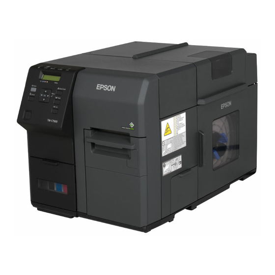
Epson TM-C7500 Series Technical Reference Manual
4-color inkjet label printer
Hide thumbs
Also See for TM-C7500 Series:
- Setup manual (33 pages) ,
- Technical reference manual (206 pages) ,
- Technical reference manual (224 pages)
Table of Contents
Advertisement
Technical Reference Guide
Series
Product Overview
Describes features for the product.
Setup
Describes setup and installation of the product and peripherals.
Handling
Describes how to handle the product.
Application Development Information
Describes how to control the printer and necessary information
when you develop applications.
Appendix
Describes general specifications and character code tables.
M00079102
Rev. C
Advertisement
Table of Contents

Related Manuals for Epson TM-C7500 Series


Summary of Contents for Epson TM-C7500 Series
- Page 1 Series Technical Reference Guide Product Overview Describes features for the product. Setup Describes setup and installation of the product and peripherals. Handling Describes how to handle the product. Application Development Information Describes how to control the printer and necessary information when you develop applications.
- Page 2 • Neither is any liability assumed for damages resulting from the use of the information contained herein. • Neither Seiko Epson Corporation nor its affiliates shall be liable to the purchaser of this product or third parties for damages, losses, costs, or expenses incurred by the purchaser or third parties as a result of: accident, misuse, or abuse of this product or unauthorized modifications, repairs, or alterations to this product, or (excluding the U.S.) failure to strictly comply with Seiko Epson Corporation’s operating and...
-
Page 3: For Safety
For Safety This document explains the functions of and how to operate this product and the software, the setup from installation until printing, information regarding maintenance, and solutions to various kinds of trouble. Be sure to read this document thoroughly before use and to use this product properly. You can easily setup this product using Install Navi. -
Page 4: Cautions On Power Supply
Do not use a damaged power cable. Doing so may cause electric shock or fire. Contact a Seiko Epson service center for advice if the power cable is damaged. Observe the following points so as not to damage the power cable: ... -
Page 5: Cautions On Handling
Shut down the product immediately if water or other liquid spills into this product. Continued use may cause electric shock or fire. Immediately unplug the product and contact your dealer or a Seiko Epson service center for advice. Never disassemble or repair this product. Tampering with this product may result in injury or fire. -
Page 6: Cautions On The Ink Cartridge
Cautions on the Ink Cartridge Do not touch the IC chip on the cartridge. Doing so may cause operating/printing malfunction. This product uses ink cartridges equipped with an IC chip that monitors the amount of CAUTION ink used by each cartridge. Cartridges are usable even if they are removed and reinstalled. -
Page 7: Caution Label
Caution Label The caution label on the product indicates the following precaution. Take care not to injure your fingers on the fixed blade of the autocutter. CAUTION Restriction of Use When this product is used for applications requiring high reliability/safety, such as transportation devices related to aviation, rail, marine, automotive, etc.;... -
Page 8: Table Of Contents
Contents ■ For Safety ..........................3 Key to Symbols ............................3 Cautions on Installation .........................3 Cautions on Power Supply........................4 Cautions on Handling ..........................5 Cautions on the Ink Cartridge ......................6 Caution Label ............................7 ■ Restriction of Use ........................7 ■ About this Manual ........................ 7 Aim of the Manual ..........................7 Manual Content .............................7 ■... - Page 9 Setup..................... 31 ■ Install Navi........................... 32 ■ Work flow to set up this product without using the Install Navi ........34 ■ Checking the Items Included in the Package ..............35 ■ Installing the Printer......................36 Location Appropriate for Installation ....................36 ■...
- Page 10 Barcode and 2D Symbol Font Printing on .NET Environment............126 Banding Reduction ..........................128 Start the PrinterSetting from the printer driver.................129 Setting EPSON Status Monitor 3......................130 Restricted items of printer drivers......................136 ■ USB Printer Class Device Replacement Service............137 Uninstallation of USB Printer Class Device Replacement Service ..........137 Restrictions in USB Printer Class Device Replacement Service .............138...
- Page 11 Application Development Information........159 ■ How to Control the Printer....................159 Using label printing application ....................... 159 Using the Epson Inkjet Label Print SDK ..................... 160 Using the ESC/Label commands...................... 160 Changing Printer Settings and Replacing the Printer..............161 ■ Software and Manuals ..................... 166 ■...
- Page 12 Appendix..................171 ■ Product Specifications ..................... 171 Operating Environment ........................172 Printing Specifications ........................173 Paper Specifications ..........................174 Paper detection method ........................182 Print Area and Cutting Position ......................183 Electrical Characteristics ........................193 Reliability..............................194 Environmental Conditions........................195 External Dimensions..........................196 ■ Consumable Product Specifications................199 Ink Cartridge ............................199 Maintenance Box ..........................199 ■...
-
Page 13: Product Overview
Chapter 1 Product Overview Product Overview This chapter describes features of the product. Features TM-C7500 is a 4-color inkjet label printer that offers high processing speed, operability and reliability required for on-demand label printing. Printing High speed printing • Actualizes 300 m/sec high speed printing. (600 dpi x 1200 dpi line inkjet printing) •... -
Page 14: Operability
• The printer driver has a built-in barcode font and can print high quality barcodes with superior readability. Can be used from a .NET environment application. • EPSON Inkjet Label Printer SDK (a Windows printer driver is used) that supports the customer's printing application development is available. -
Page 15: Other Features
Chapter 1 Product Overview Other Features • USB interface and Ethernet interface are standard. Can be used as a local printer of a computer or network printer. • The auto-cutter is equipped by default. Paper can be cut by a command from applications or panel switch operations. -
Page 16: Part Names And Functions
Part Names and Functions Front Side Paper Set Cover Control Panel Roll Paper Cover Maintenance Box Cover Ink Cartridge Cover Rewinder Connection Cover Front Cover Name Description Operation Panel Perform various settings of this product. For detail, see "Operation Panel" on page 17 Ink Cartridge Cover Open this cover to install/replace the ink cartridge. -
Page 17: Operation Panel
Chapter 1 Product Overview Operation Panel Paper LED (Power) LED Status Pause Paper Ink LED Status LED Pause LED Back Feed Pause Pause Button Back Feed Button Menu Feed Cancel Cancel Button Feed Button Cut Button (Power) Button Selection/Setting Button Name Description (Power) LED... - Page 18 Name Description (Power) Button Turns on/off the printer. When the Dip switch 1 is ON, this product can be reset. "Setting the Dip Switches" on page 140 Selection/Setting Button Use this button to select/set the menus and items displayed on the LCD. (Menu) Button: Displays the menu screen.
-
Page 19: Rear Side
Chapter 1 Product Overview Rear Side Dip Switch Cover USB Connector Ethernet Connector Dip Switch Wire Saddle Dip Switch Cover mounting screw AC Inlet Air Vent Name Description USB Connector For connecting a USB cable. Ethernet Connector For connecting a LAN cable. Wire Saddle Pass the USB cable through this saddle to prevent disconnection of the USB cable. -
Page 20: Nozzle Verification Technology
Nozzle Verification Technology This product has an "Nozzle Verification Technology” that detects missing dots. You can select the “Nozzle Verification Technology Enable / Disable”, “Nozzle check interval” and/or “Threshold of clogged nozzles”, depending on level of requirement for missing dots. And when unrecoverable clogging occurs, this printer is able to carry out supplemental printing using a nearby nozzle. - Page 21 Chapter 1 Product Overview Setting the Nozzle Verification Technology Enable / Disable Enable / Disable of Nozzle Verification Technology is set. The factory setting is “Enable”. Settings It can be set from the setting menu of the product and PrinterSetting. "Setting panel switch"...
-
Page 22: Dot Substitution
Dot substitution The dot substitution is a function to perform supplemental printing using nearby nozzles, when nozzle clogging detected by the Nozzle Verification Technology was not cleared even after several auto print head maintenance. The maximum number of clogged nozzles that can be automatically supplemented is 16. However, supplementation cannot be performed adequately in the case of clogging of an adjacent nozzle. -
Page 23: Periodic Auto Cleaning
Chapter 1 Product Overview Periodic auto cleaning A periodic auto cleaning can be executed to maintain the printer heads in good condition. A periodic auto cleaning takes 2 to 30 minutes. No printing can be performed during the cleaning. You can set the time for implementation of periodic auto cleaning. If periodic auto cleaning implementation time setting is disabled, periodic auto cleaning will be implemented at a time that the printer judges necessary, for example when a fixed time has elapsed since the previous periodic auto cleaning. -
Page 24: Status/Error Indications
■■■■■■■■■■■■■■■■ ▼ ● ✓ ✓ ✓ the power is turned ■■■■■■■■■■■■■■■■ For 2 to 4 seconds The model name is displayed on EPSON ▼ ● ✓ ✓ ✓ after the power is LCD. TM-C**** turned ON 4 seconds after the... - Page 25 Chapter 1 Product Overview Printer Status Description Idling (with power If the product does not operate for POWER SAVING saving) 30 minutes or more while the power ● ● * * * * is ON, it moves to the power saving mode.
- Page 26 Printer Status Description ROLL COVER OPEN Roll paper cover The Roll paper cover is open. ● ▼ ● open error (*) * * * * FRONT COVER OPEN Front cover open error The Front cover is open. ● ▼ ● * * * * PAPER COVER OPEN Paper cover open...
- Page 27 Non-genuine ink cartridge is used. cartridge (*) CARTRIDGE MAY NOT PERFORM AT OPTIMUM LEVEL CONTINUE? ● ● CONTINUE? PLEASE USE GENUINE EPSON INK CARTRIDGE * * * * NO M/B Maintenance box not The maintenance box is not ● ● ● ▼...
- Page 28 Printer Status Description MAINTENANCE BOX Maintenance box The maintenance box error ● ● ● ERROR CSIC error (*) occurred. ▼ * * * * MAINTENANCE BOX Maintenance box The maintenance box is near full. ● ▼ NEAR FULL near full (*) * * * * REPLACE Maintenance box full...
-
Page 29: Ink Cartridge And Maintenance Box Status
Chapter 1 Product Overview Ink Cartridge and Maintenance Box Status You can check the status of the printer, the ink cartridges of each color, and the maintenance box from the LCD. Row 1: displays the printer’s status Row 2: displays the status of the ink cartridges and maintenance box Amount used for the maintenance box Amount remaining for the ink cartridge... -
Page 30: Beeper
Beeper When an error occurs, the beep sounds. The beeper continues to beep until all the causes of error are removed. When “Completion Beeper Setting” is enabled, the printer performs “Beeper sound when the printer is not in an error state” shown in the below table. •... -
Page 31: Setup
Chapter 2 Setup Setup This chapter describes the installation and setup of the product and peripherals necessary before using this product. This product can be set up using the following methods. • Perform setup following the Install Navi on the included CD-ROM. (page 32)... -
Page 32: Install Navi
Install Navi By using the Install Navi, this product can be set following the steps shown on the screen. Unpacking and Installing the this product in advance. See the following for details. • Checking the Items Included in the Package (page 35) •... - Page 33 Chapter 2 Setup See the following if you are installing the rewinder. • How to install the REWINDER (page 45) • Attaching the paper leading edge to the rewinder (page 47) This completes the setup of the product.
-
Page 34: Work Flow To Set Up This Product Without Using The Install Navi
Work flow to set up this product without using the Install Navi This chapter explains the installation and settings for this product and the peripherals necessary before using this product. Checking the Items Included in the Package (page 35) Installing the Printer (page 36) Connecting the Power Cable (page 37) Connecting the Interface Cable (page 37) -
Page 35: Checking The Items Included In The Package
Checking the Items Included in the Package When using the printer for the first time, check the items included in the package. The items included in the package are as follows: TM-C7500 Series Ink cartridge(C, M, Y, K)* CD-ROM USB cable... -
Page 36: Installing The Printer
Installing the Printer Secure sufficient space in a location appropriate for installation. Two people are required to lift up this product. CAUTION The weight of this product is approximately 37 kg {81.57 lb}. When lifting up this product, place the product between two people as shown in the figure below and hold the recessed areas on both sides of the product. -
Page 37: Connecting The Power Cable
Chapter 2 Setup Connecting the Power Cable Connect the power cable by following the steps below. Use only AC 100 V for the power supply. Using other type of power supply may cause electric shock or fire. Be sure to install this product in the vicinity of a power outlet so that you can immediately WARNING unplug the product if some fault or other problem occurs. -
Page 38: Turning On/Off
Turning On/Off This section describes how to turn on/off the product. Turning On Press (Power) button. (Power) LED lights up and the power turns on. Turning Off Hold down (Power) button for one second or more. (Power) LED turns off and the power turns off. -
Page 39: Installing The Ink Cartridge
Chapter 2 Setup Installing the Ink Cartridge Install the ink cartridge by following the steps below. Read the handling instructions carefully before installing the ink cartridge. "Replacing the ink cartridge" on page 41 "Ink Cartridge" on page 199 CAUTION Turn on the product. Open the ink cartridge cover. - Page 40 Close the ink cartridge cover. Ink charging starts. The (Power) LED flashes during ink charging. Never open any cover on the product or turn off the product during ink charging (while the (Power) LED is flashing). Doing so during ink charging will consume a large amount of ink, which may require replacement of the ink cartridge before completion of charging.
-
Page 41: Replacing The Ink Cartridge
Chapter 2 Setup Replacing the ink cartridge As the product is being used, the status of the ink cartridge changes as shown below. • INK LOW • REPLACE INK INK LOW When the ink level in the ink cartridge becomes low, the Ink LED flashes and [INK LOW] is displayed on LCD. -
Page 42: Installing The Maintenance Box
Installing the Maintenance box The Maintenance box is already installed when the product is shipped. Do not dismantle the Maintenance box. Do not touch the IC chip on the cartridge. Keep out of reach of children, and do not drink. CAUTION ... - Page 43 Chapter 2 Setup REPLACE MB When there is almost no space that can be used in the Maintenance box, the Ink LED is lit, [REPLACE MB] is displayed on LCD and the product changes to offline. Change to a Maintenance box with enough space using the following steps. Check that the INK LED on the printer is lit up, and check that the maintenance box displays "REPLACE MAINT B"...
- Page 44 Put the maintenance box into the plastic bag for disposal of used maintenance box. Push the new maintenance box gently in, with its labeled surface upward. Close the maintenance box cover. When the maintenance box replacement is completed, the INK LED turns off, and printing can be performed.
-
Page 45: Rewinder
Chapter 2 Setup REWINDER How to install the REWINDER Install the rewinder with the following steps. Open the rewinder connection cover on the front of the printer. Insert the rewinder's power transmission gear into the cover opening. Make sure that the mark at the bottom of the rewinder is aligned with the plate edge. -
Page 46: Removing The Rewinder
Removing the rewinder Pull the rewinder's lever in the direction of the arrow below, and remove the rewinder from the printer. -
Page 47: Attaching The Paper Leading Edge To The Rewinder
Chapter 2 Setup Attaching the paper leading edge to the rewinder Attach the paper to the rewinder with the following steps. Remove the rewinder's flange. Press the Feed button and bring out approx. 800 mm {31.50"} of paper from this product. Pass the paper under the roller and onto the rewinder, as in the figure below. - Page 48 Fix the tip of the paper to the core or insert it into the gap of the rotation axis. If a roll core is used: Fasten the paper leading edge to the core with tape, then turn the rewinder flange (roughly 2 rotations) to take up the slack paper.
-
Page 49: Setting The Paper
Chapter 2 Setup Setting the Paper Setting the Roll Paper Set the roll paper by following the steps below. Turn on the product. Open the paper set cover. Open the roll paper cover. - Page 50 Pull out the roll paper flange while holding the release lever of the roll paper flange between your fingers. Release Lever Roll Paper Flange Attach the roll paper to the spindle, and push the core of the roll paper as far as possible so that it is securely fit it into place.
- Page 51 Chapter 2 Setup Attach the roll paper flange to the spindle while holding the release lever of the roll paper flange between your fingers. Push the flange to the bottom to align it with the roll paper width. Release Lever Roll Paper Flange Open the paper hold inside the paper set cover.
- Page 52 Insert the paper along the paper guide (a). Align the end of the paper with mark. Mark Paper Guide (a) Move the paper guide (b) to align it with the paper width while pushing the paper guide (b) lever. Paper jams or misprints may occur if the position of the paper guide (b) is not aligned with the paper width....
- Page 53 Chapter 2 Setup Insert the end of the paper into the paper feed slot. When you insert approx. 4 cm, the paper is automatically fed. The Paper LED turns off when the paper is set properly. If the Paper LED stays on, the paper is not set properly.
- Page 54 If the paper is loose, turn the roll paper flange in the direction of the arrow to tighten the paper. Close the roll paper cover. Close the paper set cover. Press the Pause button.
-
Page 55: Setting The Fanfold Paper
Chapter 2 Setup Setting the Fanfold Paper Set the fanfold paper by following the steps below. Turn on the product. Open the paper set cover. Set the fanfold paper referring to Step 8 to 12 in " Setting the Roll Paper". -
Page 56: How To Eject Paper For Paper Replacement
How to eject paper for paper replacement Discharge the paper with the following steps. Turn on the product. Cut the paper, using the Cut button. Press the Back Feed button for 1 second or longer. Open the paper set cover. Open the paper guide's two paper hold levers, and remove the paper. -
Page 57: Ejection Angle Of Printed Paper
Chapter 2 Setup Ejection Angle of Printed Paper Make sure paper is ejected straight from the paper ejection guides, as shown in the illustration. If paper is not ejected straight due to such causes as an obstruction, the print result may be distorted. ... -
Page 58: Printer Settings
Printer settings Various settings of the product can be done from the menu screen. This section explains basic setting procedures. Language Setting Set the language used for the messages displayed on the LCD by following the steps below. Turn on the product. Press the (Menu) button to display the menu. -
Page 59: Time Setting
Chapter 2 Setup Time Setting Set the current date and time by following the steps below. Turn on the product. Press the (Menu) button to display the menu. Select [PRINTER SETUP3] and press the OK button. Select [CLOCK] and press the OK button. Enter the current date and time.... - Page 60 Select [NETWORK SETUP] and press the OK button. Select [IP ADDRESS] and press the OK button. Select [AUTO] or [MANUAL]. When [AUTO] is selected, the network settings are complete. When [MANUAL] is selected, go to Step 7 and set IP address, etc. Select [IP ADDRESS] and press the OK button.
-
Page 61: Paper Settings
Chapter 2 Setup Paper settings The media source, media type, media form and media detection are set. • When using a Windows driver: "Set using a printer driver" on page 61 • When not using a Windows driver: "Setting using the PrinterSetting" on page 64 •... - Page 62 The "Media Detection Settings" screen is displayed. Select the media source and media detection, and click [OK]. Click [User Defined]. The "User Defined Media Layout" screen is displayed. Enter Media Layout Name. If there is an existing defined media layout, you can create a new layout based on the defined media layout.
- Page 63 Chapter 2 Setup Enter the size of the paper (unit: mm). When enlarging the print area, put a checkmark in [Borderless Printing] to eliminate margins. When the margins are zero, the print may extend outside of the media/label. Use it accordingly. ...
-
Page 64: Setting Using The Printersetting
Setting using the PrinterSetting Turn on the product. Start PrinterSetting. "Starting the PrinterSetting" on page 79 The "Media settings" screen is displayed. Set the media source/media detection/media type. Click [Apply settings]. - Page 65 Chapter 2 Setup From the items on the left, select [Layout settings]. Click [Edit layout...]. The "User Defined Media Layout" screen is displayed. Enter Media Layout Name. If there is an existing defined media layout, you can create a new layout based on the defined media layout.
- Page 66 Enter the size of the paper (unit: mm). When enlarging the print area, put a checkmark in [Borderless Printing] to eliminate margins. When the margins are zero, the print may extend outside of the media/label. Use it accordingly. When [Borderless Printing] is checked, [Feather Edges] can be checked. When [Feather Edges] is checked, gradation processing is performed on the margin areas.
-
Page 67: Setting With The Panel Switch
Chapter 2 Setup Setting with the panel switch Turn on the product. Press the (Menu) button to display the menu. Select [PRINTER SETUP1] and press the OK button. Select [MEDIA SOURCE] and press the OK button. Select media source and click the OK button. Select one from INTERNAL ROLL/EXTERNAL FEED. -
Page 68: Test Printing
Test printing You can check whether the printer is operating normally by printing the nozzle check pattern. Perform nozzle check printing by following the steps below. You can use nozzle check to check whether the nozzle is clogged from the printed pattern. Turn on the product. -
Page 69: Test Printing
For Windows Server 2003 R2: Click [Printers and Faxes] on [Start] menu. Right-click [EPSON TM-C7500], and click [Printing References]. Registered name of this product to display in the case of the [EPSON TM-C7500]. The Properties screen is displayed. Click [Print Test Page]. -
Page 70: How To Display The Printer Driver
For Windows Server 2003 R2: Click [Printers and Faxes] on [Start] menu. Right-click [EPSON TM-C7500], and click [Printing References]. The printer driver screen is displayed. Registered name of this product to display in the case of the [EPSON TM-C7500]. -
Page 71: Handling
Chapter 3 Handling Handling This chapter describes basic handling of the printer. List of printer setting items Setting item Panel Button PrinterSetting Printer Driver ✔ ✔ ✔ Cleaning ✔ ✔ ✔ Nozzle check ✔ ✔ ✔ Media type ✔ ✔ ✔... - Page 72 Setting item Panel Button PrinterSetting Printer Driver ✔ ✔ ✔* Operation when paper replaced ✔ Operation cancellation via panel ✔ ✔ ✔* Specified-time cleaning ✔ ✔ ✔* Time for specified-time TCL ✔ ✔ ✔* LCD brightness ✔ ✔ ✔* LCD contrast ✔...
- Page 73 Chapter 3 Handling Setting item Panel Button PrinterSetting Printer Driver ✔ Subnet mask ✔ Default gateway ✔ ✔* Selection of character code tables ✔ ✔* Registration of fonts, images and templates ✔ Setting preset images Enable/Disable of Panel button (Cancel, ✔...
-
Page 74: Setting Panel Switch
Setting panel switch Settings menu item Available settings Default setting YES CLEANING NO YES NOZZLE CHECK NO PLAIN PRINTER SETUP1 MEDIA TYPE MATTE2 MATTE1 MATTE2 SYNTHETIC GLOSSY DIE-CUT LABEL MEDIA FORM DIE-CUT LABEL ... - Page 75 Chapter 3 Handling Settings menu item Available settings Default setting CUT POSITION -35 to +35 [pixel] PRINTER SETUP1 PAPER FEED ADJUSTMENT -99 to +99 YES PRINT PAPER FEED ADJ. PATTERN NO ENABLE NOZZLE VERIFICATION TECHNOLOGY ENABLE PRINTER SETUP2 ...
- Page 76 Settings menu item Available settings Default setting OFF PRINTER SETUP3 LCD BRIGHTNESS LEVEL2 LEVEL1 LEVEL2 LEVEL3 0 to 10 LCD CONTRAST OFF BEEPER VOLUME MEDIUM LOW MEDIUM HIGH MAX DISPLAY INK LOW LED DISPLAY ...
- Page 77 Chapter 3 Handling Settings menu item Available settings Default setting EPSON PREFERRED COLOR CONTROLS MODE EPSON EPSON STANDARD PREFERRED INK PROFILE -6 to +4 RATIO OF BLACK -6 to +4 (Available settings vary with paper type) ENABLE...
-
Page 78: Printersetting
PrinterSetting Administrator's privilege is required to execute PrinterSetting. The PrinterSetting is a utility to setup this product. The following can be set with the PrinterSetting. Item Description Page Media settings* Sets media used in this product. page 82 Sets the media layout. Performs a User defined Layout settings* media layout in which media form or printing page 83... -
Page 79: Starting The Printersetting
Starting the PrinterSetting Start the PrinterSetting with the following methods. Turn on the product. Select [Start] - [All Programs] - [Epson] - [TM-C7500 Series] - [PrinterSetting]. The [Select printer] screen is displayed. Select a search target and click [Search]. This product is displayed in the list. Select a printer to set and click [OK]. - Page 80 Start the PrinterSetting.
-
Page 81: Apply Settings
Chapter 3 Handling Apply settings After setting each item, click [Apply settings] to change the settings of this product. -
Page 82: Media Settings
Media settings Sets the media to be used in this product. This setting screen is not displayed if you started PrinterSetting from the printer driver. Item Description Media detection Media source Sets the media source. settings Media detection Sets the media detection method. Print settings Media coating type Sets the media type. -
Page 83: Layout Settings
Chapter 3 Handling Layout settings Sets the media layout or creates a new User defined media layout. This setting screen is not displayed if you started PrinterSetting from the printer driver. Item Description Layout settings Media layout Sets the media layout. Edit layout Creates a new user defined media layout. - Page 84 Layout settings Item Description Media layout name Sets the media layout name. Enter a name. Defined media layout The defined media layout in the list is displayed. Media form Sets the media form. Layout Information (mm) Sets the media width, label width, left gap, label length and blackmark interval.
-
Page 85: Position Adjustment
Chapter 3 Handling Position adjustment Adjusts the print start position or cut position. Item Description Justify Print start position Adjusts the print start position in the vertical direction. adjustment Click [Start adjustment...] to adjust the position. (Vertical direction) Print start position Adjusts the print start position in the horizontal direction. - Page 86 Apply settings Click [Start adjustment...] and the following screen is displayed. (Explained using the print start position adjustment (vertical direction) as an example.) Enter the adjustment value and click [Apply settings]. The confirmation screen is displayed. Click [Yes] to execute the adjustment. The results are displayed.
-
Page 87: Print Results Adjustment
Chapter 3 Handling Print results adjustment Adjusts the color preset or the barcode. This setting screen is not displayed if you started PrinterSetting from the printer driver. Item Description Color preset Mode Sets the mode. Ink profile Sets the ink concentration. Depending on the media in use, adjust accordingly to secure the print quality. -
Page 88: Store Data In The Printer
Store data in the printer Registers images, templates, fonts, and character code tables to the printer. Item Description Image (Only .png) Registers an image used for preprinting or templates. Template Registers a template. Font (Only .ttf and .tte) Registers a font to apply to print data. Character code table Changes the character code used for printing. -
Page 89: Background Image Settings
Chapter 3 Handling Background image settings Sets a preset image. Register a preset image if you are using the Windows driver from Zebra Technologies Corpora- tion, or an application that directly controls the ZPLII or ESC/Label command. For details about the preset images, see "Preset image"... - Page 90 Printing the preset image Use this function when using the Windows driver from Zebra Technologies Corporation, or when using an application that directly controls ZPLII or ESC/Label commands. The preset image printing is not possible with an Epson printer driver.
-
Page 91: Print Head Maintenance
Chapter 3 Handling Print head maintenance Performs a print head maintenance or nozzle check and sets periodic cleaning. Item Description Print head Manual head Perform the nozzle check to automatically recover from the nozzle maintenance cleaning dot dropouts. Click [Start] to start a nozzle check. Nozzle check Prints nozzle check patterns and checks clogged nozzles. -
Page 92: Printer Settings
Printer settings Sets the printer. Item Description Preferences Power on action Sets the action when the power is turned on. Paper Sets the action when the paper is replaced. replacement action Operations after Sets if the media should be cut after printing. printing Notification Beeper volume... -
Page 93: Panel Settings
Chapter 3 Handling Panel settings Display settings for the panel buttons and LCD are set. Item Description Panel button Cancel button Enables/disables the Cancel button. settings Feed button Enables/disables the Feed button. Cut button Enables/disables the Cut button. LCD settings LCD brightness Sets the LCD brightness. -
Page 94: Nozzle Check Settings
Nozzle check settings Sets the nozzle check. Item Description Nozzle check Nozzle Verification Enables/disables the auto nozzle check. settings Technology Threshold of Sets the threshold of clogged nozzles. clogged nozzles The standard setting is '0'. Additional auto Sets the additional auto nozzle check during printing. nozzle check during printing Nozzle check... -
Page 95: Advanced Settings
Chapter 3 Handling Advanced settings Sets the advanced settings on the printer. Item Description Paper feed adjustment (Mech wear) Sets the paper feed adjustment (Mech wear) when images fade. Adjust media detection sensor Starts the calibration of the detection sensor. Set prefix text* Sets the prefix text. - Page 96 Executing replacement settings Click [Set] for [Replacement Settings] to display the "Replacement Settings" window. Select the [Printer in use (Monochrome/Color)] and [Resolution of the printer in use], then click [Apply settings]. The confirmation window is displayed. Click [Yes] to reflect the settings. The result is displayed.
-
Page 97: Initialize Printer
Chapter 3 Handling Initialize printer Initializes the printer. Item Description Initialize Factory reset Initializes the printer to the factory settings. Erase memory Initializes the extended memory. -
Page 98: Printer Information
Printer information Displays the printer information. Item Description Printer information Printer settings list When [View...] is clicked, the settings information of the current printer is displayed. Refer to "Printer settings list" on page Maintenance counters The maintenance counters can be checked. - Page 99 Chapter 3 Handling Printer settings list When [View...] of the printer settings list is clicked, the "Printer settings list" screen is displayed. Click [Output to file...] to save the current settings to a text file.
-
Page 100: Settings Save And Restore
Settings save and restore Describes how to save and restore settings of the product. Item Description Save settings Save data Sets the data to be saved. Put a checkmark to the data to be saved. Save to folder Specifies a folder to save the data in. File name Specify a file name. - Page 101 Chapter 3 Handling Option Sets the display units. Item Description Display settings Units Sets the units. Unit settings are only for PrinterSetting. They are not reflected on the operation panel or the printer driver.
-
Page 102: Setting The Printer Driver
Setting the Printer Driver Favorite Setting [Favorite Setting] is the function to administer print setting of the printer driver into one. The setting from [Main] and [Options] tab such as Media Type, Media Layout (including User Defined Media) are included. [Main] tab Favorite Setting [Options] tab... - Page 103 Chapter 3 Handling Features • When printing from application, the print setting registered on [Favorite Setting] can be selected as default setting. It is recommended to register the setting in favorite setting after executing print setting by clicking [Save As Favorite Setting]. •...
- Page 104 Registering print setting on [Favorite Setting] Set the printer driver depending on paper to print. Set settings on [Main] and [Options] tab. Select from Media Layout when using User Defined Media. Click [Save As Favorite Setting] to display [Save/Delete Favorite Setting]. The current setting will be displayed on the list of the right side.
-
Page 105: Information For User Definition
Chapter 3 Handling Information for User Definition The user definition includes the following. • User Defined Media • Registering barcode font • Replacing font on .NET environment The user definition is set on each client computer. When a number of TM-C7500 printer drivers are installed in one computer, these are used mutually. Exporting/ Importing Printer Driver Settings You can export the printing references, favorite setting, user-defined information (paper layout, barcode) and printer driver operation settings into a BSF file (extension of ".BSF"). - Page 106 Select [Driver Utilities] tab. Click [Import/Export Settings]. Export in a BSF file from the current setting. If you export it from the general setting, a dif- ferent content will be exported. Current setting: Properties of the printer driver-[General]-[Printing References]-[Driver Utilities] -[Import/Export Settings] ...
-
Page 107: Import Settings
Chapter 3 Handling Import Settings When the settings are imported from a BSF file, the printer driver settings are overwritten. There- fore, to retain the existing settings for the items listed below, create a BSF including the existing settings. Favorite List ... -
Page 108: Barcode Printing
Barcode Printing The printer driver has the built-in barcode font. Barcode printing is available if the barcode is not created on the application side. Setting the barcode font Barcode print settings can be changed on [Barcode and 2D Symbol] on [Driver Utilities] tab. Change settings of the following. - Page 109 Chapter 3 Handling • Hexadecimal Entry Mode: Turn on the check box when the data for barcode is specified on Hexadecimal Entry Mode. • Module: Sets the thin element width in dots. (For details, see "Recommended value of the module" on page 110.) •...
- Page 110 Recommended value of the module The printing direction of the barcode is as follows. In addition, the recommended value of the module is different depending on the media type, barcode type and printing direction. • Plain label/Plain Minimum Module [by 600 dpi] Print Barcode type direction...
- Page 111 Chapter 3 Handling A barcode's grade may decline due to missing dots and/or ink droplet curvature, so that the barcode becomes unreadable by the barcode reader. Therefore it is prefera- ble to take precautions such as printing of HRI characters. ...
- Page 112 • Matte label/ Matte/ Glossy label Minimum Module [by 600 dpi] Print Barcode type direction ANSI Grade C or higher ANSI Grade B or higher Fence Code39 Ladder Fence Codabar(NW7) Ladder Fence Code93 Ladder Fence Code128 GS1-128 Ladder Fence Ladder GS1 DataBar Omnidirectional Fence...
- Page 113 Chapter 3 Handling Specifying the barcode data Specify the barcode data by referring to the following descriptions. About the composite symbol: The switch between CC-A to CC-B can be automatically performed, but the customer needs to select explicitly for CC-C. (In case of GS1-128, the type of composite component can be selected from "None", "CC-A/CC-B"...
- Page 114 Code93 • A start code, 2 check digits, stop code is automatically added. • A character () that indicates a start code is printed for the head of the HRI character. • A character () that indicates a stop code is printed for the end of the HRI character. •...
- Page 115 Chapter 3 Handling • A special character is indicated by combining ‘{‘ and the next character. Control Character ASCII HRI Character SHIFT Not printed. CODE A Not printed. CODE B Not printed. CODE C Not printed. FNC1 Not printed. FNC2 Not printed.
- Page 116 GS1 DataBar Omnidirectional/GS1 DataBar Truncated/GS1 DataBar Limited • The first application identifier ‘01’ is not included in the data. • When printing the HRI characters, the first application identifier ‘01’ is printed as ‘(01)’ before the packing identification code. • A check digit need not to be attached to the barcode data. •...
-
Page 117: Printing Method
Some applications, such as the .NET application, may not be able to display or select a bar- code font registered by the Epson printer driver. In that case, if you use the font replacement function to replace the TrueType font with the barcode font, you can print barcodes. See "Barcode and 2D Symbol Font Printing on .NET Environment"... -
Page 118: 2D Symbol Printing
2D symbol Printing The printer driver has the built-in 2D symbol font. 2D symbol printing is available if the 2D symbol is not created on the application side. Setting the 2D Symbol font 2D symbol printing settings can be changed on [Barcode and 2D Symbol] on [Driver Utilities] tab. Change settings of the following. - Page 119 Chapter 3 Handling Make settings of the following items according to the selected [Type]. • PDF417 Module Width: Makes settings of the module width for PDF417. "Recommended value of the module" on page 121 for the recommended value. Module Height: Makes settings of the module height for PDF417 by the ratio to the mod- ule width.
- Page 120 • GS1 DataBar Module: Sets the module width for GS1 DataBar. "Recommended value of the module" on page 121 for the recommended value. Number of Characters: Sets the maximum width for GS1 DataBar. Set when GS1 DataBar Expanded Stacked is selected for the 2D symbol. •...
- Page 121 Chapter 3 Handling Recommended value of the module The recommended value of the module is different depending on media type, 2-dimensional symbol type and printing direction. 2D symbol of stack type • Plain Minimum Module [by 600 dpi] 2D symbol type ANSI Grade C or higher ANSI Grade B or higher PDF417...
- Page 122 • Matte/ Matte label/ Glossy label Minimum Module [by 600 dpi] 2D symbol type ANSI Grade C or higher ANSI Grade B or higher PDF417 MicroPDF417 GS1 DataBar Stacked GS1 DataBar Stacked Omnidirectional GS1 DataBar Expanded Stacked 2D symbol of matrix type •...
- Page 123 Chapter 3 Handling • Synthetic label Minimum Module [by 600 dpi] 2D symbol type ANSI Grade C or higher ANSI Grade B or higher QR Code Micro QR Code Aztec Code DataMatrix Maxi Code • Matte/ Matte label/ Glossy label Minimum Module [by 600 dpi] 2D symbol type ANSI Grade C or higher...
- Page 124 Specifying the 2D symbol data See the following description to specify the 2D symbol data. PDF417/MicroPDF417 • Calculated automatically when the digit number and the line number are 0. • To specify other number than 0, make sure the multiplication of the digit number and the line number is under 928.
- Page 125 Some applications, such as the .NET application, may not be able to display or select a 2D symbol font registered by the Epson printer driver. In that case, if you use the font replace- ment function to replace the TrueType font with the 2D symbol font, you can print barcodes.
-
Page 126: Barcode And 2D Symbol Font Printing On .Net Environment
Barcode and 2D Symbol Font Printing on .NET Environment Since .NET Framework supports only True Type font and Open Type font, the barcode and 2D symbol font which are registered in the printer driver can not be printed from the application. Therefore, True Type font is replaced with barcode and 2D symbol font by using font replacement function of the printer driver. - Page 127 Chapter 3 Handling Printing barcode and 2D symbol Sets specified number of point, language of the replaced True Type font by barcode and 2D symbol font to the print data. The number of point for barcode and 2D symbol is specified, check it from [Barcode and 2D Symbol] on [Driver Utilities].
-
Page 128: Banding Reduction
Banding Reduction You can reduce banding (extraneous lines in printing) to obtain better print quality. This function, however, lowers the print speed. For the banding reduction see "The setting value of "Banding reduction" is inappropriate." on page 151. Follow the steps below to reduce banding. Display the printer driver window. -
Page 129: Start The Printersetting From The Printer Driver
Start the PrinterSetting from the printer driver with the following steps. Display the printer driver window. "How to Display the Printer Driver" on page 70 Select [Printer Utility] tab. Click [Printer Setting] icon. The "TM-C7500 Series PrinterSetting" screen is displayed. -
Page 130: Setting Epson Status Monitor 3
Setting EPSON Status Monitor 3 When EPSON Status Monitor 3 is used, the paper type and the ink level are displayed on a popup window when printing. In addition, when a fatal error occurs, an error window is displayed. [Not use] is set by default setting; however, if a fatal error occurs, an error window can be displayed. - Page 131 The EPSON Status Monitor 3 will not be activated if an error occurs when not printing. • Clicking the icon for [EPSON Status Monitor 3] on the task tray allows you to display [EPSON Status Monitor 3] at any time....
- Page 132 • The following items can be set in [Monitoring preferences]. Selecting error indications: (See "Error notification setting for [Not use EPSON Status Monitor 3]" on page 133) Displaying the [EPSON Status Monitor 3] icon on the task bar: (See "Displaying the icon" on page...
- Page 133 Chapter 3 Handling Error notification setting for [Not use EPSON Status Monitor 3] Follow the steps below to set error notification for [Not use EPSON Status Monitor 3]. Turn the printer on. Display the printer driver window. "How to Display the Printer Driver" on page 70 Select [Driver Utilities] tab and click [Driver Preferences].
- Page 134 Error notification setting for [Use EPSON Status Monitor 3] Follow the steps below to set error notification for [Use EPSON Status Monitor 3]. Turn the printer ON. Display the printer driver window. "How to Display the Printer Driver" on page 70 Select [Driver Utilities] tab and click [Monitoring Preferences].
- Page 135 Chapter 3 Handling Displaying the icon Keeps icon on the task tray so that user can check as needed. The icon is not displayed when default setting. Follow the steps below to display the icon. Turn the printer ON. Display the printer driver window. "How to Display the Printer Driver"...
-
Page 136: Restricted Items Of Printer Drivers
[Print spooled documents first] is enabled, the print execution order and output order vary. • When using an Epson printer driver, leave the control prefix, format prefix and delimiter settings of ESC/Label command as default. When changed, printing may not be performed or unintended printing may occur.... -
Page 137: Usb Printer Class Device Replacement Service
USB Printer Class Device Replacement Service is not displayed in the software list in the control panel. For uninstallation, follow the steps below. Close all applications running on the computer. Select [Start] - [Control Panel] - [Uninstall a program] - [EPSON Printer Driver Utility]. Click [Uninstall/Change]. "EPSON Printer Utility Uninstall" screen appears. Select [Utility] tab. -
Page 138: Restrictions In Usb Printer Class Device Replacement Service
Restrictions in USB Printer Class Device Replacement Service In using USB Printer Class Device Replacement Service on Windows 8 or Windows Server 2012, the following restrictions apply: ❏ After the printer is replaced, the green check mark indicating [default printer] in "Devices and Printers"... -
Page 139: Reprint
Chapter 3 Handling Reprint Reprinting is carried out when an error other than a fatal error or maintenance error occurs during printing. Printer Not included Included Included in reprinting in reprinting in reprinting Paper feed direction “During printing” means the time from paper loading up until the yellow head’s printing opera- tion ends. -
Page 140: Setting The Dip Switches
Setting the Dip Switches Follow the steps below to change the Dip switch settings. Setting Procedure Follow the steps below to change the Dip switch settings. Before you remove the DIP switch cover, turn the product off. Otherwise, a short-circuit may cause the product to malfunction. -
Page 141: Cleaning
Chapter 3 Handling Cleaning Cleaning the autocutter If adhesive from the label paper adheres to the autocutter, the autocutter may become blunt. In this case, clean the autocutter with the following steps. Turn the printer power off, and disconnect the AC cable from the wall out- let. -
Page 142: Long-Term Storage Of The Product After Ink Charging
Long-term Storage of the Product After Ink Charging Storing the product When not using the printer for an extended period of time after ink charging (after starting using), store it following the steps below. Run a self-test print to check that no dot missing or other printing problems have occurred. -
Page 143: Restart The Printer After Long-Term Storage
Chapter 3 Handling Restart the printer after long-term storage When restarting the printer after a long-term storage, follow the steps below. Check whether or not the ink cartridge storage period has been expired. In the cases listed below, replace the ink cartridge. "Installing the Ink Cartridge"... -
Page 144: Precautions When Transporting
Precautions when transporting Keep the following items in mind when transporting the product. The weight of this product is approximately 37 kg {81.57 lb}. When lifting up this product, place the product between two people as shown in the figure below and hold the recessed areas on both sides of the product. -
Page 145: Troubleshooting
Chapter 3 Handling Troubleshooting Error Processing LCD display Description Recovery method Error When using roll paper: PAPER OUT There is no paper. Paper out 1. Open the paper set cover. 2. Open the roll paper cover. 3. If there is any paper or a paper roll left, remove it. - Page 146 LCD display Description Recovery method Error PAPER OUT ERROR Paper has run out during If any paper remains in the paper path, printing remove it. Then set new paper in place. Paper out error PAPER PATH ERROR The paper supply method for Set paper in place that is appropriate for the paper set is different from the “Media supply method settings”, or...
- Page 147 Chapter 3 Handling LCD display Description Recovery method Error NON-GENUINE Non-genuine ink is mounted. The color of the printer driver of the product CARTRIDGE MAY NOT is adjusted based on the assumption that PERFORM AT OPTIMUM genuine ink for the product is used. When ink LEVEL cartridges other than genuine cartridges for the product are used, it may cause failure...
-
Page 148: Warning Processing
LCD display Description Recovery method Error PRINTER ERROR ## Paper jam The printer will not recover until you perform the proper processing, then turn the power (##: 01 to 0A, 16 to 18, Poor autocutter operation on again. 26, 27,2A, 31 to 37 Irregular ambient temperature 1. -
Page 149: Driver
State Cause Recovery method Status cannot be "Enable the bi- When using an Epson printer driver, enable the "Enable obtained with the direction support" in the bi-direction support" in the "Port" setting of the status monitor. the "Port" setting of the properties. -
Page 150: Poor Print Quality
Also, select "Detailed settings" and "Advanced settings" in the "Printer Utility" tab in the Epson printer driver, and execute "Paper feed adjustment (Mech wear)" in "Justify ink position for feed direction". For details, refer to... - Page 151 State Cause Recovery method Uneven printed The setting value of When using an Epson printer driver, color lines generated colors "Banding reduction" is in the overlapping print head parts can be corrected as inappropriate. shown below by selecting "Banding reduction" so that uneven printed colors may not stand out.
- Page 152 For details, refer to "Setting the Paper" on page 49 Poor quality in "Media type" setting is The media used and "Media type" setting of an Epson barcode printing. different from the printer driver may be different. actual media.
-
Page 153: Unclean Media
State Cause Recovery method The media gets The "Media type" The media used and "Media type" setting of an Epson dirty. setting is different from printer driver may be different. the actual media. Check the media used and the "Media type" setting of the driver. -
Page 154: Detection Failure
Also, recognition may be possible by "Automatic adjustment of gap and blackmark detection sensor". Select "Advanced settings" in "Detailed settings" under the "Printer utility" tab of an Epson printer driver and perform "Automatic adjustment of gap and blackmark detection sensor" in "Calibration". -
Page 155: Paper Is Jammed
Chapter 3 Handling Paper is jammed Do not forcibly pull out paper that is jammed but rather remove it by following the steps below. Make sure that the product is powered off. Open the paper set cover. Pull the front cover open lever at the paper feed slot. Front Cover Open Lever... - Page 156 Open the front cover. Cut the jammed paper and remove it. Do not touch the metal wheels. Doing so may cause injury. WARNING...
- Page 157 Chapter 3 Handling Pull out the paper from the paper feed slot. Close the front cover. Set the paper again. "Setting the Paper" on page 49...
-
Page 159: Application Development Information
159 provided by the label application manufacturer. printer driver of the label applica- tion manufacturer. Print using the Epson printer driver installed in the Uses the Epson printer driver. page 102 setting up flow in Chapter 2. Print from the customer's application developed... -
Page 160: Using The Epson Inkjet Label Print Sdk
Using the Epson Inkjet Label Print SDK The necessary environments to print with a customer's application using an Epson's printer driver are provided as SDK. The following items are included. Items included Description EPSON Inkjet Label Printer This explains the configuration overview of the Inkjet Label Printer SDK, SDK User’s Guide... -
Page 161: Changing Printer Settings And Replacing The Printer
Chapter 4 Application Development Information Changing Printer Settings and Replacing the Printer If you are replacing a printer from another company without changing the existing applications or drivers, you must match the printer's settings to the settings of the other company's printer. Also, if you printed a color background onto a pre-printed label paper in monochrome, perform settings using the following procedure. -
Page 162: For Usb Interface
If you connect this product using a USB connection, use USBInformationSetting to overwrite the USB ID of the printer before replacing. Perform the following procedure. From the [Start] menu, select [Epson], then [TM-C7500 Series], and click [USBInformationSetting]. USBInformationSetting starts up. Set the replacement method and the reso- lution of the printer before replacing, then click [Next]. - Page 163 Chapter 4 Application Development Information Connect the printer you have been using until now and the computer used for settings via USB, and turn on the printer's computer. Click [Next]. The information of the printer you have been using until now is acquired. Connect the computer used for settings to this product via USB, and turn on the power of this product.
-
Page 164: For Ethernet Interface
If the settings are changed properly, the following window is displayed. Click [Finish]. Turn off this product's power and turn it on again. For Ethernet interface Setting the IP Address Set the IP address of this product. For the setting method, see "Network settings"... - Page 165 Chapter 4 Application Development Information Printing Print in your actual usage environment and check the print result. Adjusting Font Width After checking the print result, if you want to adjust the character width of the printed item, you can use PrinterSetting to perform adjustment. Display the "Replacement Settings"...
-
Page 166: Software And Manuals
"PrinterSetting" on CD-ROM page EpsonNet Config Software for configuring IP addresses, wire- EpsonNet Web or less LAN, etc. for Epson printers on the net- Config User’s CD-ROM work. Manual EPSON Monitoring Utilities to provide the following functions for Monitoring Tool... - Page 167 Chapter 4 Application Development Information Manual Manual name Description Providing method Start Here Explains the processing from the user starting up Included with the the CD to launching the Install Navi or the Setup product Guide. Setup Guide Explains everything from installation to printing. CD-ROM Explains what this product can do as a standal- one printer.
-
Page 168: Installing Software
Installing software You can use the CD-ROM that comes with the product to install the following software. • TM-C7500 Series Printer driver • Printer setting utility (PrinterSetting) • USB Replacement Service • EpsonNet Config Software installation procedures Install the software using the following steps. - Page 169 "How to Display the Printer Driver" on page 70 Execute [Add a printer] and add the product following the instructions on the screen. In the printer driver installation screen that is displayed during the procedure, select "Epson" as the manufacturer and "EPSON TM-C7500" as the printer.
-
Page 171: Appendix
Appendix Appendix Product Specifications Printing method Line ink jet, dot matrix 4 color (KCMY) printing Paper feed Forward and reverse friction feed Autocutter Cutting method By separated-blade scissors Auto-cut type Full cut (cuts paper completely) Graphic resolution 600 dpi x 1200 dpi Print speed 300 mm/s 150 mm/s... -
Page 172: Operating Environment
Overall dimensions (H x W x D) 392 x 598 x 395 mm {15.43 x 23.54 x 15.55"} (excluding protrusions) Approximately 37.0 kg {81.57 lb} Weight (mass) (Not including the ink cartridge, maintenance box, and roll paper). Operating Environment Microsoft Windows 8.1 (32 bit/ 64 bit) Microsoft Windows 8 (32 bit/ 64 bit) Microsoft Windows 7 SP1 (32 bit/ 64 bit) -
Page 173: Printing Specifications
Appendix Printing Specifications Printable Area Roll paper Minimum 46 mm {1.81”}, Maximum 108 mm {4.25”} Fanfold paper Minimum 46 mm {1.81”}, Maximum 108 mm {4.25”} Print Speed During printing Input Graphic Maximum Average Head resolution resolution Flushing on print printing maintenance (width x (width x... -
Page 174: Paper Specifications
Paper Specifications The following is the type and the size of paper specified for this printer. When using paper other than the specified, users must evaluate the recognition rate in advance to avoid deterioration of the paper feed accuracy/barcode recognition rate/print quality and frequent occurrence of paper jams. - Page 175 Appendix Black mark continuous paper <Back side> <Printing side> Black mark position Paper feed direction Perforated line 2 mm { 0.08” or more (Fanfold paper) Black mark position when Paper Black mark width paper is inserted upside down Media type Plain / Matte Media source Roll paper...
- Page 176 Media type Plain / Matte Media source Fanfold paper Paper width 50 to 112 mm {1.97 to 4.41"} Black mark width 28 mm {1.10"} or more from paper edge Black mark length 5 mm {0.20"} or more Black mark position Right edge of back of paper, when feed edge is at top Gaps between black marks 50 to 304.8 mm {1.97 to 12"}...
- Page 177 Appendix Full-page label(Black mark) Backing paper width Backing paper Edge cutoff Edge cutoff Label area Label width Media type Plain label / Matte label / Synthetic label / Glossy label Media source Roll paper Backing paper width 50 mm to 112 mm {1.97 to 4.41"} Label width 46 to 108 mm {1.81 to 4.25"} 2 ...
- Page 178 Die-cut label(Gap) Backing paper width Edge R Backing paper Label width Label area Edge cutoff Edge cutoff Media type Plain label / Matte label / Synthetic label / Glossy label Media source Roll paper Backing paper width 50 mm to 112 mm {1.97 to 4.41"} Label width 46 to 108 mm {1.81 to 4.25"} Label length...
- Page 179 Appendix Die-cut label (Black Mark) When removing all the fringes Backing paper width Edge R Backing paper Label width Edge cutoff Edge cutoff Label area <Back side> <Printing side> Black mark position Paper feed direction Perforated line 2 mm { 0.08”...
- Page 180 Media type Plain label/ Matte label/ Synthetic label/ Glossy label Media source Roll paper Backing paper width 50 mm to 112 mm {1.97 to 4.41"} Label width 46 to 108 mm {1.81 to 4.25"} Label length 25.4 to 600 mm {1 to 23.62"} Gap between labels 3 to 6 mm {0.12 to 0.24"} 2 ...
- Page 181 Appendix Media type Plain label / Matte label Media source Fanfold paper Backing paper width 50 to 112 mm {1.97 to 4.41"} Label width 46 to 108 mm {1.81 to 4.25"} Label length 25.4 to 301.8 mm {1 to 11.88"} Gap between labels 3 to 6 mm {0.12 to 0.24"} 2 mm ...
-
Page 182: Paper Detection Method
Paper detection method Sensor Label sensor (Transmissive photo interrupter) Black mark sensor (Reflective photo interrupter) Judging method The label sensor and black mark sensor detect the position of the paper. When using die-cut label without black marks, the light transmission rates must be: 40 % or higher for the backing paper, and 23 % or lower for the labels. -
Page 183: Print Area And Cutting Position
Appendix Print Area and Cutting Position Black mark continuous paper/ Roll paper Vertical margins: 1.5 mm {0.06"} (Typical value) Lateral margins: 2.0 mm {0.08"} (Typical value) Paper width Paper feeding direction Auto-cut position Auto-cut position Print area Paper Black mark position Print area width 2.0 mm { 0.08”... - Page 184 Black mark continuous paper/ Fanfold paper Vertical margins: 1.5 mm {0.06"} (Typical value) Lateral margins: 2.0 mm {0.08"} (Typical value) Paper width Paper feeding direction Perforated line Auto-cut position Auto-cut position Perforated line Auto-cut position Print area Paper 2.0 mm { 0.08”...
- Page 185 Appendix Black mark full-page label/ Roll paper When "Extend Printable Area" is disabled Vertical margins: 1.5 mm {0.06"} (Typical value) Lateral margins: 1.5 mm {0.06"} (Typical value) Paper width Paper feeding direction Auto-cut position Auto-cut position 1.5 mm { 1.5 mm { 0.06”...
- Page 186 When "Extend Printable Area" is enabled Vertical margins: 1.5 mm {0.06"} (Typical value) Lateral margins: 0 mm (Typical value) Paper width Paper feeding direction Auto-cut position Auto-cut position Print area width Print area Label area Paper Outer edge Outer edge (Removed) (Removed) Black mark position...
- Page 187 Appendix Die-cut label(Gap) / Roll paper When "Extend Printable Area" is disabled Vertical margins: 1.5 mm {0.06"} (Typical value) Lateral margins: 1.5 mm {0.06"} (Typical value) Paper width Paper feeding direction Perforated line Auto-cut position Auto-cut position Print area 1.5 mm { 1.5 mm { 0.06”...
- Page 188 When "Extend Printable Area" is enabled Vertical margins: 0 mm (Typical value) Lateral margins: 0 mm (Typical value) Paper width Paper feeding Perforated line direction Auto-cut position Auto-cut position Print area Label area Outer edge Outer edge Print area width Black mark position (Removed) (Removed)
- Page 189 Appendix Die-cut label(Black mark) / Roll paper When "Extend Printable Area" is disabled Vertical margins: 1.5 mm {0.06"} (Typical value) Lateral margins: 1.5 mm {0.06"} (Typical value) Paper width Paper feeding Perforated line direction Auto-cut position Auto-cut position Auto-cut position Print area Label area 1.5 mm {...
- Page 190 When "Extend Printable Area" is enabled Vertical margins: 0 mm (Typical value) Lateral margins: 0 mm (Typical value) Paper width Paper feeding Perforated line direction Auto-cut position Auto-cut position Auto-cut position Print area Label area Paper Print area width Black mark position Outer edge Outer edge (Removed)
- Page 191 Appendix Die-cut label(Black mark) / Fanfold paper When "Extend Printable Area" is disabled Vertical margins: 1.5 mm {0.06"} (Typical value) Lateral margins: 1.5 mm {0.06"} (Typical value) Paper width Paper feeding direction Perforated line Auto-cut position Auto-cut position Perforated line Auto-cut position 1.5 mm 1.5 mm...
- Page 192 When "Extend Printable Area" is enabled Vertical margins: 0 mm (Typical value) Lateral margins: 0 mm (Typical value) Paper feeding Paper width direction Perforated line Auto-cut position Auto-cut position Perforated line Auto-cut position Print area Label area Paper Print area width Black mark position Outer edge Outer edge...
-
Page 193: Electrical Characteristics
230 V: Average Approximately 4.4 W When power 100 V: Average Approximately 0.2 W is OFF 230 V: Average Approximately 0.5 W *: The operating power consumption is based on Epson operating conditions. Use the dedicated AC cable included in the product package. -
Page 194: Reliability
Reliability Product lifetime Print head 12 billion shots/nozzle Paper feeding Plain: 500 km mechanism Matte: 500 km Die-cut label (Plain): 500 km Die-cut label (Matte): 500 km Die-cut label (Synthetic): 500 km Die-cut label (Glossy): 500 km Full-page label (Plain): 500 km Full-page label (Matte): 500 km Full-page label (Synthetic): 500 km Full-page label (Glossy): 500 km... -
Page 195: Environmental Conditions
Orientation: 1 corner, 3 edges, and 6 surfaces When unpacked Height: 5 cm {1.97"} Orientation: Lift one edge and release it (for all 4 edges) Noise During Approximately 55 dB (ANSI Bystander position) operation Based on Epson evaluation conditions including the use of the autocutter. -
Page 196: External Dimensions
External Dimensions Main unit outline drawings • Width: 392 mm {15.43"} • Depth: 598 mm {23.54"} • Height: 395 mm {15.55"} 21.7 {0.85"} 392 {15.43"} 598 {23.54"} {25.12"} 395 {15.55"} [Unit: mm]... - Page 197 Appendix When Covers are Open 691.2 {27.21"} 717.6 {28.25"} 632.5 {24.90"} [Unit: mm]...
- Page 198 When Rewinder is Installed(Option: TU-RC7508) {35.43"} {37.72"} [Unit: mm]...
-
Page 199: Consumable Product Specifications
Appendix Consumable Product Specifications Ink Cartridge Model number TM-C7500 SJIC26P(K)/ SJIC26P(C)/ SJIC26P(M)/ SJIC26P(Y) TM-C7510 SJIC27P(K)/ SJIC27P(C)/ SJIC27P(M)/ SJIC27P(Y) TM-C7520 SJIC28P(K)/ SJIC28P(C)/ SJIC28P(M)/ SJIC28P(Y) Type 4 color-ink separated exclusive ink cartridge Ink color Black, Cyan, magenta, yellow Ink type Pigment ink Ink life 6 months after loading to the printer, 2 years after manufacturing -20 to 60 C {-4 to 140 F} (up to 5 days for 60 C {140 F}) -
Page 200: Option Specifications
Option Specifications Rewinder (TU-RC7508) The rewinder is a device used to rewind the printed paper into a roll form. Overall dimensions (H x W x D) 293 x 222 x 403 mm {11.53 x 8.74 x 15.87"} Weight (mass) 4.25 kg... -
Page 201: Downloading Drivers, Utilities, And Manuals
Downloading Drivers, Utilities, and Manuals Printer drivers, utilities, and manuals can be downloaded from one of the following URLs: For customers in North America, go to the following web site: http://www.epsonexpert.com/ For customers in other countries, go to the following web site: https://download.epson-biz.com/?service=pos... -
Page 202: For Inquiries
/ TCPIP / SNMP agent / Other ❏ Print tool: Local (USB) / Standard TCPIP / OS attached LPR / Epson TCPIP Print (Name) / Own custom application / Other (Product name/Ver.) ❏ Firewall: OS standard / Personal (Product name/Ver.) / None ❏...