Table of Contents
Advertisement
Quick Links
Advertisement
Table of Contents

Related Manuals for US Robotics Courier USR3500


Summary of Contents for US Robotics Courier USR3500
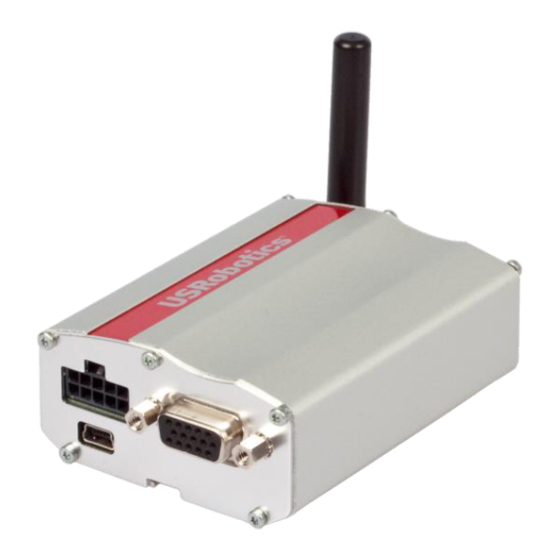
- Page 1 Courier M2M 3G Cellular Modem USR3500 Reference Guide...
-
Page 2: Important Notice
Reference Guide Important Notice Due to the nature of wireless communications, transmission and reception of data can never be guaranteed. Data may be delayed, corrupted (i.e., have errors) or be totally lost. Although significant delays or losses of data are rare when wireless devices are used in a normal manner with a well-constructed network, the modem should not be used in situations where failure to transmit or receive data could result in damage of any kind to the user or any other party, including but not limited to... - Page 3 Reference Guide SIERRA WIRELESS AND/OR USROBOTICS AND/OR THEIR RESPECTIVE AFFILIATES HAVE BEEN ADVISED OF THE POSSIBILITY OF SUCH DAMAGES OR THEY ARE FORESEEABLE OR FOR CLAIMS BY ANY THIRD PARTY. Notwithstanding the foregoing, in no event shall Sierra Wireless or USRobotics and/or their respective affiliates aggregate liability arising under or in connection with the Sierra Wireless/ USRobotic product, regardless of the number of events, occurrences, or claims giving rise to liability, be in excess of the price paid by the...
-
Page 4: Contact Information
Reference Guide SPECIFIC DISCLAIMERS OF LIABILITY: CUSTOMER RECOGNIZES AND ACKNOWLEDGES SIERRA WIRELESS IS NOT RESPONSIBLE FOR AND SHALL NOT BE HELD LIABLE FOR ANY DEFECT OR DEFICIENCY OF ANY KIND OF CELLULAR OR GPS (INCLUDING A-GPS) SERVICES. Patents This product may contain technology developed by or for Sierra Wireless, Inc. ®... -
Page 5: Document History
Reference Guide Document History Version Date Updates Initial release Rev 1.0 1/27/14... -
Page 6: Table Of Contents
Contents CONTENTS ........................ 6 LIST OF FIGURES ..................... 8 LIST OF TABLES ....................... 9 1. FUNCTIONAL SPECIFICATIONS ..............11 1.1. Functional Architecture ................11 1.2. RF Functionalities ..................12 1.3. Operating System .................. - Page 7 Reference Guide 7. RECOMMENDATIONS WHEN USING THE USR3500 ON TRUCKS ....48 7.1. Recommended Power Supply Connection on Trucks ....... 48 7.2. Technical Constraints on Trucks ............... 49 8. RELIABILITY COMPLIANCE AND RECOMMENDED STANDARDS ....
-
Page 8: List Of Figures
USR3500 Back Interface ................. 30 Figure 22. Main RF Connector.................. 31 Figure 23. Secondary RF Connector for USR3500 ..........32 Figure 24. GPS RF Connector for USR3500 ............32 Figure 25. Reset Sequence Diagram ............... -
Page 9: List Of Tables
Microphone Pin Description for USR3500 ..........26 Table 10. Equivalent Circuits of CMIC ..............26 Table 11. Electrical Characteristics of CMIC for USR3500 ........26 Table 12. Recommended Microphone Characteristics ..........27 Table 13. ... - Page 10 33. USR3500 Operating Modes Feature Availability ........43 Table 34. Power Consumption of USR3500 in Connected Mode with Serial Port OFF, Flash LED OFF and USB ON (typical values) ..........44 Table 35. Power Consumption of USR3500 in Non-Connected Mode with UART ON, FLASH LED OFF and USB OFF (typical values) ..........
-
Page 11: Functional Specifications
1. Functional Specifications This section discusses the functional specifications of the USR3500. 1.1. Functional Architecture The global architecture of the USR3500 is shown in the figure below. Figure 1. Functional Architecture Rev 1.0 1/27/14... -
Page 12: Rf Functionalities
Reference Guide Functional Specifications 1.2. RF Functionalities Figure 2. RF Architecture 1.3. Operating System The modem is Open AT Application Framework compliant. With the Courier M2M Open AT application loaded, the modem becomes a solution for many specific market needs. The operating system of the modem is responsible for the following functions: •... -
Page 13: Technical Specifications
2. Technical Specifications 2.1. Power Supply The modem is supplied by an external DC voltage, DC-IN, with a voltage range of +4.75V to +32V. The main regulation is made with an internal DC/DC converter in order to supply all the internal functions with a DC voltage. The correct operation of the modem in Communication mode is not guaranteed if the input voltage falls below 4.75V. -
Page 14: Mechanical Specifications
Reference Guide Technical Specifications 2.2. Mechanical Specifications Figure 3. USR3500 Mechanical Drawing Rev 1.0 1/27/14... -
Page 15: Interfaces
3. Interfaces This section describes the different interfaces that connect with the USR3500. The modem comes with the following interfaces: • 10-pin Micro-Fit Connector • USB Interface (mini-B connector) • 15-pin Sub-D Serial Interface • Main RF Interface • Secondary RF Interface •... - Page 16 Reference Guide Interfaces Figure 5. Power Supply Connector Refer to the following table for the pin description of the power supply connector. Table 2. Power Supply Connector Pin Description Pin # Signal Description GPIO25/INT1 General purpose input/output or Interrupt GPIO35 General purpose input/output Vref Voltage reference for the GPIOs...
- Page 17 Reference Guide Interfaces Refer to the following table for the pin description of the GPIOs. Table 3. GPIO Pin Description Pin # Signal I/O Voltage Description GPIO25/INT 1 Vref General purpose input/output or Interrupt GPIO35 Vref General purpose input/output Vref 2.8V ~ 15V Voltage reference for the GPIOs Note:...
- Page 18 Reference Guide Interfaces Figure 7. Equivalent Circuit of V , Vref = 2.8V Figure 8. Equivalent Circuit of V , Vref = 2.8V Figure 9. Equivalent Circuit of V , Vref = 2.8V With Vref > 2.8V, both GPIO35 and GPIO25 may be interfaced with a component that complies with the following levels.
- Page 19 Reference Guide Interfaces Value without external load. Figure 10. Equivalent Circuit of V , Vref > 2.8V Figure 11. Equivalent circuit of V , Vref > 2.8V Figure 12. Equivalent circuit of V , Vref > 2.8V Figure 13. Equivalent circuit of V , Vref >...
- Page 20 Reference Guide Interfaces • Act as a status reading when the GPIO is configured as input. The GPIOs may be controlled with the following AT commands: • AT+WIOW for write access to the GPIO value, when the GPIO is used as an output •...
-
Page 21: Serial Interface
Reference Guide Interfaces 3.1.1.2. ON/OFF Pin The modem has an external ON/OFF pin which is used to turn the device ON or OFF. The following table describes the operation of this pin. Table 6. ON/OFF Pin Operation Condition State Power Supply Operation When 4.75V to 32V supply is Open... - Page 22 Reference Guide Interfaces Refer to the following table for the pin description of the 15-pin serial connector. Table 8. Serial Connector Pin Description Pin # Signal I/O Type Reset State Description CT109/DCD +/- 5.5V Undefined Data Carrier Detect CT103/TXD +/- 5.5V Transmit Serial Data Reserved Do not connect...
- Page 23 CT105/RTS and CT106/CTS for hardware flow control in order to avoid data corruption during transmission. The USR3500 also implements the Serial Port Auto Shut Down feature with the DTR signal. It is recommended to use the CT108-2/DTR signal to benefit from the current consumption improvement performed by this feature.
- Page 24 Reference Guide Interfaces Figure 16. V24 Serial Link Implementation for a 5-wire UART 3.1.2.2.2. 4-wire Serial Interface RS232 Implementation The signals used in this interface are as follows: • CT103/TXD • CT104/RXD • CT105/RTS • CT106/CTS Figure 17. V24 Serial Link Implementation for a 4-wire UART 3.1.2.2.3.
-
Page 25: Autobauding Mode
Reference Guide Interfaces Figure 18. V24 Serial Link Implementation for a 2-wire UART The CT105/RTS and the CT106/CTS signals are not used in this configuration. Configure the AT command AT+IFC=0,0 to disable the flow control function. Refer to the AT Commands Interface Guide at http://www.usr.com/support/3500 for more information regarding AT Commands. - Page 26 Microphone positive input CMIC1N Analog Microphone negative input Table 10. Equivalent Circuits of CMIC DC Equivalent Circuit AC Equivalent Circuit Table 11. Electrical Characteristics of CMIC for USR3500 Parameters Unit DC Characteristics AC Characteristics 200 Hz<F<4 kΩ AT+VGT*=3500dB 13.8 Working voltage AT+VGT*=2000dB 77.5...
- Page 27 AT+WDGR. Refer to the AT Commands Interface Guide at http://www.usr.com/support/3500 for more information about these AT commands. The following table shows the pin assignments of the speaker output. Table 13. Speaker Outputs Pin Description for USR3500 (Sub D 15-pin) Signal I/O Type Description Pin #...
- Page 28 Reference Guide Interfaces Figure 19. Equivalent Circuit of CSPK Table 14. Electrical Characteristics of CSPK for USR3500 Parameters Unit Biasing voltage CSPKxP and CSPKxN -1.5 RL=16Ω: AT+VGR=-1600*; single-ended Output swing voltage RL=32Ω: AT+VGR=-1600*; single-ended 2.75 Load resistance 14.5 Ω Output current; peak value; RL=16Ω...
-
Page 29: Usb Interface
Differential data interface negative Differential data interface positive Not connected Ground The USR3500 USB slave interface complies with USB 2.0 protocol signaling and with USB 2.0 electrical interface. The USB interface features: • 480Mbit/s high-speed transfer rate • 3.3V type compatible •... -
Page 30: Back Interface
USR3500 Back Interface 3.2.1. SIM Interface A SIM card can be directly connected to the USR3500 through the embedded SIM socket. This interface controls 3V / 1V8 SIM cards and it is fully compliant with GSM 11.11 recommendations concerning SIM functions. -
Page 31: Sim Socket Pin Description
SIM-IO pull up is about 10KΩ. SIMPRES pull low is about 100KΩ. 3.2.2. RF Interface The USR3500 has three RF interfaces. Refer to the following table for the list of available RF interfaces. Table 19. Available RF Interfaces Secondary RF... - Page 32 Reference Guide Interfaces Figure 23. Secondary RF Connector for USR3500 The GPS RF interface is used for GPS antenna connection. It is an MMCX type connector and its nominal impedance is 50Ω. It also provides bias for active antenna. For more details, refer to section 3.2.2.3.6 Active GPS Antenna Bias.
-
Page 33: Antenna Specifications
Antennas used with the USR3500 must have a maximum antenna gain of 1 dBi for Bands 900 and 1800, and 2.5 dBi for Band 2100. Table 22. - Page 34 Reference Guide Interfaces The USR3500 GPS antenna must meet the requirements specified in the table below. Table 23. GPS Antenna Specifications for USR3500 Characteristic GPS L1 RX Frequency 1575.42 MHz RF Impedance 50Ω VSWR Rx max 1.5:1 LNA Bias Voltage...
- Page 35 Reference Guide Interfaces • Best if downloaded once every 1–2 days, but valid for up to 7 days with some accuracy degradation Rev 1.0 1/27/14...
- Page 36 Supported sentences: GGA, GSA, GSV, RMC, VTG 3.2.2.3.6. Active GPS Antenna Bias The USR3500 provides bias for active antenna, which can be enabled or disabled using GPIO44. Note that GPIO44 needs to be at high level for antenna bias to be activated.
-
Page 37: Signals And Indicators
The USR3500 will remain in Low Power mode until the alarm is triggered to start the USR3500 up. Note: Refer to section 3.1.1.2 ON/OFF Pin for more information on how to turn the USR3500 ON or OFF using the ON/OFF pin. Table 24. - Page 38 USR3500 Reset Status (Serial Signal I/O Type Voltage Description Port) Pin # Reset Open drain USR3500 Reset Table 26. Reset Electrical Characteristics for USR3500 Parameter Minimum Typical Maximum Unit Input Impedance (R)* kΩ Input Impedance (C) Internal pull-up Table 27.
-
Page 39: Reset Sequence
USR3500. Refer to the AT Commands Interface Guide at http://www.usr.com/support/3500 for more information regarding AT commands. 4.3. LED Status Indicator The USR3500 has a red LED that indicates the current operational status of the device. Table 28. USR3500 LED Status USR3500 State... -
Page 40: Real Time Clock (Rtc)
LED using an AT command. 4.4. Real Time Clock (RTC) The USR3500 has implemented Real Time Clock for saving date and time when the USR3500 is unplugged from the DC power supply through the DC power cable. Table 29. Real Time Clock Specifications... -
Page 41: Expansion
5. Expansion 5.1. Expansion Compartment The expansion compartment allows users to easily expand the USR3500’s features (Ethernet, for example) for their own applications. Figure 26. USR3500 expansion compartment Refer to the Ethernet Expansion Card User Guide at http://www.usr.com/support/3500 for more information regarding this feature. -
Page 42: Power Consumption
The table below gives the average power consumption of the USR3500 for the first 10s when power supply (DC-IN, supplied by Agilent 66321D in this example) is initially applied to it with no serial port, LED ON or SIM card at ambient temperature. -
Page 43: Working Mode Features
The modem Flash LED can be enabled or disabled by AT command. Refer to Activated/Deactivated section for more information on this feature. 6.2. Working Mode Features The table below sums up the feature availability in each mode. Table 33. USR3500 Operating Modes Feature Availability ACTIVE SLEEP Mode Mode Alarm ACTIVE... -
Page 44: Connected Mode Power Consumption
Reference Guide Power Consumption 6.3. Connected Mode Power Consumption Table 34. Power Consumption of USR3500 in Connected Mode with Serial Port OFF, Flash LED OFF and USB ON (typical values) average peak Mode Parameters Unit DC-IN DC-IN DC-IN DC-IN DC-IN =4.75V... - Page 45 Reference Guide Power Consumption average peak Mode Parameters Unit DC-IN DC-IN DC-IN DC-IN DC-IN =4.75V =13.2V =32V =4.75V =13.2V +22 dBm 1090 Band I +10 dBm 1057 +22 dBm 1074 Band II +10 dBm 1062 +22 dBm 1042 UMTS Band V (Voice) +10 dBm +22 dBm...
-
Page 46: Non-Connected Mode Power Consumption
Reference Guide Power Consumption 6.4. Non-Connected Mode Power Consumption Note: The USB port must be deactivated to enter Sleep Mode. Rev 1.0 1/27/14... - Page 47 Reference Guide Power Consumption Table 35. Power Consumption of USR3500 in Non-Connected Mode with UART ON, FLASH LED OFF and USB OFF (typical values) average Serial Port Mode Unit Status DC-IN=4.75V DC-IN=13.2V DC-IN=32V 45.82 16.56 Active Idle Mode, HSPA 15.48 5.96...
-
Page 48: Recommendations When Using The Usr3500 On Trucks
7. Recommendations when Using the USR3500 on Trucks Caution: The power supply connection of the modem must never be directly connected to the truck battery. 7.1. Recommended Power Supply Connection on Trucks All trucks have a circuit breaker on the exterior of the cabin. The circuit breaker is used for safety reasons: if a fire blazes in the trucks, (for example, on the wiring trunk) the driver may cut the current source to avoid any damage (explosion). -
Page 49: Technical Constraints On Trucks
Recommendations when Using Reference Guide the USR3500 on Trucks 7.2. Technical Constraints on Trucks It is highly recommended to directly connect the power supply on the circuit breaker rather than on the battery. The modem may be damaged when starting the truck if the circuit breaker is switched OFF (in this case, the truck ground and the battery ground will be connected through the modem as shown in the following figure). -
Page 50: Reliability Compliance And Recommended Standards
International Electro technical Commission International Organization for Standardization 8.2. Applicable Standards Listing The table hereafter gives the basic list of standards applicable to the USR3500. Note: References to any features can be found from these standards. Table 37. Applicable Standards and Requirements for the modem... -
Page 51: Environmental Specifications
IEC60068252 2.0 w/COR solution). 8.3. Environmental Specifications The USR3500 is compliant with the operating classes listed below. The ideal temperature range of the environment for each operating class is also specified. Table 38. Operating Class Temperature Range Conditions Temperature Range Operating / Class A -20 °C to +55°C... -
Page 52: Function Status Classification
Reliability Compliance and Reference Guide Recommended Standards 8.3.1. Function Status Classification The classes reported below comply with the Annex “ISO Failure Mode Severity Classification”, ISO Standard 7637, and Section 1. Note: The word “function” used here only concerns the function performed by the modem. Table 39. -
Page 53: Certification Compliance And Recommended Standards
9. Certification Compliance and Recommended Standards 9.1. Certification Compliance Refer to the following tables for the requirements compliance of the USR3500. Table 40. Standards Conformity for USR3500 Domain Applicable Standard IEC 60950:2005+A1:2009 Safety & Health EN 60950:2006+A11:2009+A1:2010+A12:2011 EN 62311: 2008 EN 301 440-1, v1.6.1... -
Page 54: Applicable Standards Listing
Applicable Standards Listing The table hereafter gives the basic list of standards applicable for 2G and 3G (HSPA). Note: References to any features can be found from these standards. Table 41. Applicable Standards and Requirements for USR3500 Current Document Title Version GCF-CC 3.46.0... -
Page 55: Safety Recommendations
10. Safety Recommendations 10.1. General Safety For the efficient and safe operation of your programmable modem, please read the following information carefully. It is important to follow any special regulations regarding the use of radio equipment due in particular to the possibility of radio frequency (RF) interference. Carefully follow the safety advice given. - Page 56 Reference Guide Safety Recommendations There may be a hazard associated with the operation of your USR3500 close to inadequately protected personal medical devices such as hearing aids and pacemakers. Consult the manufacturers of the medical device to determine if it is adequately protected.
-
Page 57: Rf Safety
Respect national regulations on the use of cellular telephones in vehicles. Road safety always comes first. If incorrectly installed in a vehicle, the operation of the USR3500 could interfere with the correct functioning of vehicle electronics. To avoid such problems, make sure Rev 1.0... -
Page 58: Care And Maintenance
Do not expose the USR3500 to any extreme environment where the temperature or humidity is high. Do not use or store the USR3500 in dusty or dirty areas. Its moving parts can be damaged. Do not attempt to disassemble the modem. There are no user serviceable parts inside. -
Page 59: Reference Documents
11. Reference Documents For more details, several reference documents can be consulted. The documents referenced herein are provided by USRobotics. Visit the USRobotics website at for the latest documentation available. http://www.usr.com/ 11.1. Firmware Documentation AT Commands Interface Guide Customer Release Notes for Firmware 7.52 A1 11.2. -
Page 60: List Of Abbreviations
12. List of Abbreviations Abbreviation Definition Alternating Current Accumulated Call Meter Adaptive Multi-Rate ® ATtention (prefix for Wireless CPU commands) CLocK CMOS Complementary Metal Oxide Semiconductor Coding Scheme Clear To Send Decibel Decibel relative to the Carrier power Decibel relative to an Isotropic radiator Decibel relative to one milliwatt Direct Current Data Carrier Detect... - Page 61 Reference Guide List of Abbreviations Abbreviation Definition International Electrotechnical Commission Internal Expansion Socket IESM Internal Expansion Socket Module IMEI International Mobile Equipment Identification Input / Output Light Emitting Diode MAXimum Mobile Equipment MICrophone Micro-Fit Family of connectors from Molex MINimum Microcom Networking Protocol Mobile Originated Mobile Station...
- Page 62 Reference Guide List of Abbreviations Abbreviation Definition TYPical UMTS Universal Mobile Telecommunications System VSWR Voltage Standing Wave Ratio Rev 1.0 1/27/14...
- Page 63 Rev 1.0 1/27/14...